Close
0%
0%

LED Microscope Illuminator

An LED illuminator for an assembly microscope.

Similar projects worth following
520 views
I have been wanting to play with LEDs for illumination for a while. A need for low cost microscope illuminators came up, so this seems like a good opportunity. This is as much a mechanical project as an electronic one. High current LEDs need serious heat sinking to operate continuously, so I designed a heat sink/mounting head that will screw onto a microphone gooseneck for a convenient mounting system that the users will already be familiar with. The electronics will be powered by a 2 amp 18V wall wart.

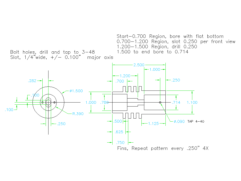
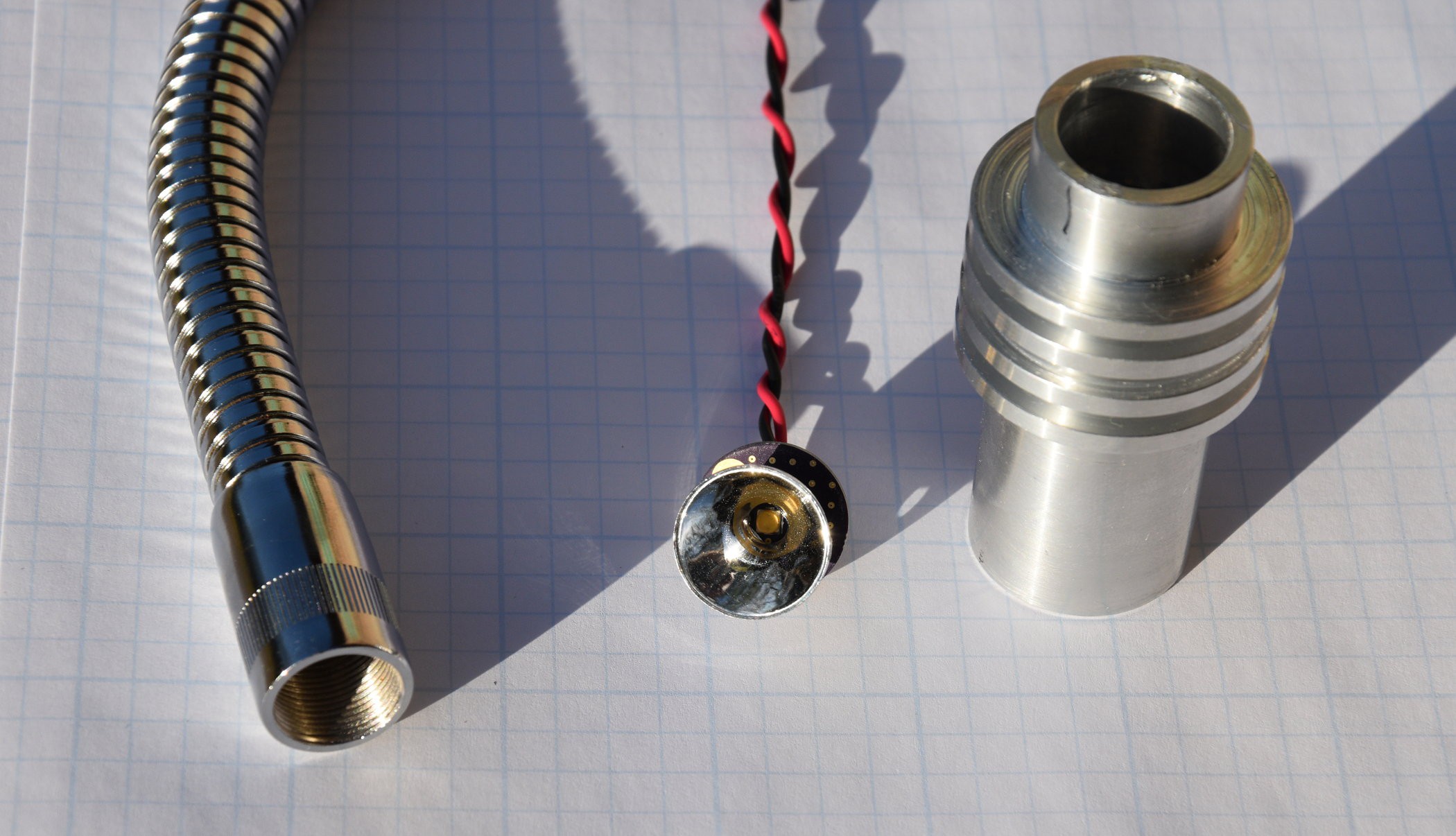
This project is using a couple of the OSRAM Oslon warm white 3000K LEDs. Initial experiments with these LEDs indicates that they will provide more than adequate light for an assembly microscope. I built up a board to go behind a 50 mm reflector, but that reflector seemed more like it was designed for a flash light. The second rev board was designed around the reflector shown in the picture. This has a good tight beam and uniform distribution.  A heat sink was designed to be machined out of 1.5" aluminum bar stock that would mount on the end of a 20" microphone gooseneck to allow the user to direct the lights where they want them.
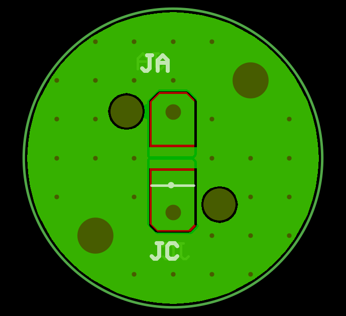
The LED mounting board has lots of copper on both sides, and is stitched with vias to get the heat off the front side (LED side) and into the heat sink that will be bolted to the back side of the board. The LED is rated at up to 1.8A continuous, but initial tests look like 300mA will be sufficient.
I spent an entertaining day simulating a design for a hysteretic constant current power supply, but when the design was complete, the parts cost was going to be about $15. Digging around on Digi-key, they had 2A LED driver chips for $0.65. I laid out a 2 layer PCB for the driver chip.

Illuminator_Power_Supply.pdf

Schematic for Illumintor Power Supply

Adobe Portable Document Format - 98.81 kB - 04/19/2018 at 02:19

Preview

  • 2 × LEDs OSRAM Oslon GW CSSRM2.CM M3M5-xx57-1 3000K white LED
  • 2 × Reflectors Regina C11347 19mm round Spot Reflector
  • 1 × LED Driver chip Diodes Inc AL8861Y-13 LED Driver Chip
  • 1 × Current sense Resistor 0.1 Ohm 1 Watt 1%
  • 1 × Inductor 100uH, 1.96A fixed Inductor

View all 9 components

  • Illuminator is complete

    Bharbour05/28/2018 at 15:47 0 comments

    After solving the electronic problems, my illuminator needed an enclosure.

    Finished Illmuminator in Enclosure

    A powder coated aluminum box, with a counterweight to keep it from being nose heavy when the LEDs are extended. The counterweight is a solid slab of aluminum.

    The box was simple to powdercoat, it is .050" 5052 aluminum with powder on one side only. In about 7 minutes, the box had come up to the powder flow out temperature which is about 330F for this powder. The counterweight was a little more work. It is .875" solid aluminum, and it is coated on all sides. I am using an old electric kitchen oven for my powdercoating work, so the volume is sort of limited. I masked the sides of the block and coated the bottom surface. After placing it in the oven, it took 45 minutes to come up to the flow out temperature of the powder. Ten minutes later, I removed it from the oven and let it cool. It took another 30 minutes to cool enough that I could touch it to remove the masking. I threaded long screws into the tapped holes on the bottom surface to let the block sit on the screw heads rather than the already coated, bottom surface.  I set the block on a sheet of aluminum to handle, and coated it. As the block was still at about 130F, it only took about 30 minutes to come up to the flow out temperature.

    The counterweight was the largest piece that I have powdercoated to date. Generally, I send large pieces out.

    Powdercoating is a really good way to finish metal parts. It is a lot tougher finish than rattle can spray paint. It flows well and fills imperfections in the metal finish pretty well. Cleaning up the powder coat gun is a lot easier than cleaning up a traditional spray gun. Inexpensive powdercoat guns can be bought from a number of places on the web. The oven is probably the biggest hassle on it. We replaced our old kitchen oven a few years ago, and I kept the old one for powdercoating. Don't even consider using an oven used for  food preparation oven for powdercoating! Your spouse will kill you if the powder does not.

  • Progress on the Power Supply

    Bharbour05/13/2018 at 21:23 0 comments

    The new revision PCBs and new inductors came in late last week.

    For comparison sake, I replaced the 100uH inductor with a 33uH inductor on the rev 1 PCB. The AL8861 data sheet lists 100uH as a legal inductor value, and I wanted to keep the operating frequency as low as possible, to keep spurious RF emissions down, so I started the project using the 100uH inductors. The example schematic diagram in the data sheet and both revisions of their eval boards used 33uH inductors. Anyway, the rev 1 PCB with the 33uH inductors worked better. There was less noise on the switch node waveform, and the current controlled better. There was still enough noise on the switch node to cause problems at high current though.

    The rev 2 PCB has several improvements over the rev 1 board:

       4x the capacitance on the input power supply.

       Got rid of the Schottky diode in series with the input power.

       Lots more copper on the power distribution network.

       Lots more copper on the switch node (U1 to inductor L1) connection.

       Footprints for capacitors across the LEDs and the current sense Resistor.

       Tighter layout of the current feedback net.

    After building up the the rev 2 board with the 33uH inductor, it works much better. The input current shows almost no AC on it at all - the additional input caps solved that issue. The noise on the switch node with 1 or 2 LEDs is gone, it is a variable duty cycle square wave. The current to the LEDs, even with the long wiring in the goosenecks is very clean. Curiously, it looks more sinusoidal than triangular. This may be a consequence of the capacitor that I put across the LED connections on the new PCB forming a resonant circuit.

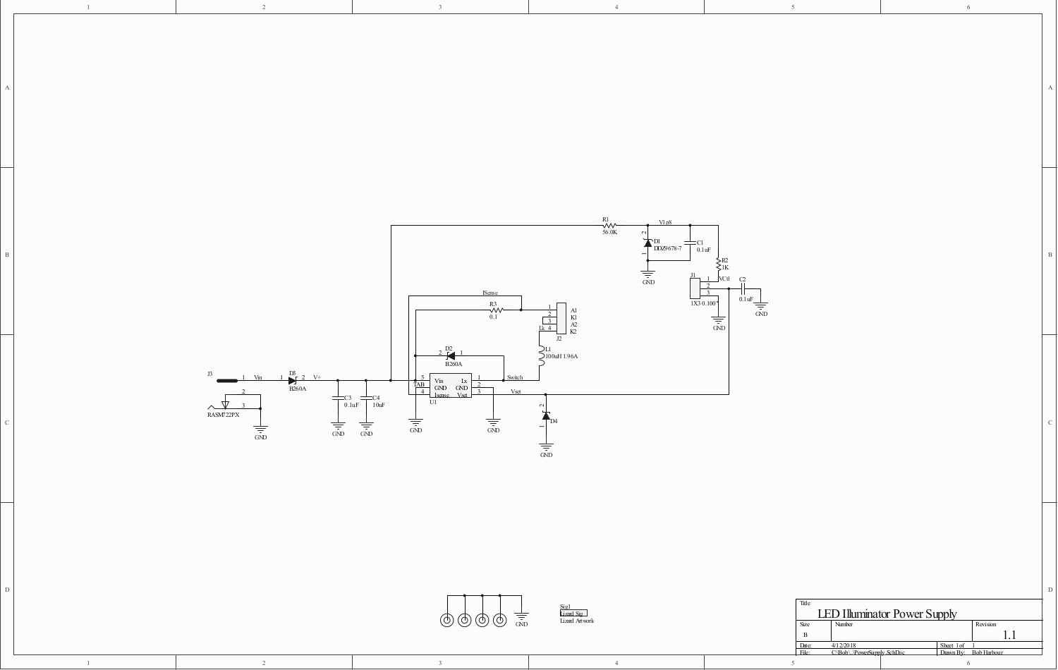
    For comparison, here is the old schematic:

    Rev 1 Schematic Diagram

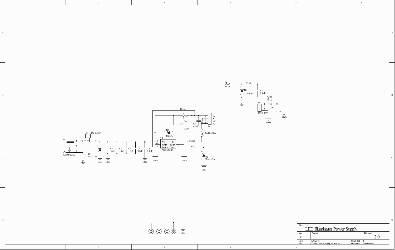
    Next, the new schematic with the additional input capacitance and the caps across the LED connector and the current sense resistor. The cap across the current sense resistor was not placed when the board was built and does not appear to be needed.

    Rev 2 Schematic Diagram

    The inductor L1 on the second rev board was populated with a 33uH part instead of the 100uH part. Also, resistor R3 was populated with 4.4K rather than 1.0K to reduce the maximum current setpoint.

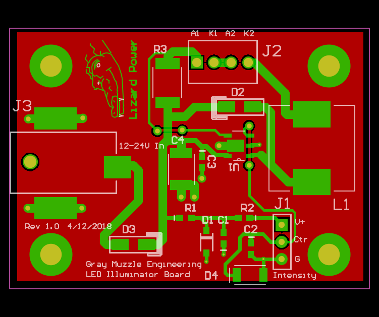
    Here is the rev 1 PCB layout. The power distribution between the input connector J3 and D3 anode is only 0.050" wide copper on the top (green) side of the board. Similarly, from D3 cathode to R3, D2 cathode, C4 and U1 pin 5 are 0.050" wide or less. The current sense trace is the skinny trace between R3 and the Lizard can be seen looping around a fair area. 


    Rev 1 PCB Layout

    Below, the Rev 2 PCB layout can be seen.

    N PCB rev 2 Layout

    The 0.050" power distribution was replaced with polygons, offering lower impedance between the 4 input filter capacitors and the rest of the circuit. The current sense trace runs mostly on the bottom side of the board (red) and has less loop area, providing less opportunity for noise. Both the U1 to L1 connection and the L1 to LED connector are heavy polygons for lower impedance.

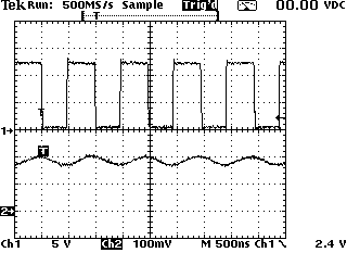
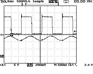
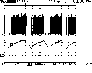
    Between the new PCB layout and the lower inductor value, the performance of this power supply is acceptable now. Scope shots of the switch node voltage (ch1) and the inductor current (ch2) look pretty reasonable. The scope shot below is running at about 135mA of LED current. The previous board would operate at this level.

    Scope Shot of Switch Node Voltage (Ch1) and Inductor Current (ch2) at 135mA LED Current.

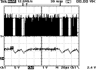
    The next scope shot shows the power supply running at about 375mA of LED current.

    Scope Shot of Switch Node Voltage (ch1) and Inductor Current (ch2) at 375mA LED current.

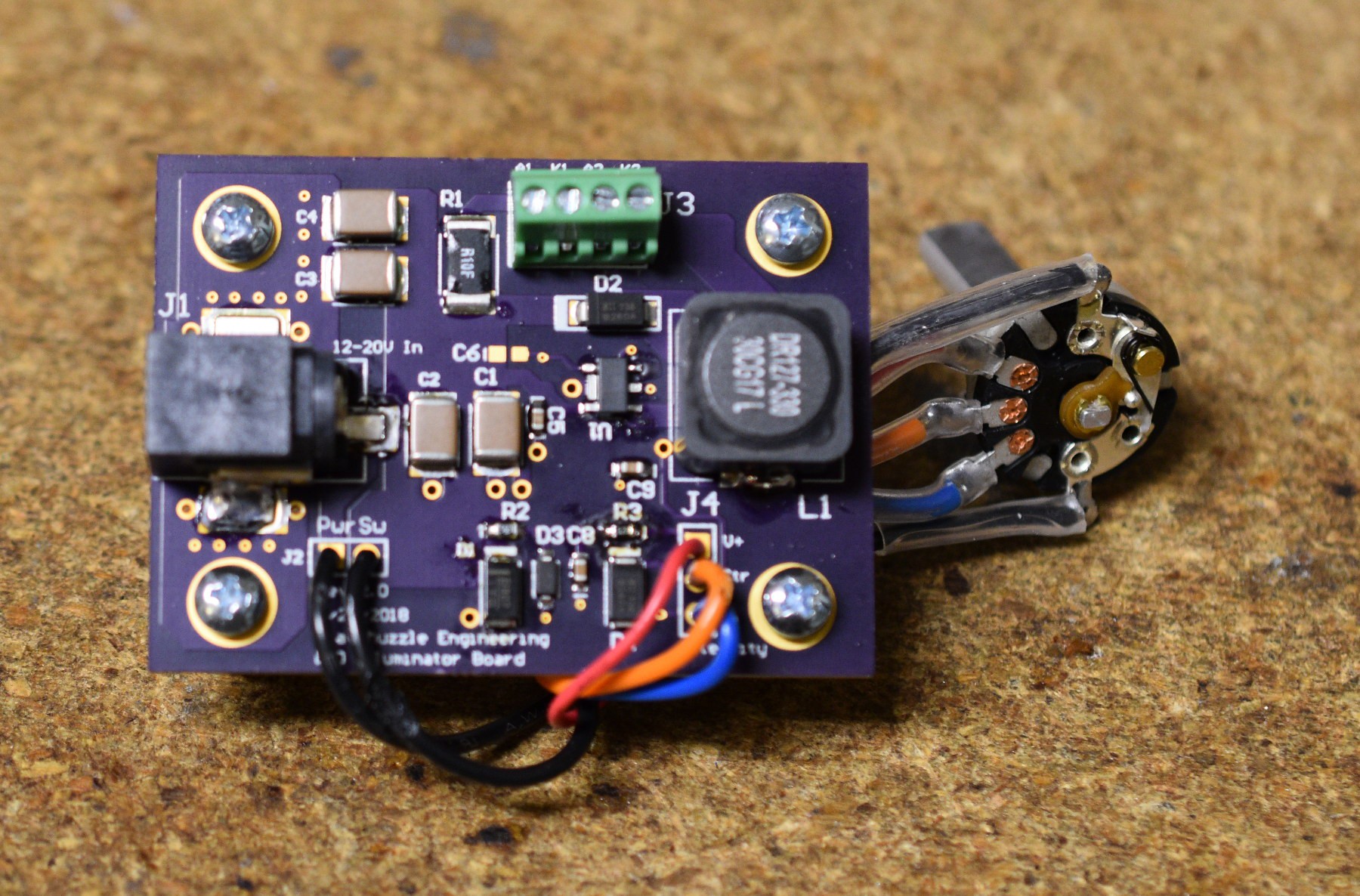
    With this much LED current, the previous board would be showing an unacceptable amount of noise and getting hotter than I like. There is still a small amount of ringing on the switch node voltage when the switch turns off and the current begins flowing through D2, but this is not unusual in circuits of this type, and I am going to live with it. The new board runs cool, barely above ambient temperature. Sadly there was not enough room on the top side of the board for the Lizard...

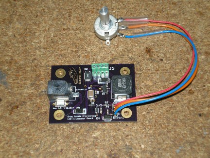
    Assembled, rev 2 LED Power Supply PCB with Brightness/Power Switch
    Assembled, rev 2 LED...
    Read more »

  • Scope Shots of Noise Problem

    Bharbour05/06/2018 at 20:52 0 comments

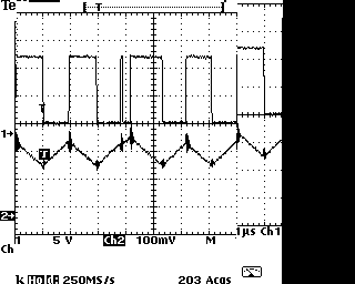
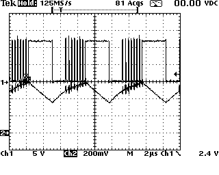
    Here is a series of scope shots at different LED current Settings. All tests were done with 2 LEDs in series, 12V input supply to board. All of the scope shots show channel 1 as the voltage on the switch node and channel 2 as LED current. Wiring on the two LEDs was very short, around 3" each.

    This scope shot shows board operating at a fairly low current setting. The LED current is oscillating around the setpoint cleanly and the switch node is mostly clean. Note the one noise spike on the switch node, just to the left of center. This spike occurs when the switch is turned on.

    This scope shot shows the board operating at a higher LED current. Note the noise spikes on the switch node are more frequent and are corrupting the LED current somewhat.

    This scope shot shows the board operating at a higher current setting. The noise on the switching node is very severe. You can see that it is changing the pulse widths on the switch node and the current waveform.

    This is operating at the highest setting that my design is configured for. The noise has become so severe that the periodic switching has almost disappeared.

    Testing with a single LED gives very similar results, but at different current settings.

    I tried testing into a short circuit which is not a big problem because this is s current regulator. Even into a short circuit, the noise on the switch node appears.

    At this point, I am waiting for the next rev PCB to come back from OSHPark. The next board rev has a lot more copper on the power, switch nodes and ground, as well as more capacitance on the power input. My expectations of success with this are not very high.

  • Trouble with Current Control

    Bharbour04/29/2018 at 16:00 0 comments

    The LED driver chip (AL8861) is specified to drive up to 1.5 amps across the LEDs. I only want to be able to drive 750mA accross the LEDs. I am using two Osram LEDs spec'd at up to 1.8A, connected in series. The input voltage to the control board is either 12V or 18V, well within the spec of the driver chip.

    Examining the output current from the Illuminator Power supply, the output current is not controlling properly. The LED driver chip (AL8861) looks a lot like a buck converter power supply, except this one ignores the output voltage and monitors the current only. Looking at the schematic, a 0.1 Ohm current sense resistor (R3) goes from Vin to the Anode of the LEDs (via J2). Current returning from the cathode of the LED (J2 pin 4) goes into the inductor (L1). The lower end of the inductor goes to the switch pin on the chip (U1) and the anode of a schottky diode (D2). The current through R1, LEDs, L1 is measured by the voltage drop across R3. The current setpoint (brightness) is set via a DC voltage from a potentiometer connected to J1. Zener diode D1, R1 form a crude voltage regulator (about 1.6V) for the control setpoint.

    When the chip powers up, the  LED/Inductor current is below the turn off threshold, so the switch pin on the chip grounds the lower end of the inductor, and the current rises fairly linearly with time. When the LED/Inductor current rises to the turn off threshold, the switch pin on the chip turns off. The inductive kickback drives the lower end of the inductor to a positive voltage. When that voltage rises above the Vin, D2 starts conducting and the LED/Inductor current circulates through the LEDs, L1 and D2. There is hysteresis in the comparator monitoring the voltage from the sense resistor, so the LED/Inductor current must decay to a slightly lower point than the turn off point before it turns the switch in the chip back on to start replacing the energy in the inductor that was consumed while the switch was off. The system normally runs in this region, with the LED/Inductor current oscillating between the turn off point and the turn on point. The frequency is set by the Inductor value, the LED power and the input voltage. It is designed to run around 300KHz, but the chip is spec'd to operate up to 1MHz.

    Adjusting the voltage to the brightness control pin moves the turn off/turn on points, and sets the average current through the LEDs.

    The design that I used for the PC board was based on the Data Sheet "Typical Application" drawing.

    The problem that I am seeing is that as the current in the LEDs is increased, high speed noise is appearing on the switch pin of the chip causing the current to be measured incorrectly. When the chip is operating normally the current oscillates in a roughly triangular waveform riding on a DC level and the voltage on the switch pin is a clean square wave. When the noise starts showing up, the oscillations get much larger and less regular. The voltage on the switch pin has fast spikes while the switch is on, indicating that the switch is turning off briefly.

    The first thing that i tried was to put more capacitance on the power input. A 470uF cap at the power input connector was used. This changed nothing.

    Next, I put a 100pF cap in parallel with the current sense resistor (R3). This improved the behavior some, increasing the current where the noise started showing up, but it still had problems below the current that I wanted to operate the LEDs at. Some being good, more might be better... so I replaced the 100pf cap with a 0.1uF cap. This changed the behavior. The current could be increased considerably higher than with the 100pF cap, but before it reached the level that I wanted, the triangular oscillation on the current waveform disappeared and the switching frequency of the inductor current went up to about 4MHz from the 300KHz range. In this mode, I have no idea how the chip is operating. The inductor current appears to be constant. It adjusts with...

    Read more »

  • Power Control Board Back from Fab

    Bharbour04/24/2018 at 02:47 0 comments

    The Power Control Board came back from OSHPark today. It looks good, so I built one up to test it.

    The current control is pretty reasonable, and appears to be stable as the LEDs warm up. I need to add a connector to the input power feed for a switch, and I should add a TVS diode on the input power feed just to protect stuff against plugging the wall wart into the board while the wall wart is powered up. The inductance of the cable can create a fair size spike.

    I need to put some more time into checking the board out, as this is the first time that I have used this chip. There are some oddities on the output current waveform that i want to understand before I declare victory on this one.

  • Heat Sink Fabrication

    Bharbour04/19/2018 at 02:36 0 comments

    I spent the day machining some heat sinks. It did not go well, but in the end, I have 3 usable heat sinks. The mounting holes in the LED PCBs are undersized. They were spec'd at 0.93" which should have been a clearance hole for a 3-48 machine screw, but they needed to be spec'd to the next size up. I tried to drill and tap a heat sink for a 2-56 machine screw, but the drill bit snapped in the hole. Thinking I got lucky because there was enough bit sticking out of the hole, I extracted a piece. It turned out the bit snapped in multiple places, and the deeper pieces were un-removable. Considering that there was a couple of hours of work in the part by that time, I rotated the PCB and drilled new holes for the 3-48 screws. All told, the dimensions don't match the drawings, but stuff fits and should work. Now I need to wait for more bare PCBs to come in.


    Assembled the first complete light head and it went together correctly and looks good. Initial tests were done using the 4000K version of the LED and the board that I put together today uses the 3000K version. It looks very much like the light from an incandescent bulb, which is what I want.

View all 6 project logs

Enjoy this project?

Share

Discussions

Similar Projects

Does this project spark your interest?

Become a member to follow this project and never miss any updates