The Menorah555 assembly consists of three main parts: the printed circuit board assembly (PCBA), the LED flame diffusers, and the bent acrylic base. Details (excruciating) on each of those follow.
PCBA
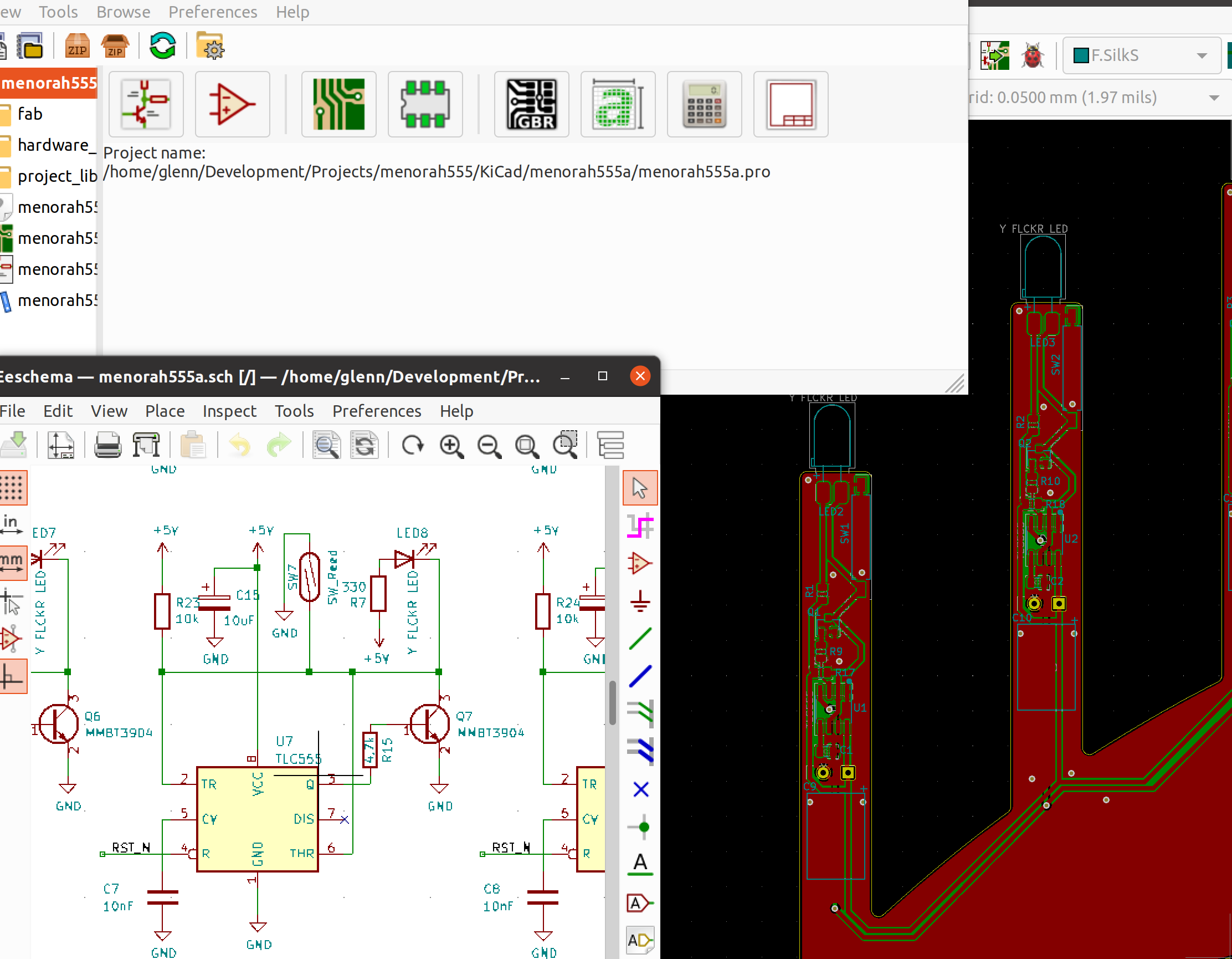
The Menorah555's schematic and PCB were designed in KiCad 5.1.12. There are only a few different parts to the schematic since much of it is repeated for the eight non-shamash candles.

The main parts of the schematic include the shamash, current limiter, candles, and power-on reset.
Shamash
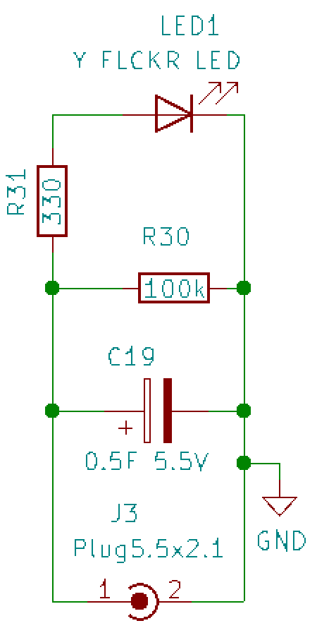
The shamash candle, like all the other candles, is designed with an LED that looks like a standard T-1 3/4 LED with a 5-mm diameter, but it actually has a chip inside that applies PWM to the LED in a way that simulates a flickering candle. Using this type of LED eliminates the need to use a separate microcontroller to create that effect. A 330-ohm resistor is put in series with the LED to limit the current and set the brightness.

Since the shamash is removed and used to "light" the
other candles, it needs a power source to keep it lit during that
time, maybe 30 seconds. That role is filled by a 0.5-F
supercapacitor. That is 0.5 farads, not microfarads,
so it holds a LOT of charge. In fact, this holds way more than
necessary, but I wanted a capacitor that would lay flat to give the
suggestion of a cylindrical candle shape. This supercap charges in a
couple of seconds, but actually keeps the LED lit for 10 minutes
before it gets noticeably dim and is still very dimly lit at 20
minutes, so you can really take your time lighting the other candles!
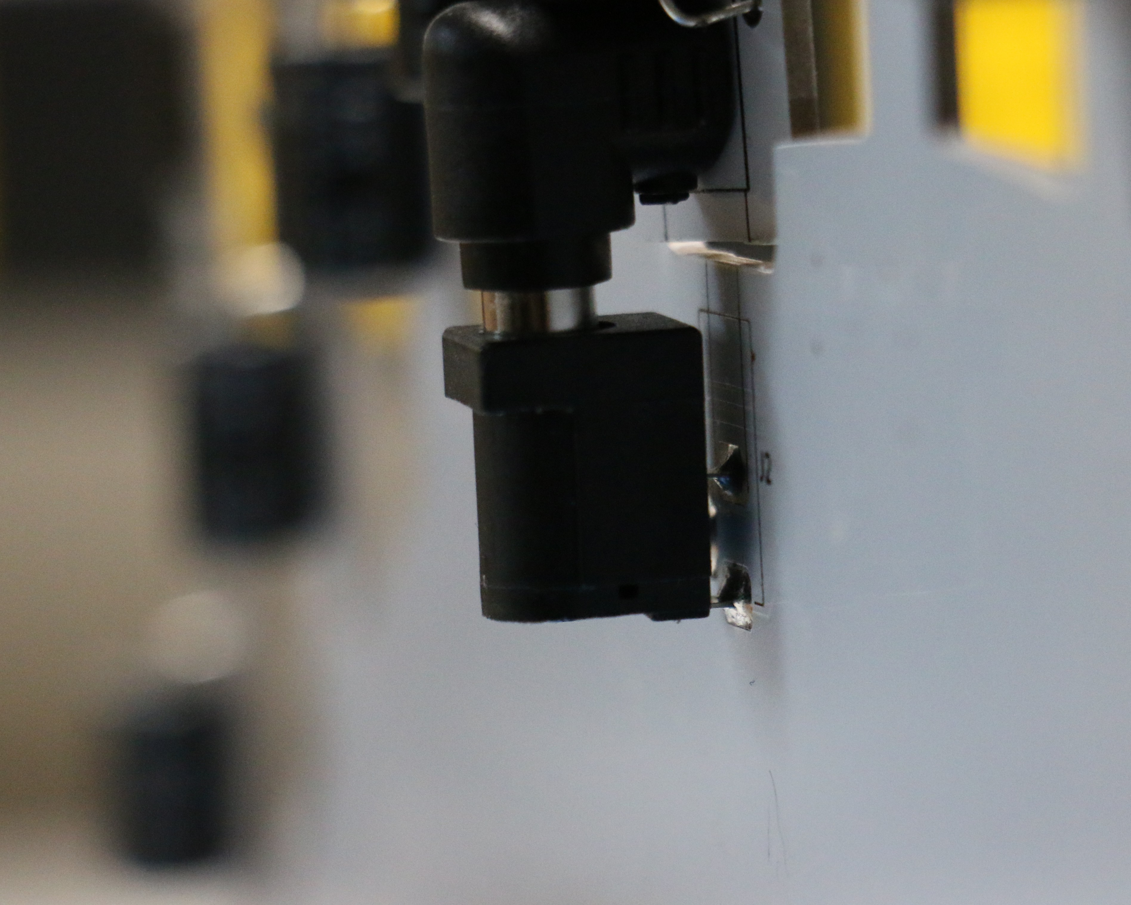
A common barrel-style power connector was used so that the shamash PCBA can be unplugged from the mainboard and used to light the other candles.
Current Limiter
The menorah has a micro-USB connector so that it can be powered with a USB charger or battery pack. These power supplies are designed to supply at least 500mA, although they may supply more. However, the inrush current on the 0.5F supercap may be much more than that and it could send the power supply into an over-current condition. Since this is undesirable, a current limiter circuit was added to prevent this.
This current limiter is not very precise, but there is no need for great precision because we don't need an exact current, as long as it's less than 500mA.

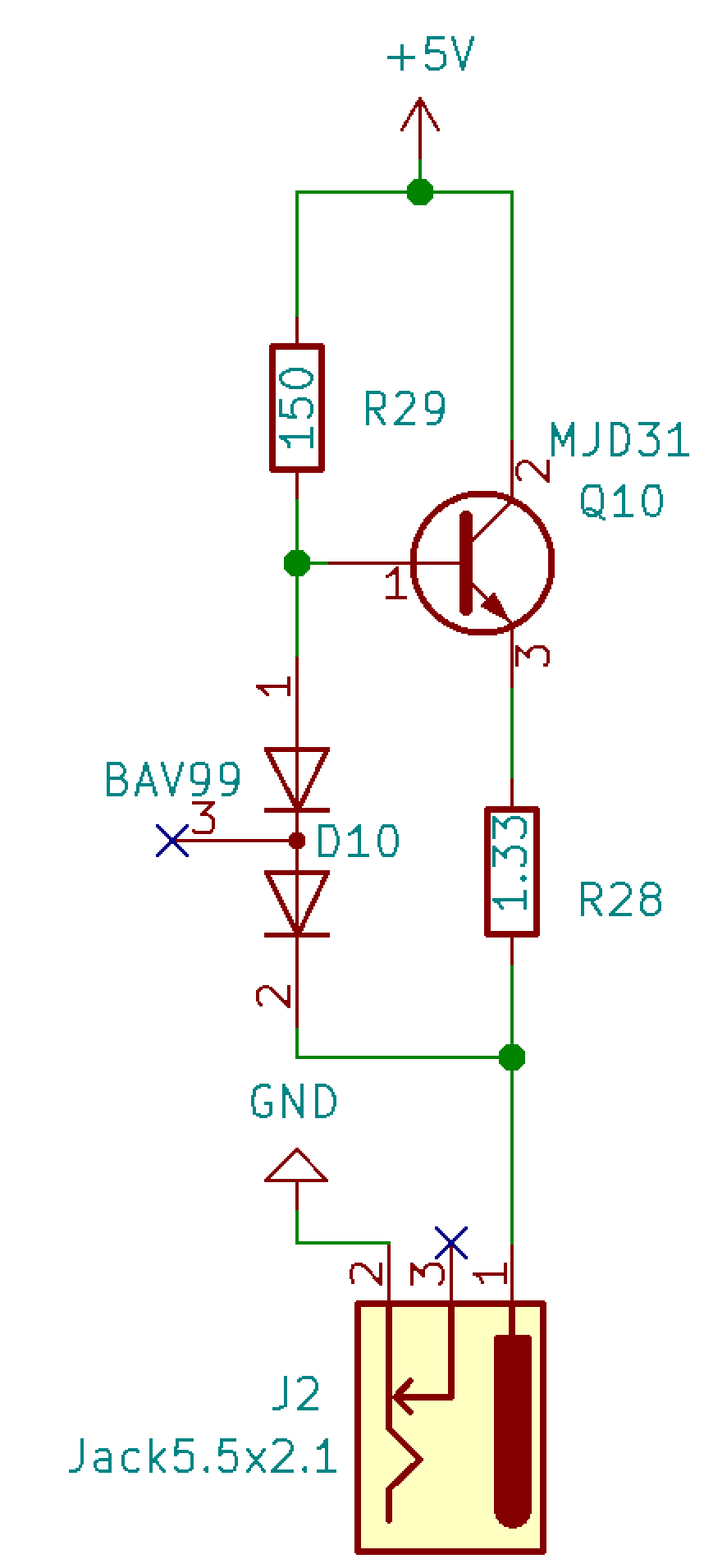
The current limit is set by the value of the current-sense resistor, R28, which is 1.33 ohms. When power is first turned on, the base of transistor Q10 is biased by R29, which turns on Q10 and allows a larger current to flow through Q10 from collector to emitter. The current flows through the current-sense resistor to the shamash supercap, which begins charging.
When the supercap first begins charging, it is essentially a dead short, except for its equivalent series resistance. If the current through the 1.33-ohm resistor R28 reaches ~450 mA or more, the voltage drop across R28 is above 0.6 V. When combined with the ~0.6 V voltage drop across the Q10 base-emitter junction, this means that the total voltage drop is more than 0.12 V and is enough to turn on the two diodes in D10. When D10 starts conducting, it reduces the current going into the base of Q10, which reduces the current going into the collector. Thus, the current ends up getting regulated so that i = V/r = 0.6V/1.33Ω = 450mA, give or take a bit. This will vary due to temperature variations and tolerances, but that’s close enough.
The current through a capacitor follows the equation i=C dV/dt, so when the capacitor is charged with a constant current, dV/dt = i/C = 450mA/0.5F = 0.9V/s. Thus it only takes a couple of seconds before the supercap is charged enough to turn on the LED.
Candles
The candle circuit (duplicated eight times) has more parts than it needed because I started to add another feature, but I needed to place an order for PCBs if I wanted them to arrive before Hanukkah was over. Thus, when it came to a choice of minimizing the BOM or maximizing the features, or having the...
Read more » Glenn.Kubota (gee.k)