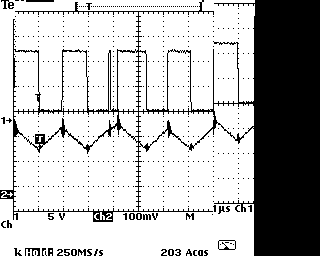
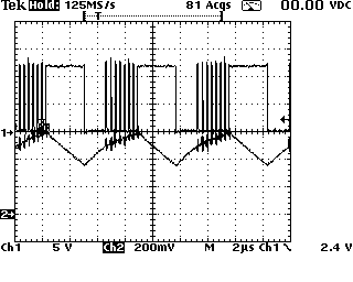
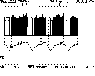
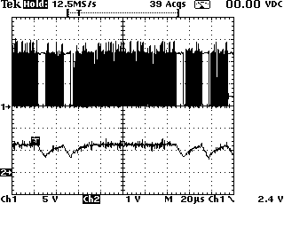
Here is a series of scope shots at different LED current Settings. All tests were done with 2 LEDs in series, 12V input supply to board. All of the scope shots show channel 1 as the voltage on the switch node and channel 2 as LED current. Wiring on the two LEDs was very short, around 3" each.

This scope shot shows board operating at a fairly low current setting. The LED current is oscillating around the setpoint cleanly and the switch node is mostly clean. Note the one noise spike on the switch node, just to the left of center. This spike occurs when the switch is turned on.

This scope shot shows the board operating at a higher LED current. Note the noise spikes on the switch node are more frequent and are corrupting the LED current somewhat.

This scope shot shows the board operating at a higher current setting. The noise on the switching node is very severe. You can see that it is changing the pulse widths on the switch node and the current waveform.

This is operating at the highest setting that my design is configured for. The noise has become so severe that the periodic switching has almost disappeared.
Testing with a single LED gives very similar results, but at different current settings.
I tried testing into a short circuit which is not a big problem because this is s current regulator. Even into a short circuit, the noise on the switch node appears.
At this point, I am waiting for the next rev PCB to come back from OSHPark. The next board rev has a lot more copper on the power, switch nodes and ground, as well as more capacitance on the power input. My expectations of success with this are not very high.
 Bharbour
Discussions
Become a Hackaday.io Member
Create an account to leave a comment. Already have an account? Log In.