I bought some aluminium angle and manufactured simple brackets to hold the motors in place. I used the linear rail shaft mounting bolts to also mount the motor bracket. This kept the motors nicely aligned and reduced the number of fixings required.
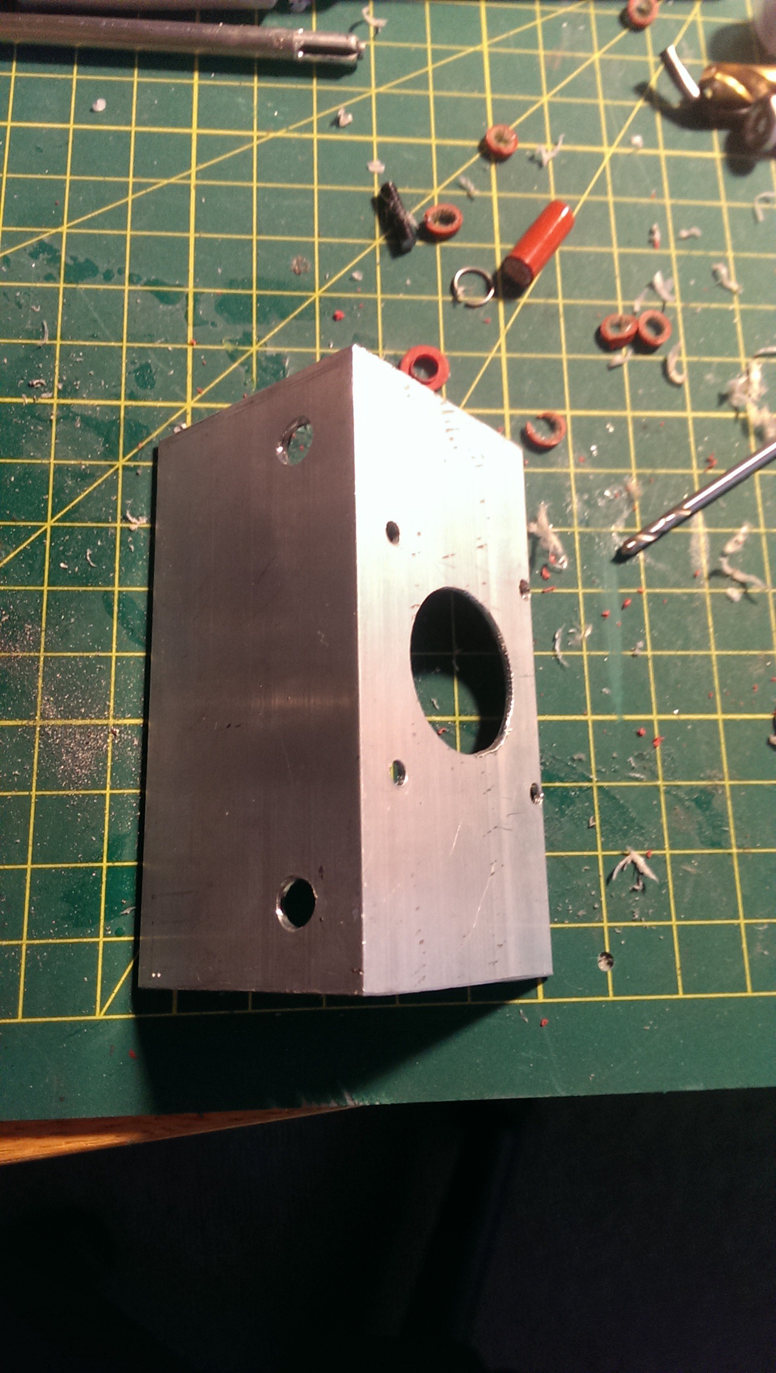
Nema 17 bracket
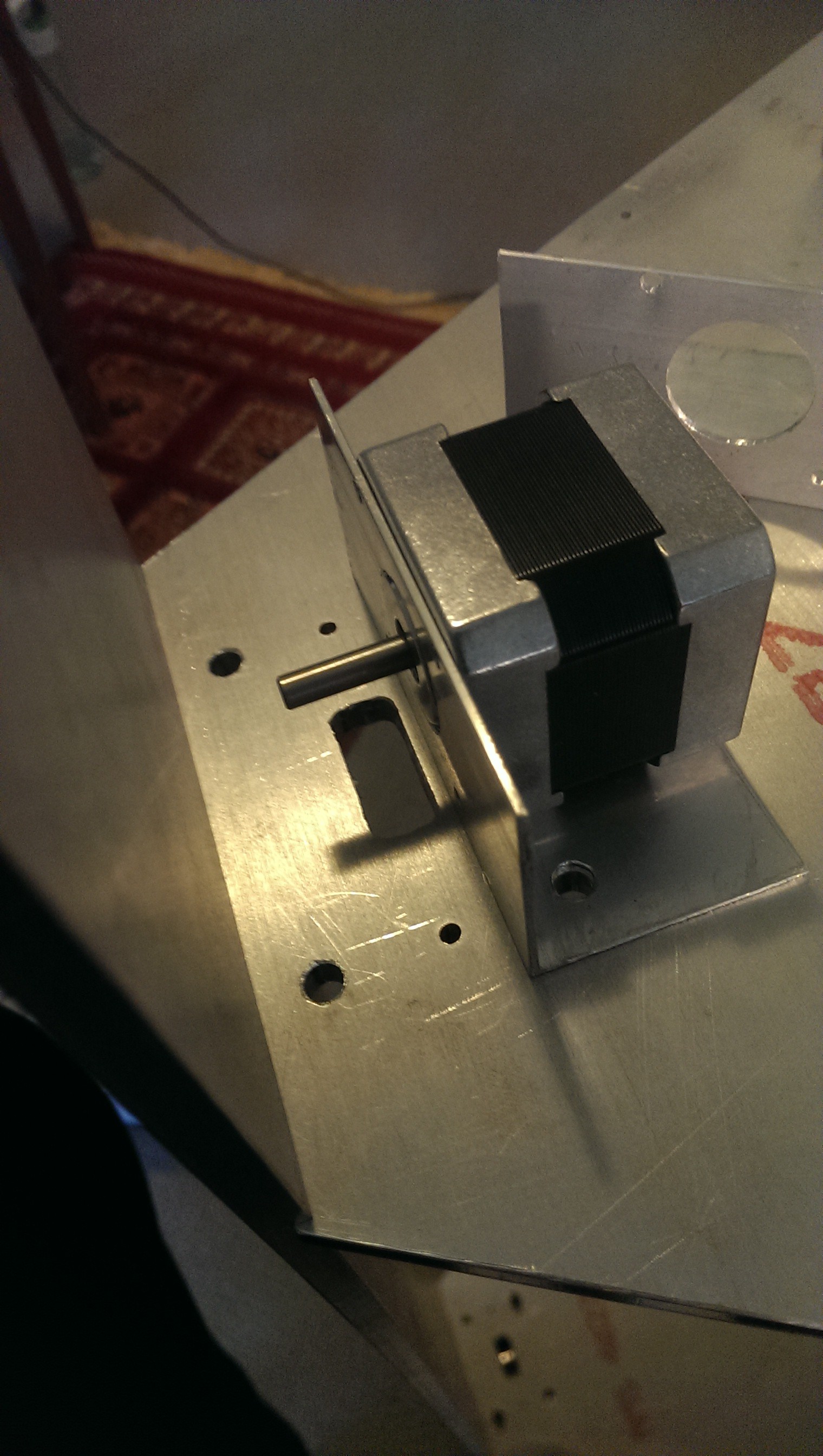
Sharing the hole with the shaft mounting bolts
I used a portion of chopping board to mount the top idler pulley. The chopping board also shared mounting holes with the shaft mounting bolts below. I drilled a 5mm hole through the edge of the chopping board and slid a shaft in through some flanged bearings. I was really happy with this neat solution.
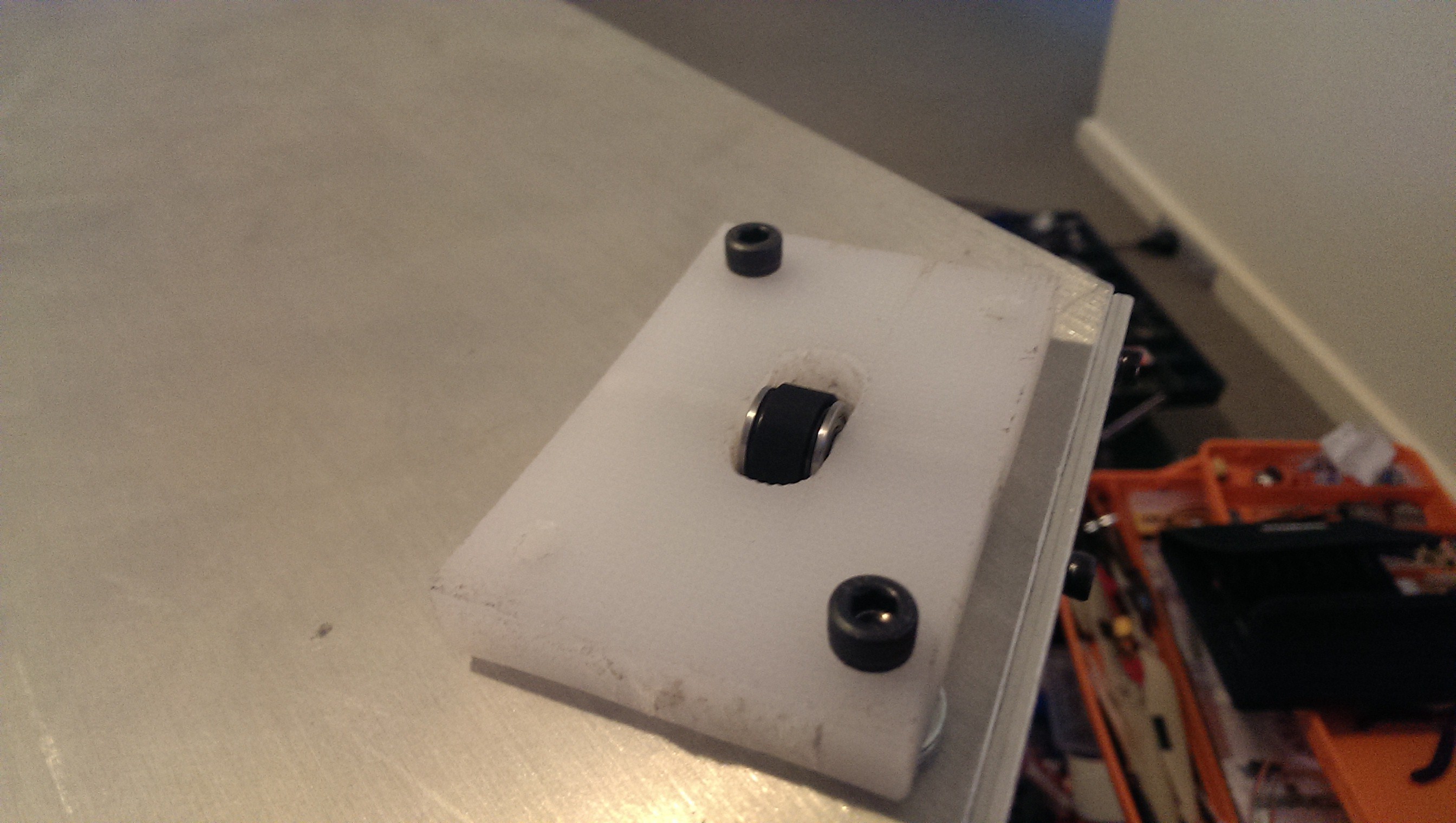
Idler pulley mounting blocks (two of four bolts installed)
I had seen a few designs with fancy (and often intricate)
belt tensioning mechanisms. I decided
that I would not have any mechanical adjustments for the idler bearing and rely
on an in-belt tensioning spring. I had
seen many printers use this method and liked the simplicity. A few clothes pegs were sacrificed for their
springs.
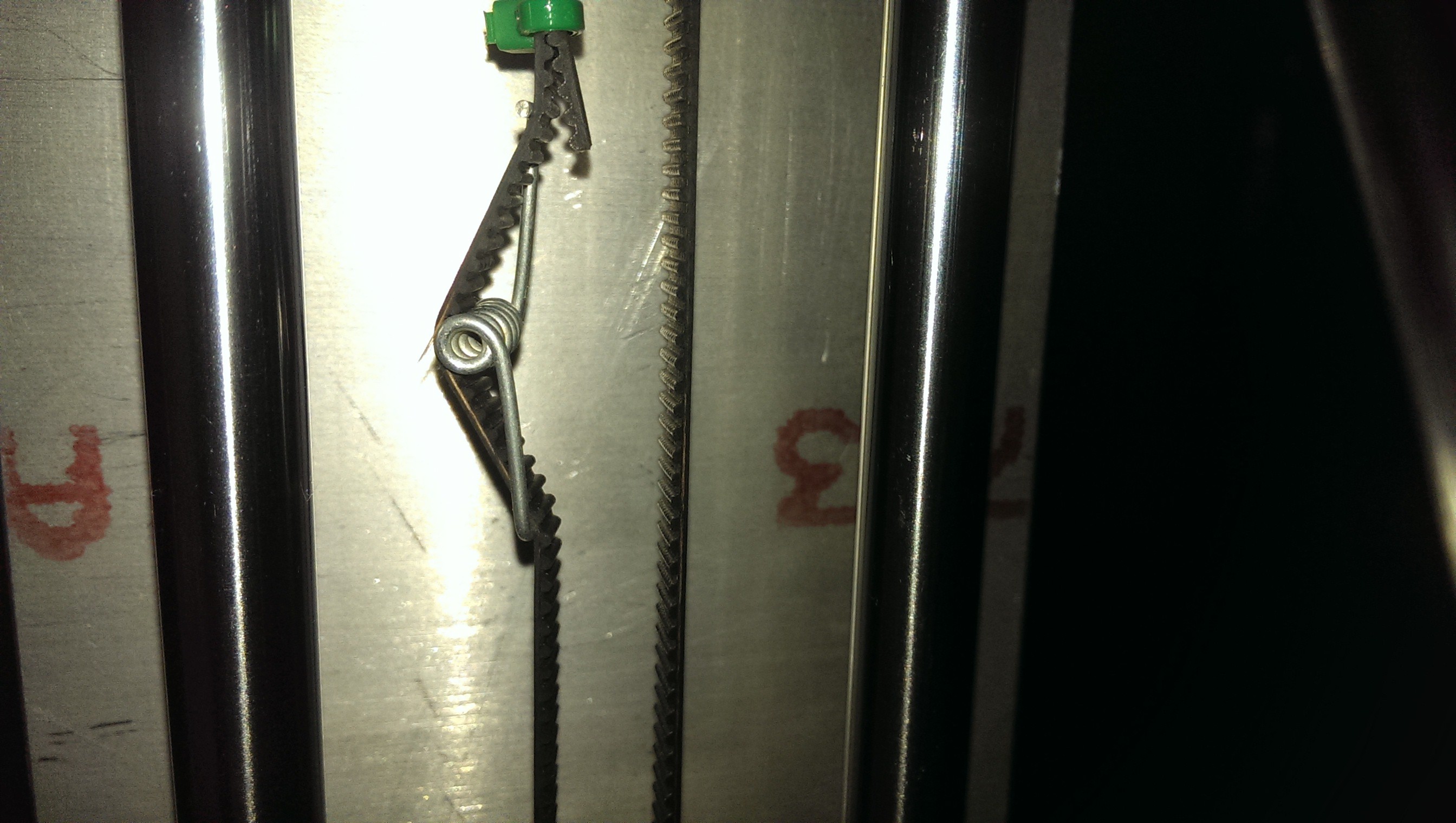
Clothes peg spring
Here is a test where I powered up a stepper motor for the first time.
It's alive!
The Greg’s Hinged Extruder was mounted upside down under the
top plate using an aluminium bracket. I
chose a mounting position that would allow for an unobstructed filament path.
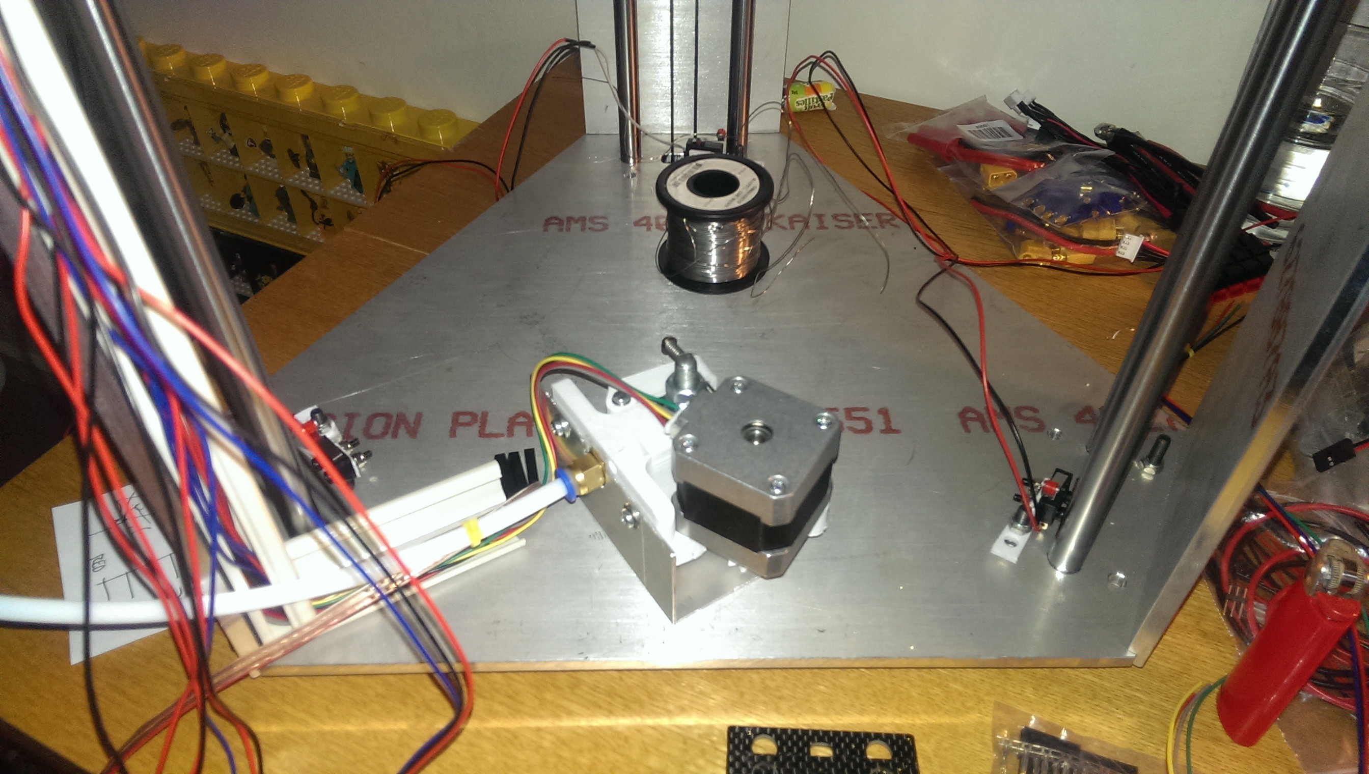
Extruder Positioning
Discussions
Become a Hackaday.io Member
Create an account to leave a comment. Already have an account? Log In.