-
Automatic Crash Detection
03/31/2017 at 13:24 • 0 commentsAfter upgrading to zero-backlash magnetic ball links I found that occasional print crashes were now a major problem. With the old fixed ball links the printer would generally crash and keep printing in the air just above the object. When a magnetic ball lets go the end-effector is hanging limp and continues to be dragged through the print and across the heated bed. This can cause some serious damage.
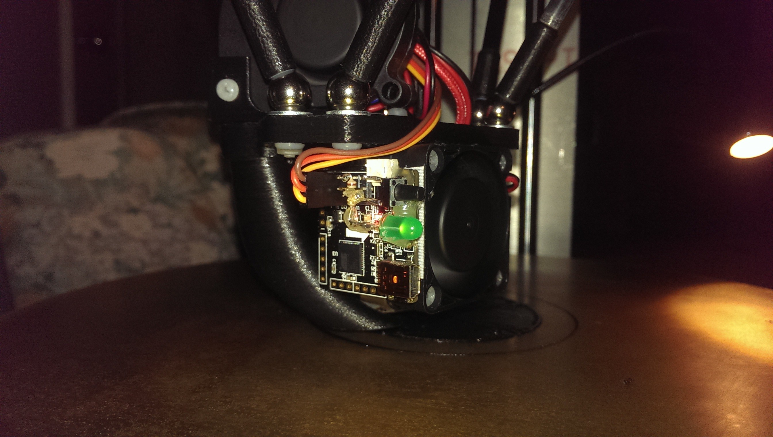
A friend of mine suggested using a small IMU chip to detect a sudden rotational (GYRO) change. I dug through my junk box and found an old NanoWii Multirotor Flight Controller. I modified the Arduino code and added a status LED with arming button. I was able to use the 5V, GND and a GPIO pin to provide an identical interface to the printer as a normal endstop. It was then simple to modify the printer configuration to perform a pause/suspend when the signal wire pulsed high. The arming button allows the sensor to be easily disabled for maintenance or enabled after a crash. An added bonus of using only the gyroscope is that the NanoWii can be positioned in any convenient orientation on the end-effector - we are only looking at spikes in rotation.
![Test mounting position]()
Test mounting position
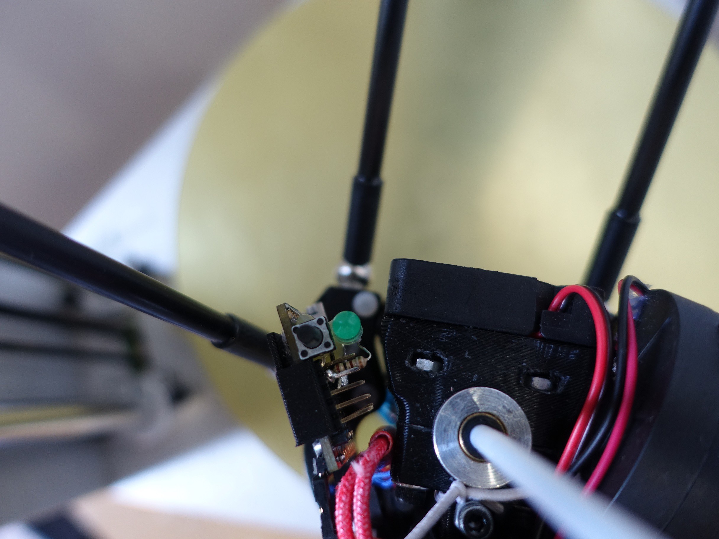
![New mounting position]()
New mounting position
This video shows me first arming the NanoWii then triggering a "crash". I have some “on pause” G-Code to lift up the end-effector and turn off the heaters.
With this system, I am able to resume most prints that have a crash, provided that the stepper motors didn’t skip steps. Due to the magnetic balls, it is more likely that they let go before steps are skipped, resulting in a high recovery rate. As of writing, Smoothieware only allows jogging and filament change while in the suspended state. If a home command is issued to fix any skipped steps, the print cannot be resumed.
I am really happy with how effective this solution is. There are no mechanical parts required and the IMU only needs a spare endstop input to function.
-
Linear Bearing Upgrade
03/31/2017 at 13:07 • 0 commentsThe first bearings I bought were cheap LM12UU linear ball bearings. They worked fairly well and were reliable. They did however have some slop and were noisy. I started to strive for more quality in my prints and noticed sometimes there would be vibration lines in the surface finish. This was mainly due to the slop in the bearings.
When I upgraded to magnetic ball joints I also tried to upgrade the linear bearings. I thought that longer bearings would help with the slop and result in more rigid mechanics. I bought a set of 57mm LM12LUU long linear bearings to try.
The bearings made a huge difference to the rigidity of the delta mechanism - so huge that they introduced even more resonance! They were also quite heavy so some of the benefit was lost having to print at slower speeds/accelerations. I also noticed the motors were running hotter as the friction was higher.
![Super rigid]()
Super rigid
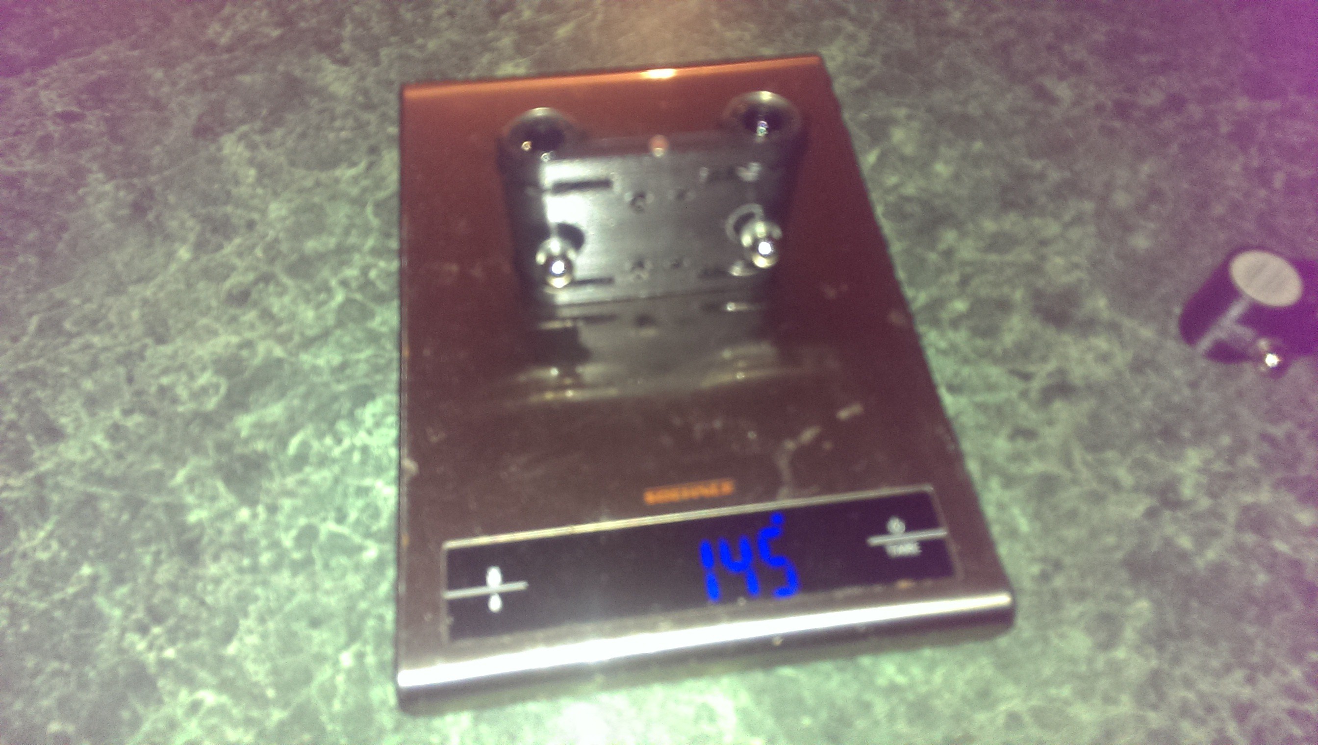
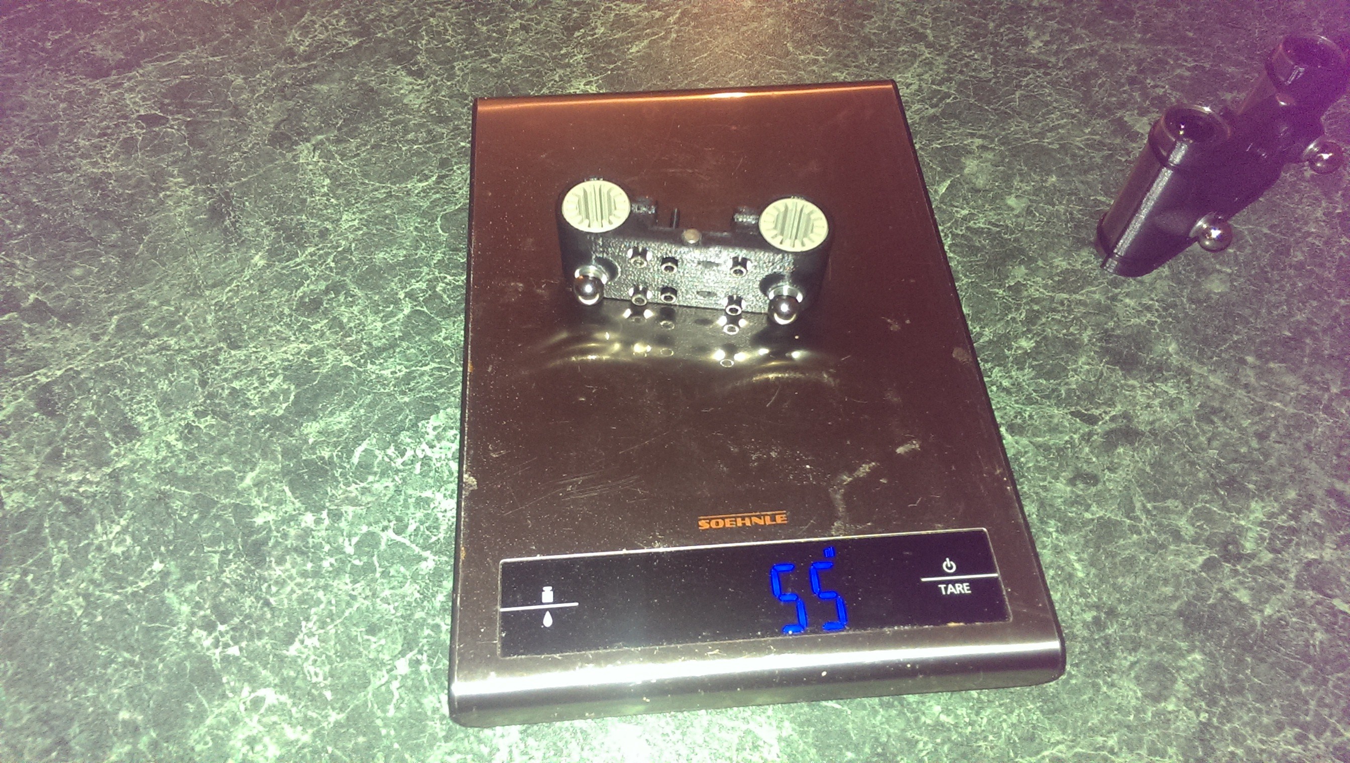
Igus Drylin Polymer bearings were becoming quite popular so I bought a set to try. They require a certain amount of pre-loading so I re-designed my sliders to incorporate a clamp mechanism. Here are some terrible quality photos of the weight difference between the 57mm LM12LUU sliders and the polymer bearing sliders:
![145g]()
145g
![55g]()
55g
They are super quiet, light and very smooth, though they still have a bit of slop. I’ve deemed this an acceptable compromise. You can hardly hear the printer while it is running!
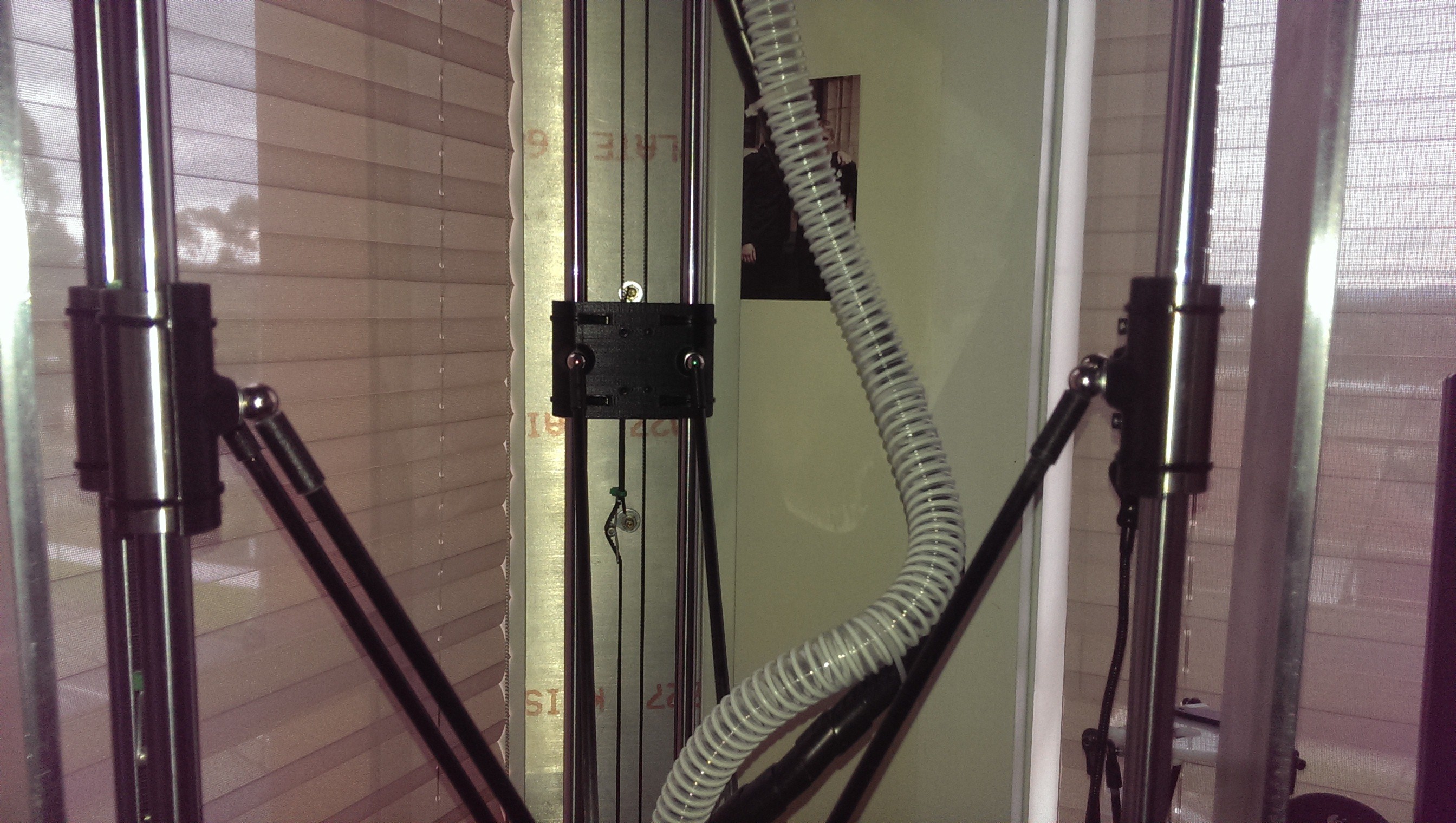
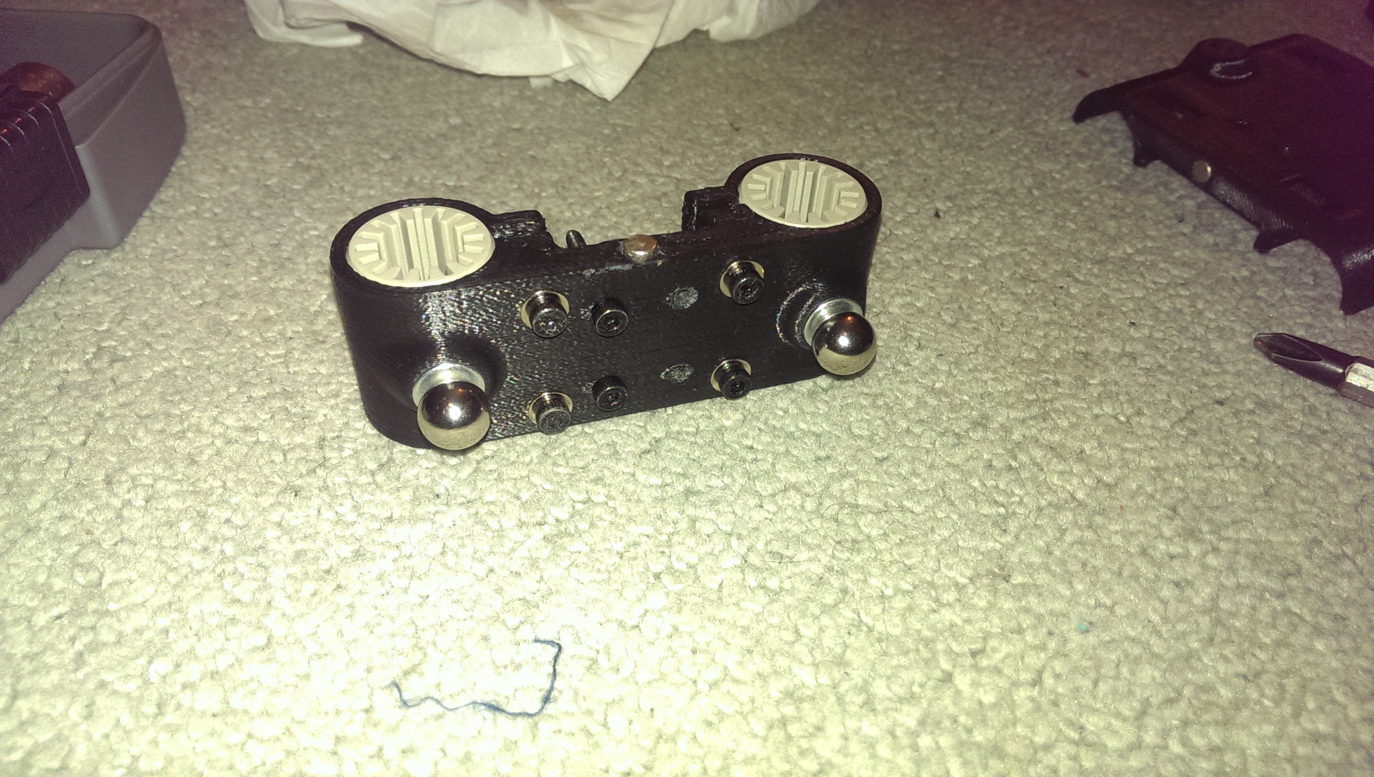
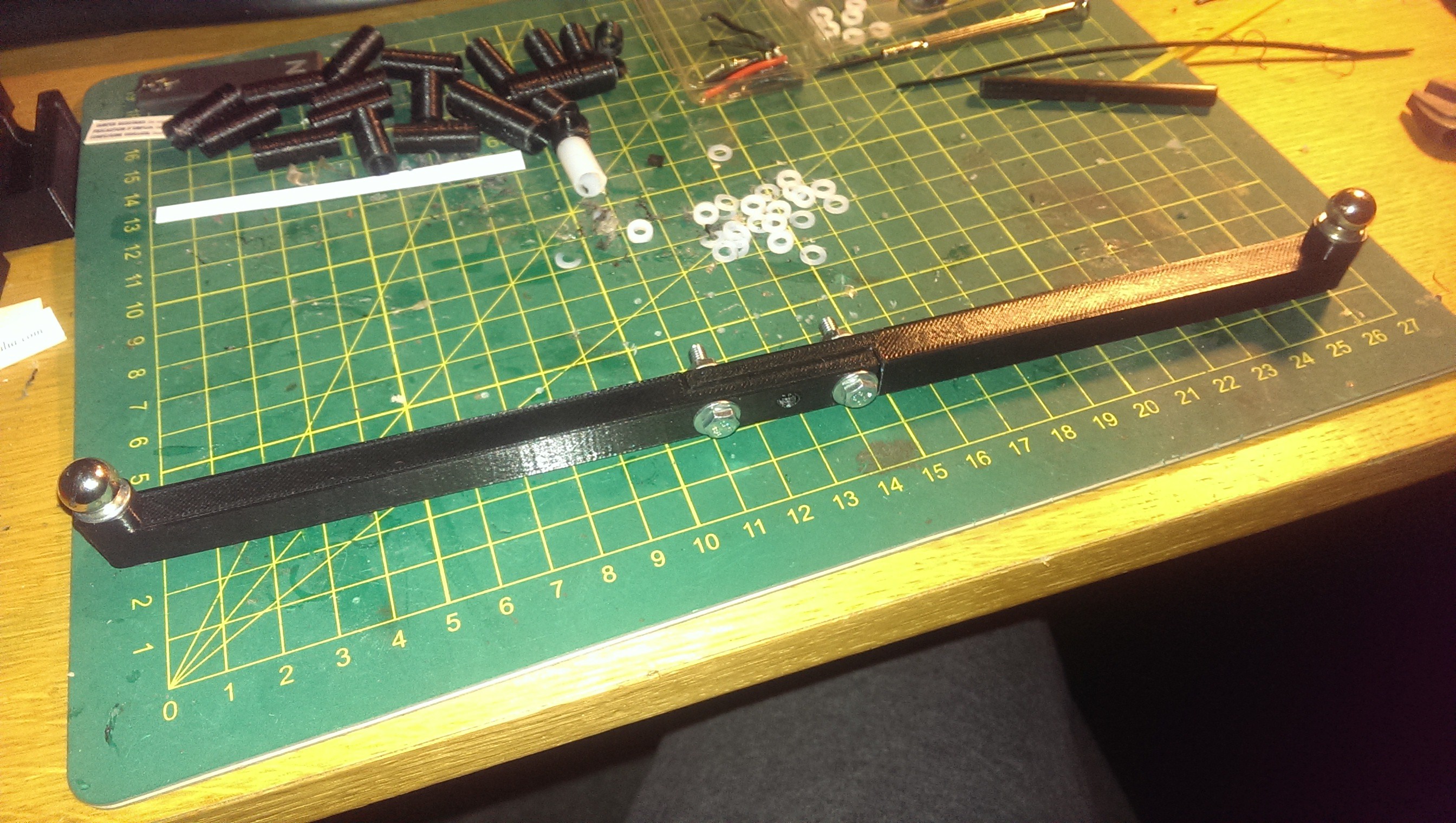
![New lightweight silent sliders]()
New lightweight silent sliders
![The belts loop over the two protruding bolts. Also notice the captive nuts.]()
The belts loop over the two protruding bolts. Also notice the captive nuts.
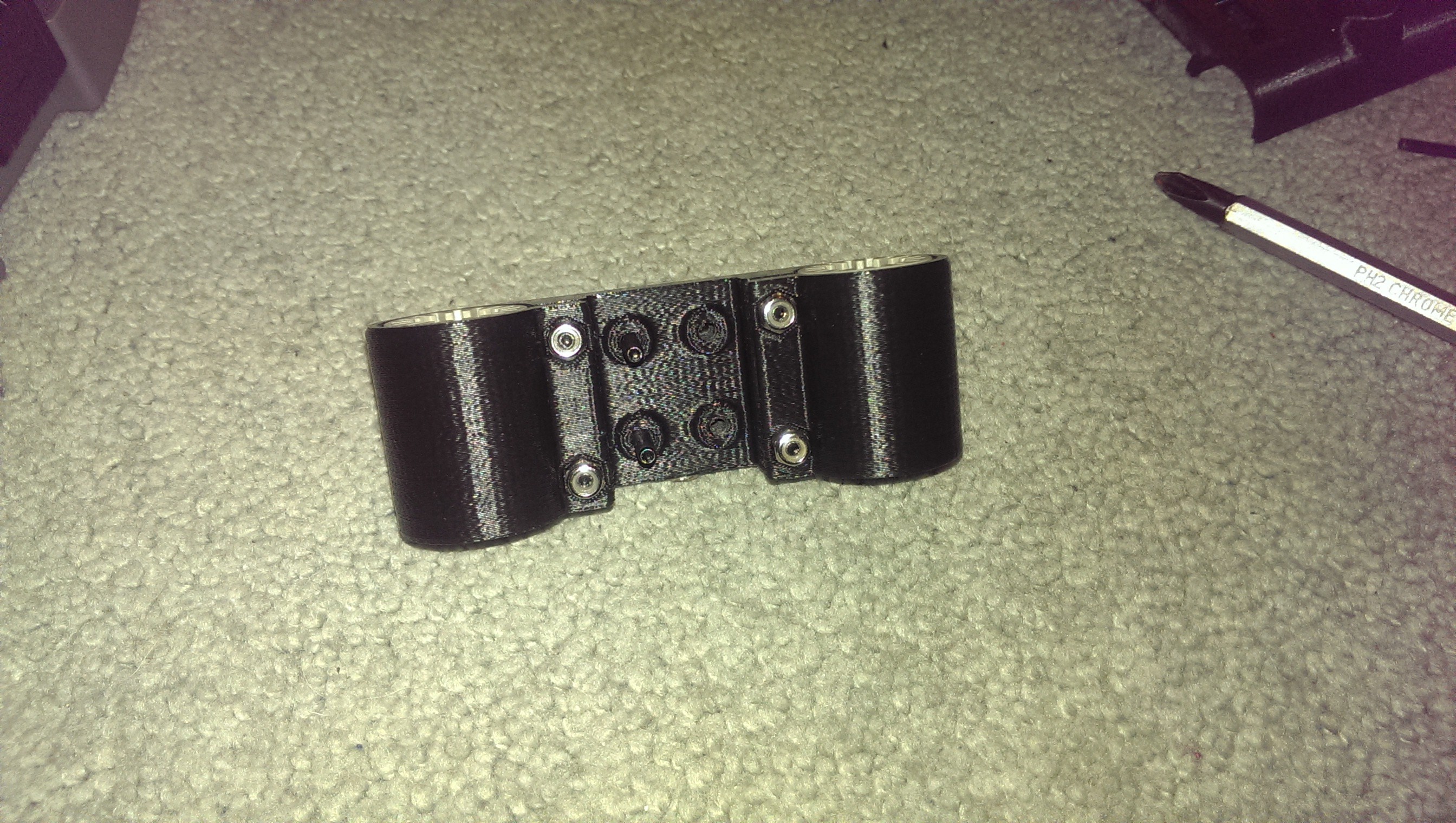
![Very neat]()
Very neat
-
Z Probe
03/31/2017 at 12:58 • 0 commentsShortly after I started printing there were developments in auto calibration/levelling/tramming. Probing with the version of Marlin I had was in its infancy so I didn’t get very far.
I had always levelled the bed using thin paper and pre-set positions at the base of each tower. I had designed the hall effect endstops to be slightly adjustable so it was fairly quick and painless to calibrate. It would normally take about 5 minutes to get an acceptable calibration.
When I upgraded the printer controller in 2016, I thought I would give Z probing another go. Around the same time, I replaced the perfectly flat glass heated bed plate with an aluminium plate laminated with PEI sheet. The new heated bed was very flat but not as perfect as the glass. I was very interested in using grid-mesh bed levelling to try and compensate for the irregularities.
I purchased a small infrared gate sensor and, using a pen spring and 2.5mm rod, designed a compact Z probe. I chose the infrared sensor in the hope that it would be more repeatable. The spring was held in a little channel and secured with a terminal screw from a salvaged mains terminal strip. I printed a tiny little flag to go on top of the shaft which would pass through the infrared sensor.
I decided that automatic probe retraction was not really necessary considering tramming would not be done very often. The added complexity of a probe retract mechanism was overkill for me. The probe could be engaged by lifting it slightly and pushing it inwards. To disengage, it could be lifted then pulled outwards.
![Probe retracted]()
Probe retracted
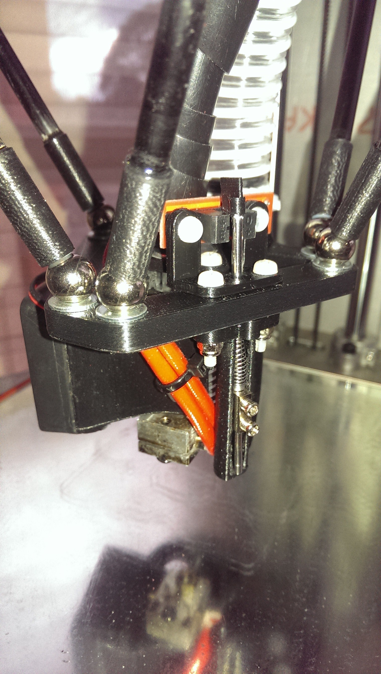
The probe worked very well mechanically. Unfortunately, the final tramming result did not go very well. Any variation in the delta mechanics can cause the end effector to become slightly out of parallel with the heated bed. The variations were caused by slight misalignments of the magnetic balls, imperfections in the printer frame and the Bowden tube exerting a twisting force on the end effector. As the probe was offset from the nozzle about 25mm, this meant that the trigger point could vary depending on where the end effector was on the bed. It wasn’t much but was enough to cause the nozzle to drag on one area of the bed and remain airborne in another area.
My solution to this was to use the nozzle itself as the Z probe. This would eliminate the offset and hopefully cancel out any mechanical imperfections or twisting of the end effector.
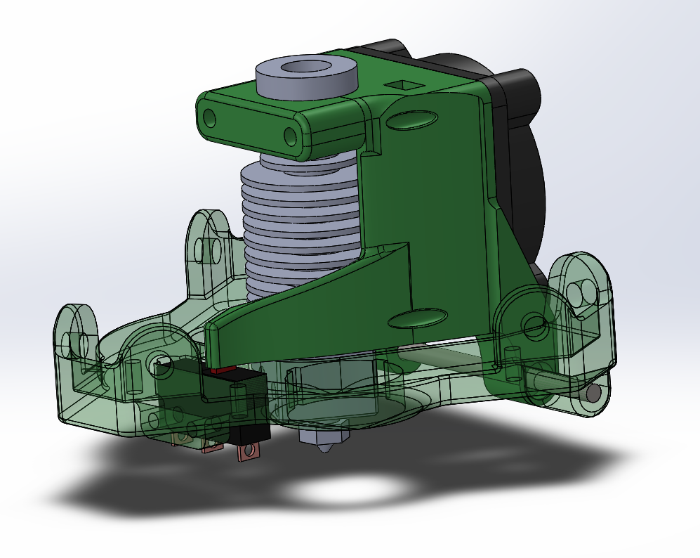
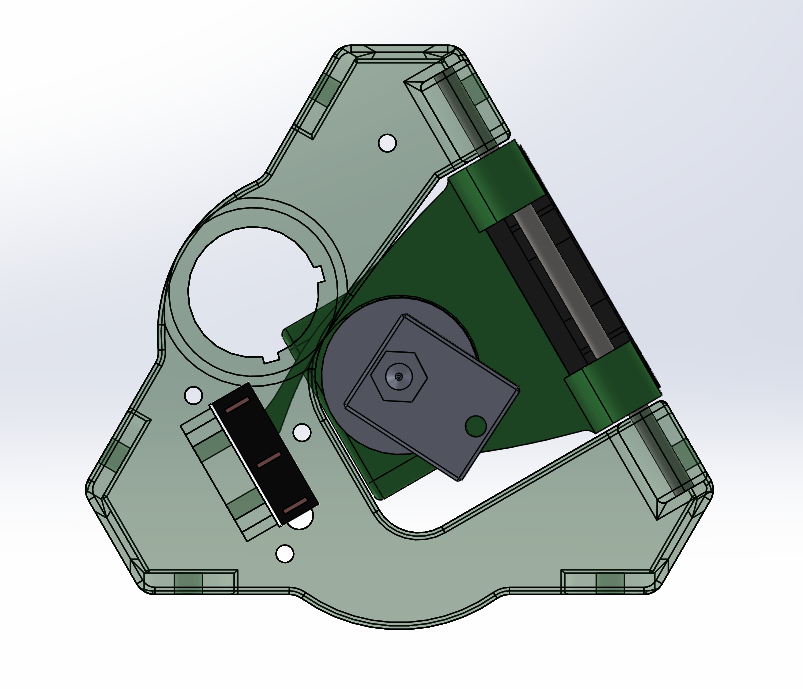
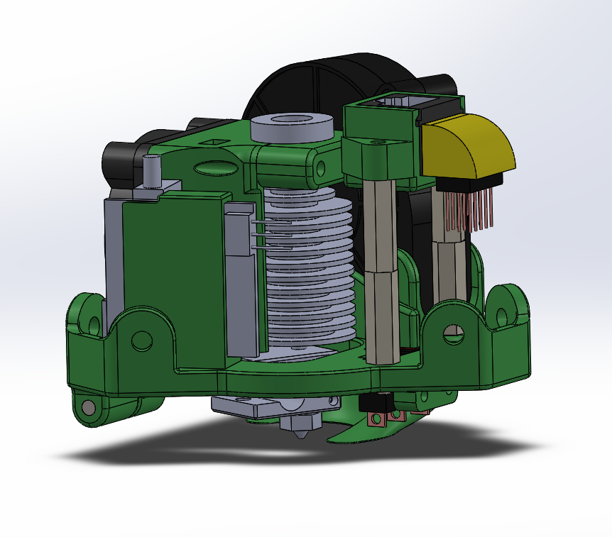
I designed many prototypes of a hinged extruder that would tilt slightly when pressed against the bed. I first utilised the existing infrared gate sensor but later moved on to a simple microswitch. I also had to consider how to fit the cooling fans and cable connections within a compact footprint. It is hard to see the mechanism in photos so here are some CAD snips:
![Hinged extruder and microswitch]()
Hinged extruder and microswitch
![View from underneath]()
View from underneath
![Final assembly]()
Final assembly
Z probing now works very well and is reasonably repeatable.
I run the following G-code assigned to a custom menu item:
M190S60; Set bed temp to 60 degrees C
G32; Do endstop offset and delta radius calibration
M500; Save settings
G31; Do delta grid probes across the bed
M374; Save grid to SD card
M500; Save settings
G28; Do home
G0Z5F6000; Move nozzle 5mm above expected bed hight
G38.3Z-10; Slowly lower nozzle to detect bed and stop
G91; Switch to relative movements
G0Z0.7; Raise nozzle to perfect Z height - where microswitch has released plus a little extra
G90; Switch to absolute movements
M306Z0; Save Z height offset
M500; Save settings
G28; Do home
G0Z75F6000; Park just above the middle of the bed
M190S0; Turn off the heated bed
After this routine, the printer is in “tram”.
-
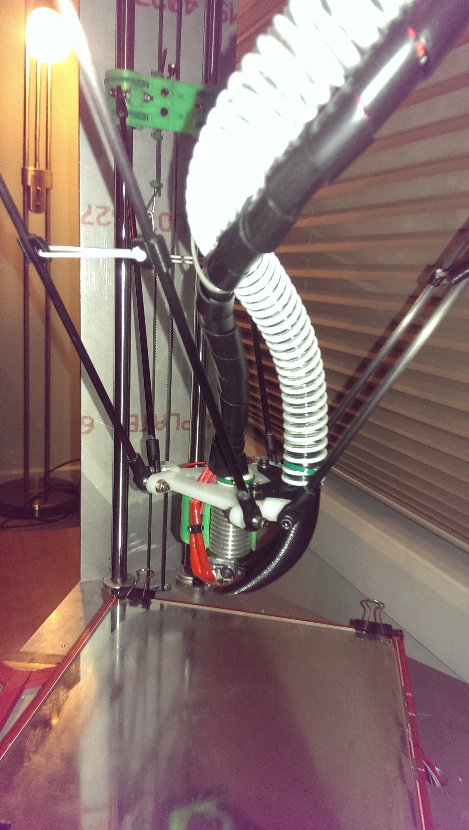
Magnetic Ball Joints
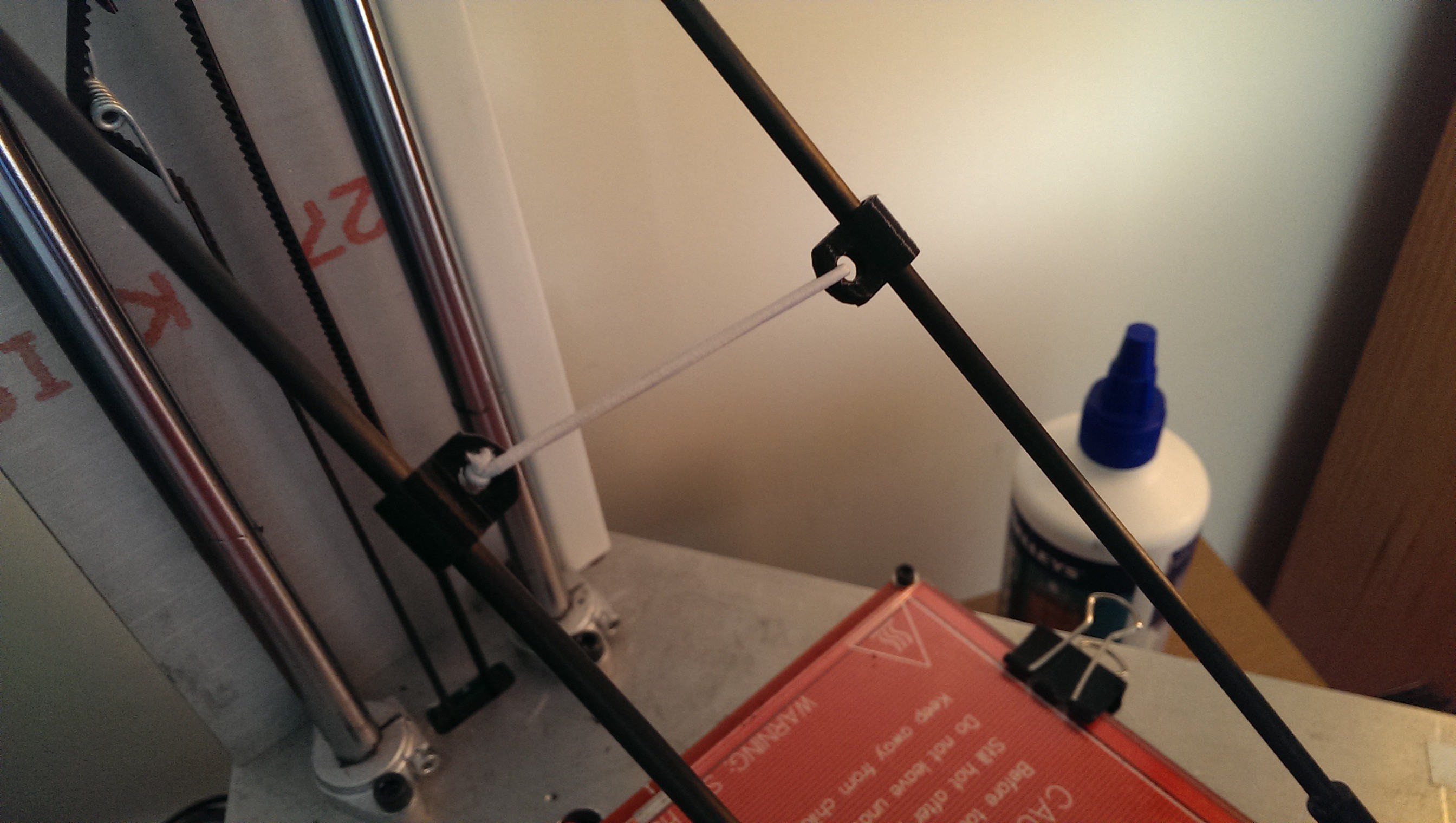
03/31/2017 at 12:57 • 0 commentsOne of the causes of slop in my printer linkages was the Traxxis ball joints. They have quite a lot of play unless they are pre-loaded. I worked around this by using elastic to pull the two arms together. This worked surprisingly well but showed slight movement at higher speeds.
![Linkage arm pre-loading]()
Linkage arm pre-loading
As with most of my printer upgrades, I usually see some cool idea somewhere on the internet and think “That would be great on my printer”.
Magnetic ball joints have zero backlash. The magnet keeps tension on the ball and pre-loads automatically. I really liked the idea and thought it would be a good challenge to manufacture accurately. It would also fulfil another idea that I had in the back of my mind - easy interchangeable end-effectors! I could quickly swap out the print head for an engraver, laser or pen plotter.
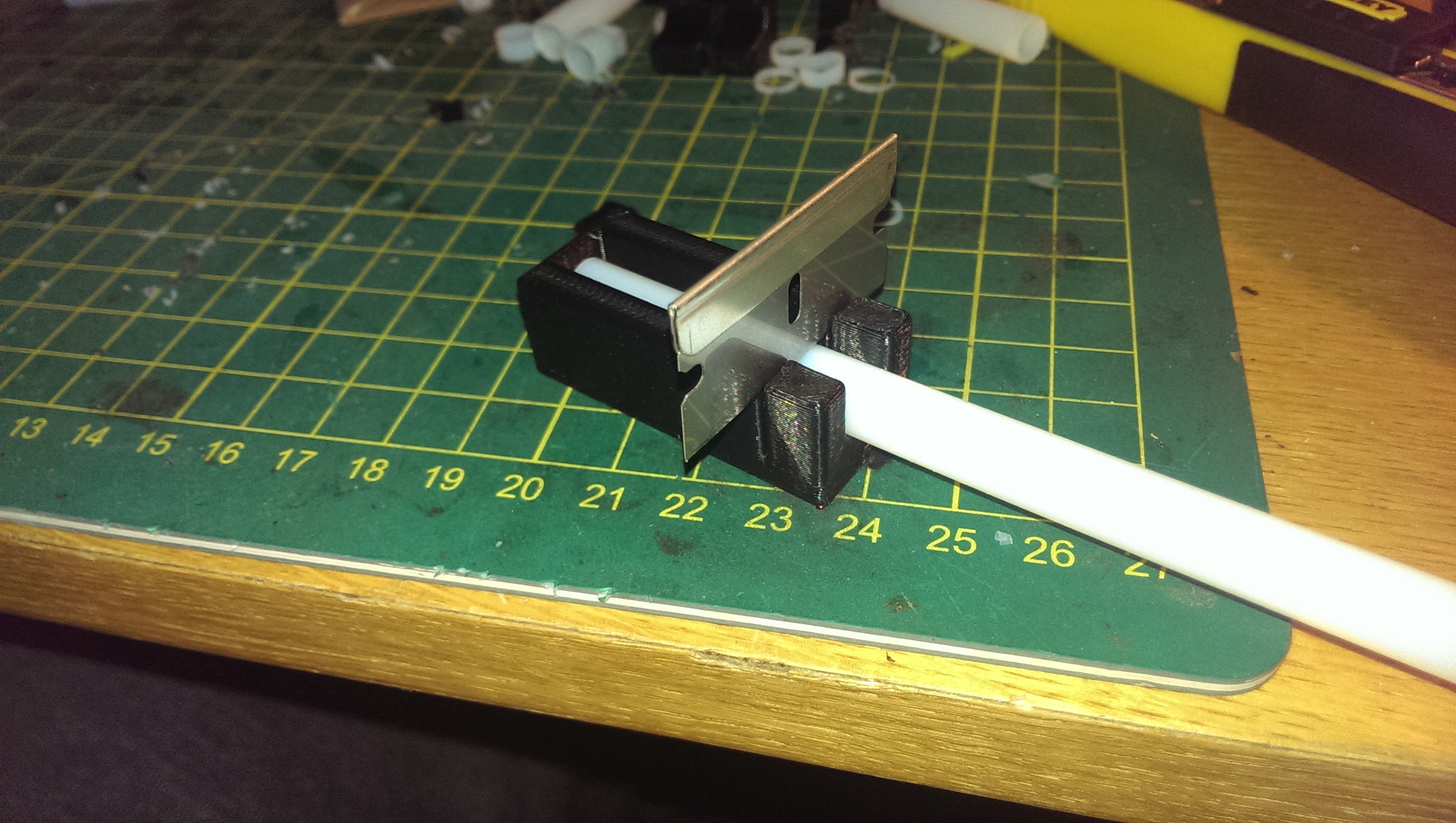
I started with some 6mm x 10mm cylindrical Neodymium magnets and 6mm carbon fiber tube. I printed some small tubes with an inner diameter of 6mm. These were slipped over the magnet and tube to hold them aligned. I sliced some PTFE washers from an old 6mm bowden tube. A printed jig ensured an accurate cut.
![Printed mitre box]()
Printed mitre box
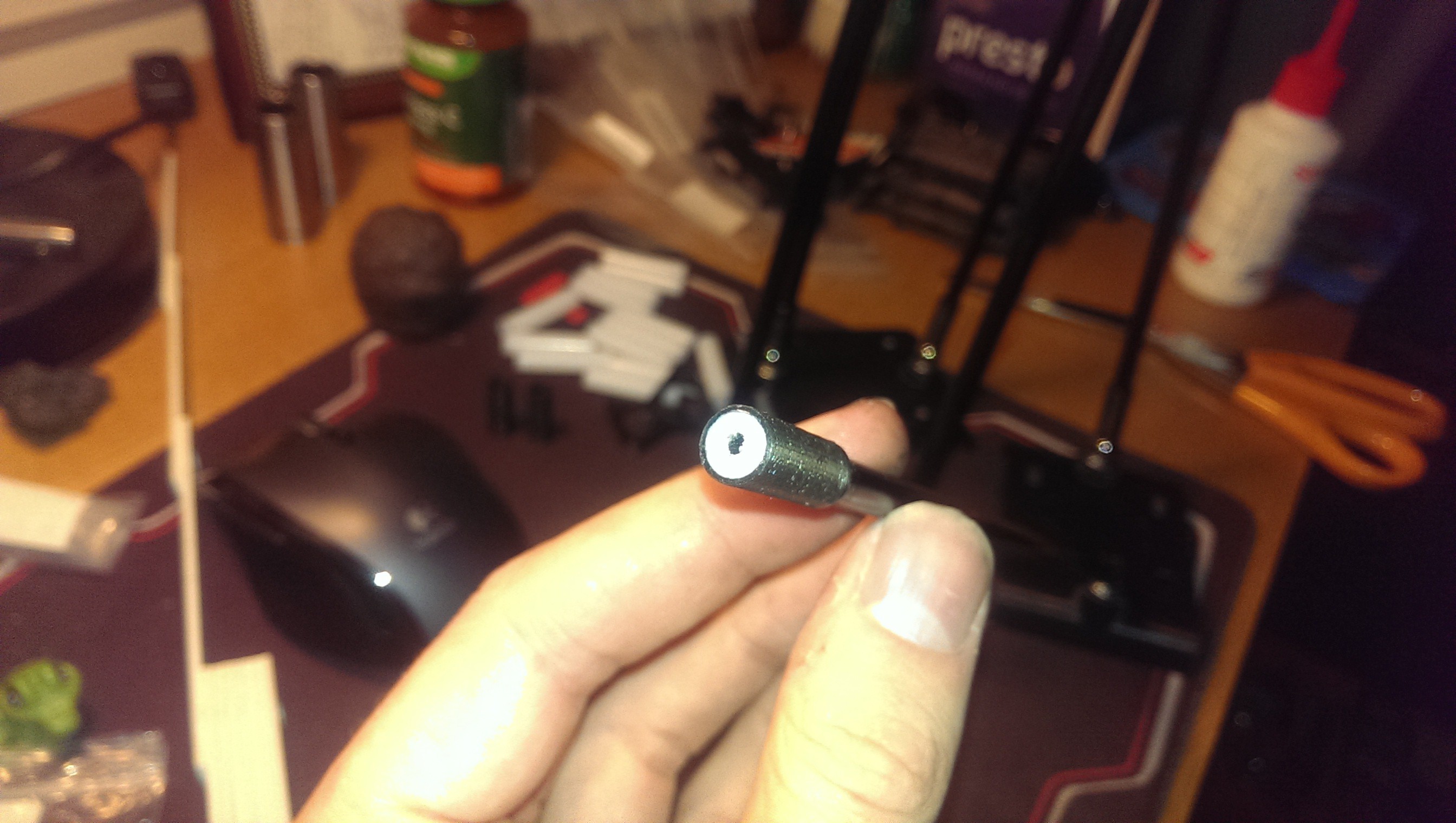
The PTFE washers were epoxied in the end of the printed tube between the magnet and ball. PTFE washers provide a low friction interface and prevent the magnet from touching the ball.
![PTFE washer, magnet and tube]()
PTFE washer, magnet and tube
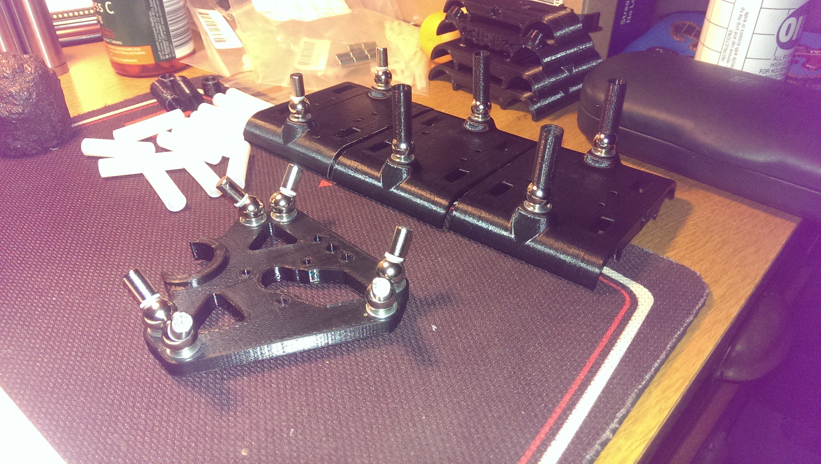
I had to print a new end-end effector and vertical sliders to incorporate 10mm threaded steel balls.
![Testing PTFE washers]()
Testing PTFE washers
I assembled only one end of six arms and allowed the epoxy to harden. I then printed a jig to ensure that the other end of each arm would be glued at the same length.
![Precision jig]()
Precision jig
The rods turned out well and the delta mechanics were extremely rigid. There was no backlash at all. The main issue that arose from the upgrade was when the magnets let go. The printer wouldn’t know if a ball link released and the end effector would be flopping around making a mess. This was soon to be rectified with another upgrade…
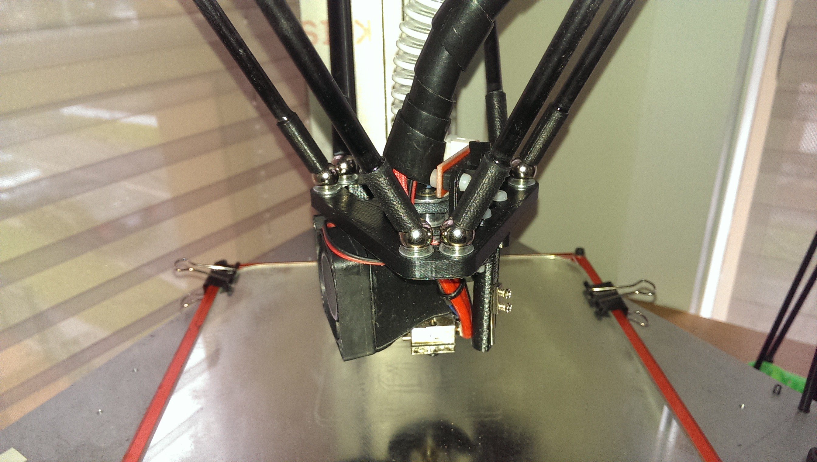
![The power of magnets!]()
The power of magnets!
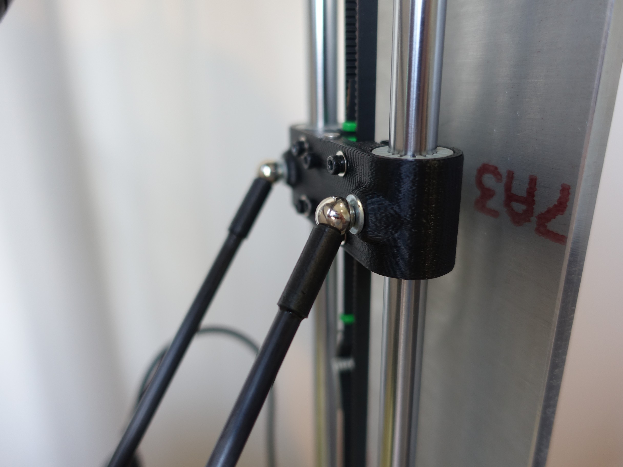
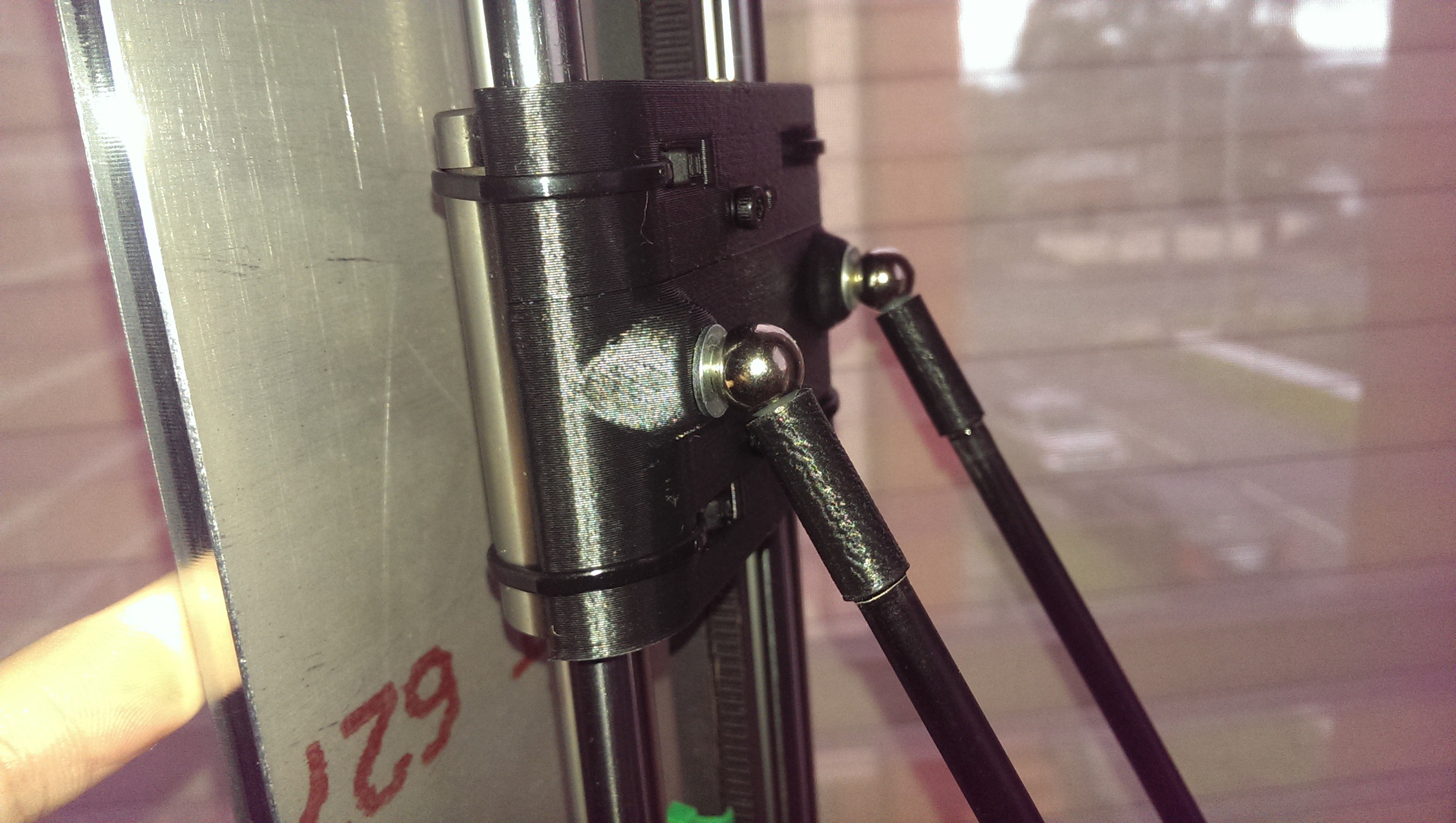
![New vertical slider]()
New vertical slider
-
Mains Powered Heated Bed
03/31/2017 at 12:56 • 0 commentsThe initial build used the MK2B heated bed that came with the electronics kit. There were a few round beds available but they didn’t fit in my budget at the time. I’d had a lot of success printing PLA with diluted PVA glue on glass. I wanted to increase the size of the bed to take advantage of my printer’s reach and also wanted to try something less messy. I’d started hearing about people using PEI (Polyetherimide) sheets with great success.
My plan was to get some aluminium sheet, laminate PEI on top and glue a silicone heater to the underside.
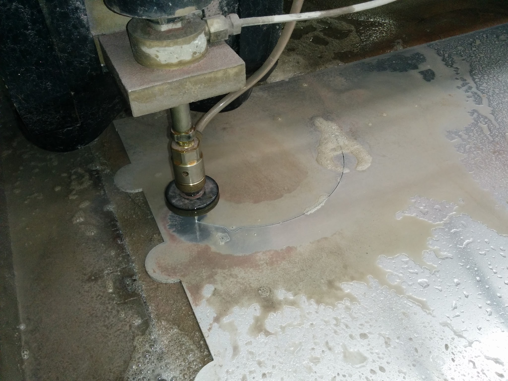
I called up my friend who helped me manufacture the main printer frame. He had access to a water jet cutter at his work and was willing to cut a round bed from aluminium. I designed a circular bed to be cut from 5mm aluminium with a radius of 280mm. I figured this would be thick enough not to warp when heated.
![Water jet cutting]()
Water jet cutting
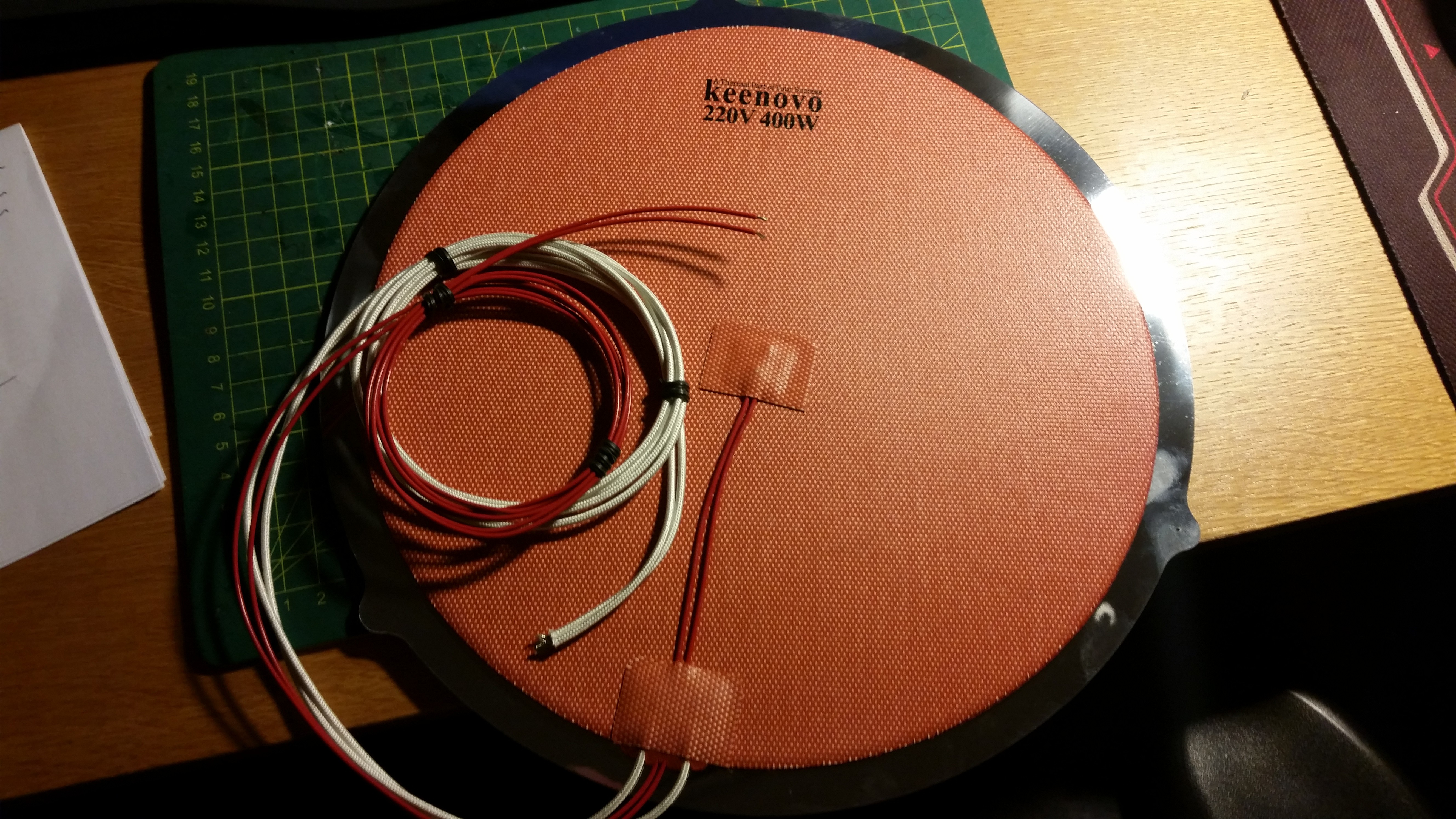
The next problem was heating. It becomes quite inefficient to heat up such a large area using a 12V supply. A considerable amount of current is required that can be difficult to control efficiently. A few people online had started using mains powered silicone heater mats driven by solid state relays (SSRs). This solution seemed pretty good for me. There’s less load on the printer power supply as the printer is more efficient using the mains power directly. I did some googling and found an eBay store (Keenovo) that manufactures custom silicone heater mats. They even include an adhesive backing and built-in thermistor.
![New heated bed]()
New heated bed
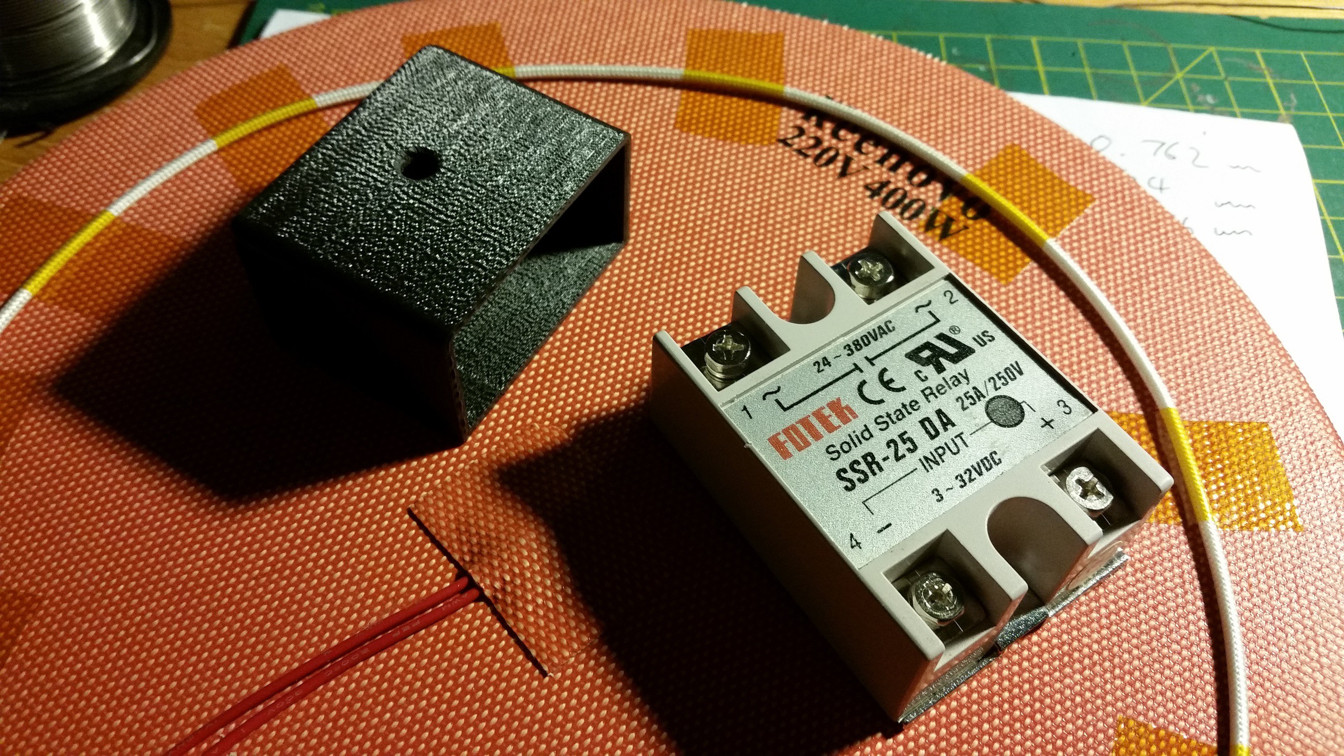
![SSR and printed end cover]()
SSR and printed end cover
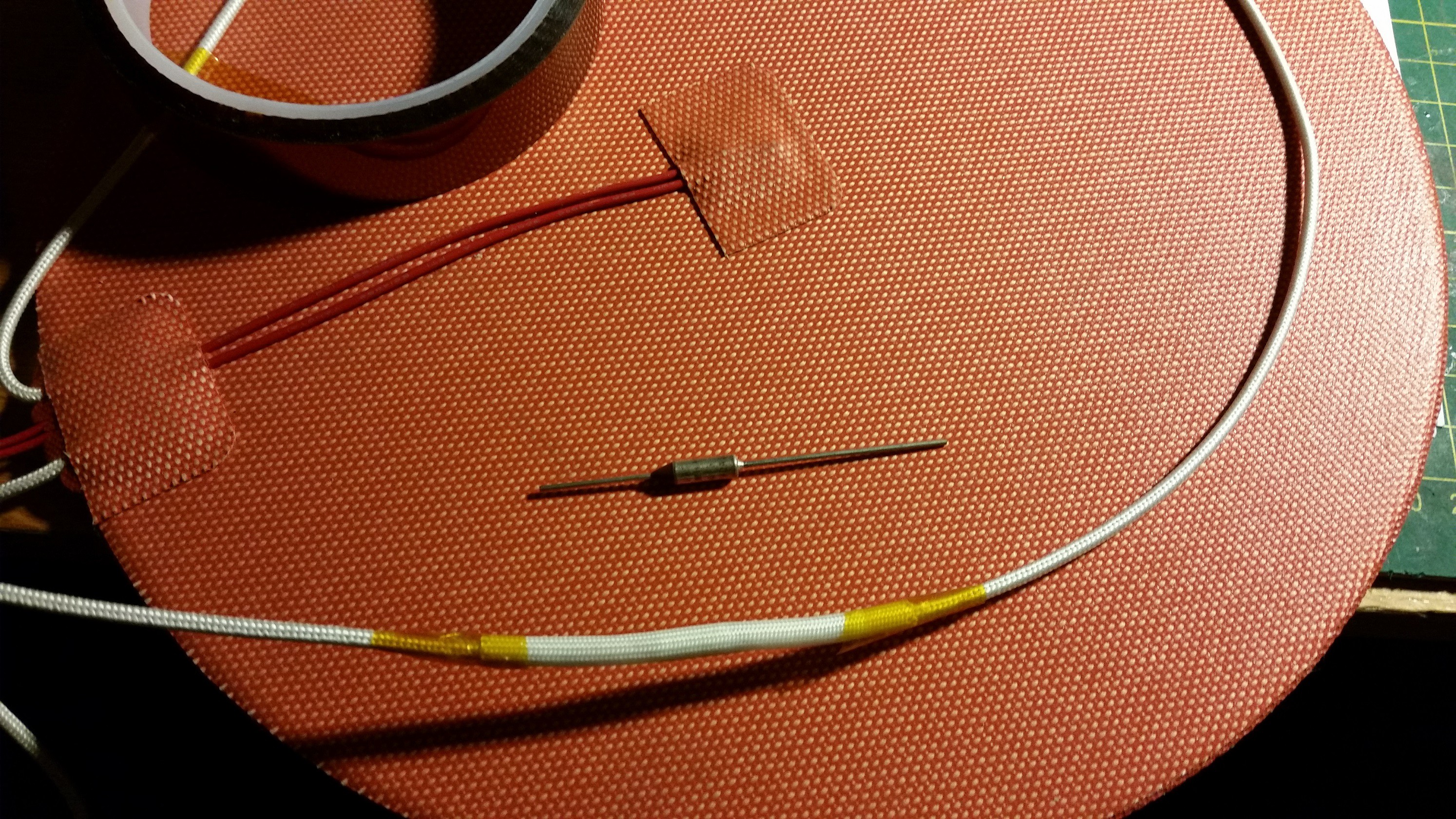
For thermal runaway protection, I decided to use a 128°C (262°F) non-resettable thermal fuse. There were some self-resetting fuses available but I didn’t want to risk getting into some type of temperature cycle. Once the bed temperature exceeds the fixed limit these fuses will open permanently. The only way to reset is to replace it entirely.
![In-line fuse]()
In-line fuse
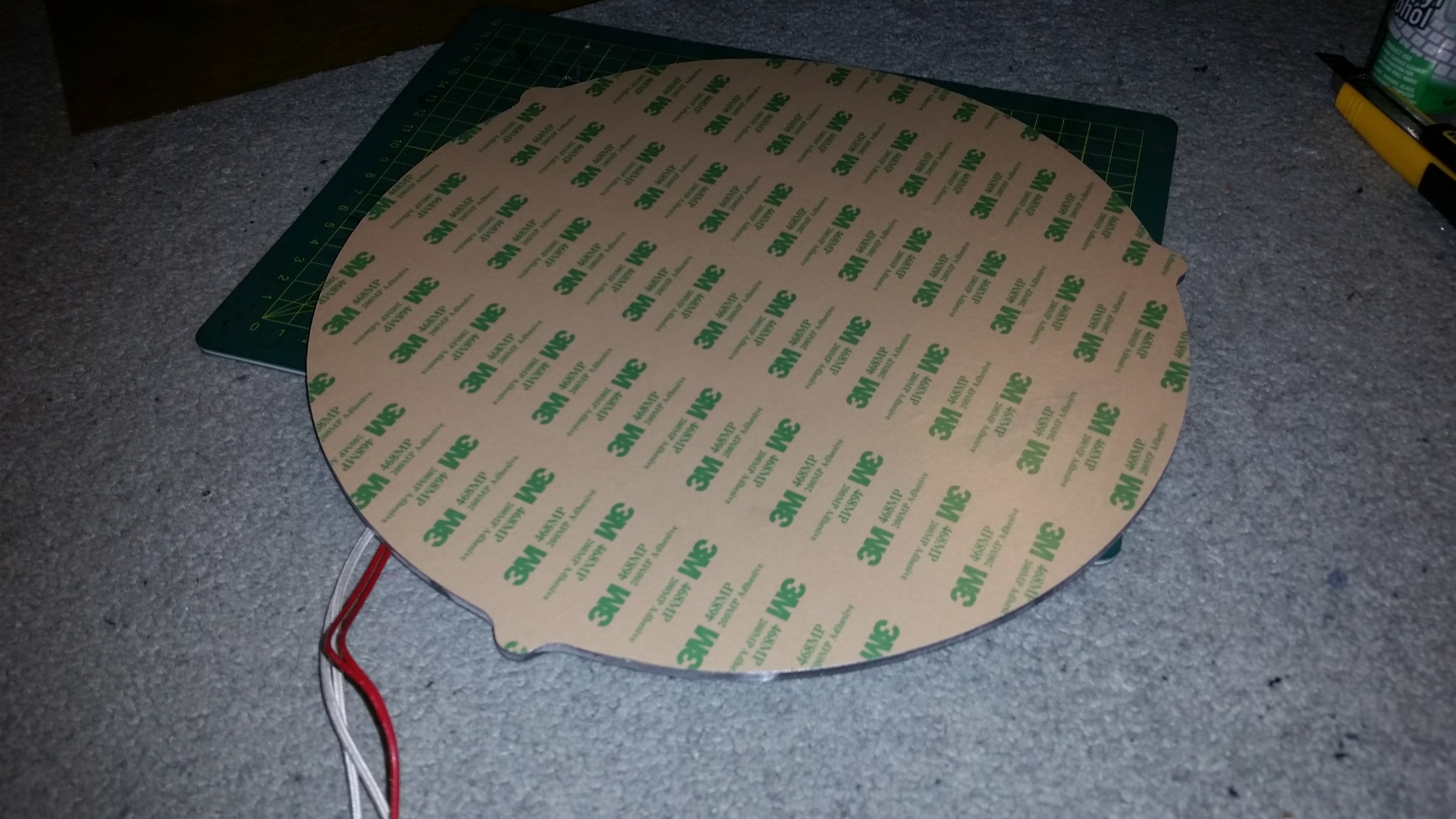
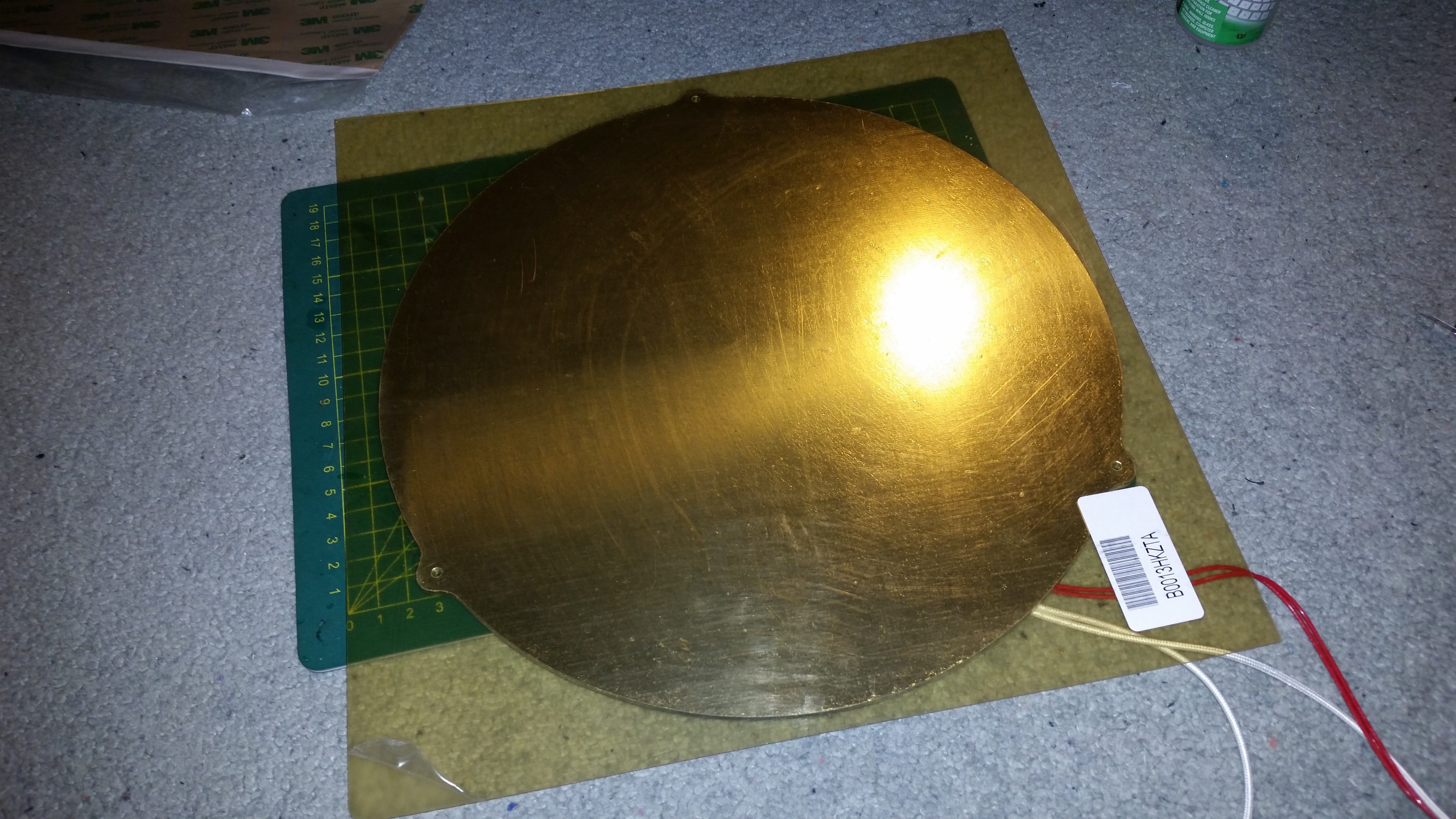
For the PEI surface, I bought some 0.03" x 12" x 12" sheets from Amazon. I also purchased some 12" x 12" 3M 468MP adhesive transfer tape. The tape was first applied to the aluminium.
![Transfer tape applied]()
Transfer tape applied
I then peeled off the backing from both the transfer tape and PEI sheet. The PEI sheet was rolled down onto the transfer tape. PEI sheets come with a matte surface finish on one side and a gloss finish on the other. I decided to go with the matte surface for printing on.
![Overhanging edges]()
Overhanging edges
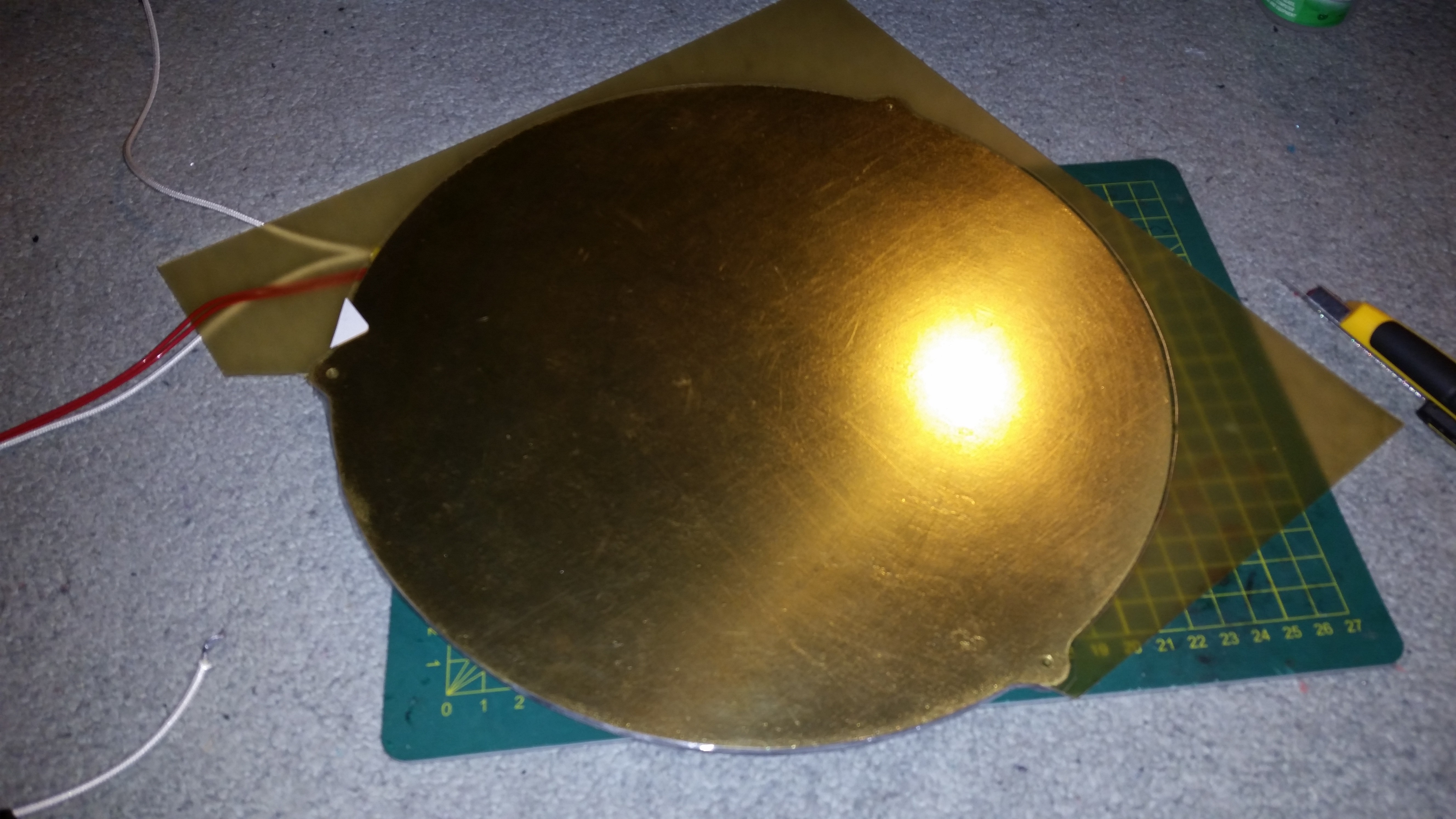
The bed was flipped over and I carefully scored the PEI using the aluminium edge as a guide. I used some small files and sandpaper to clean up the rough edges.
![One third done!]()
One third done!
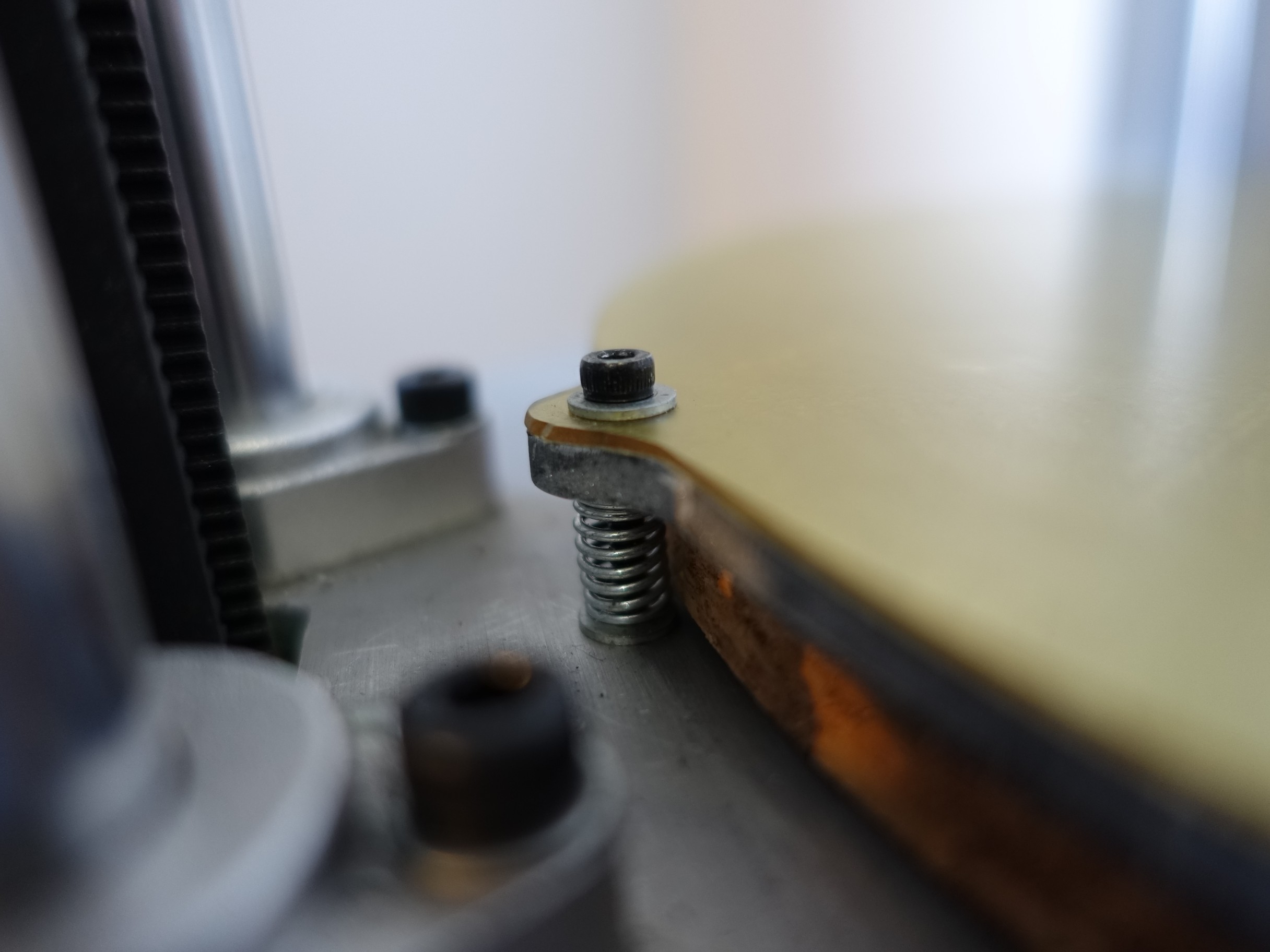
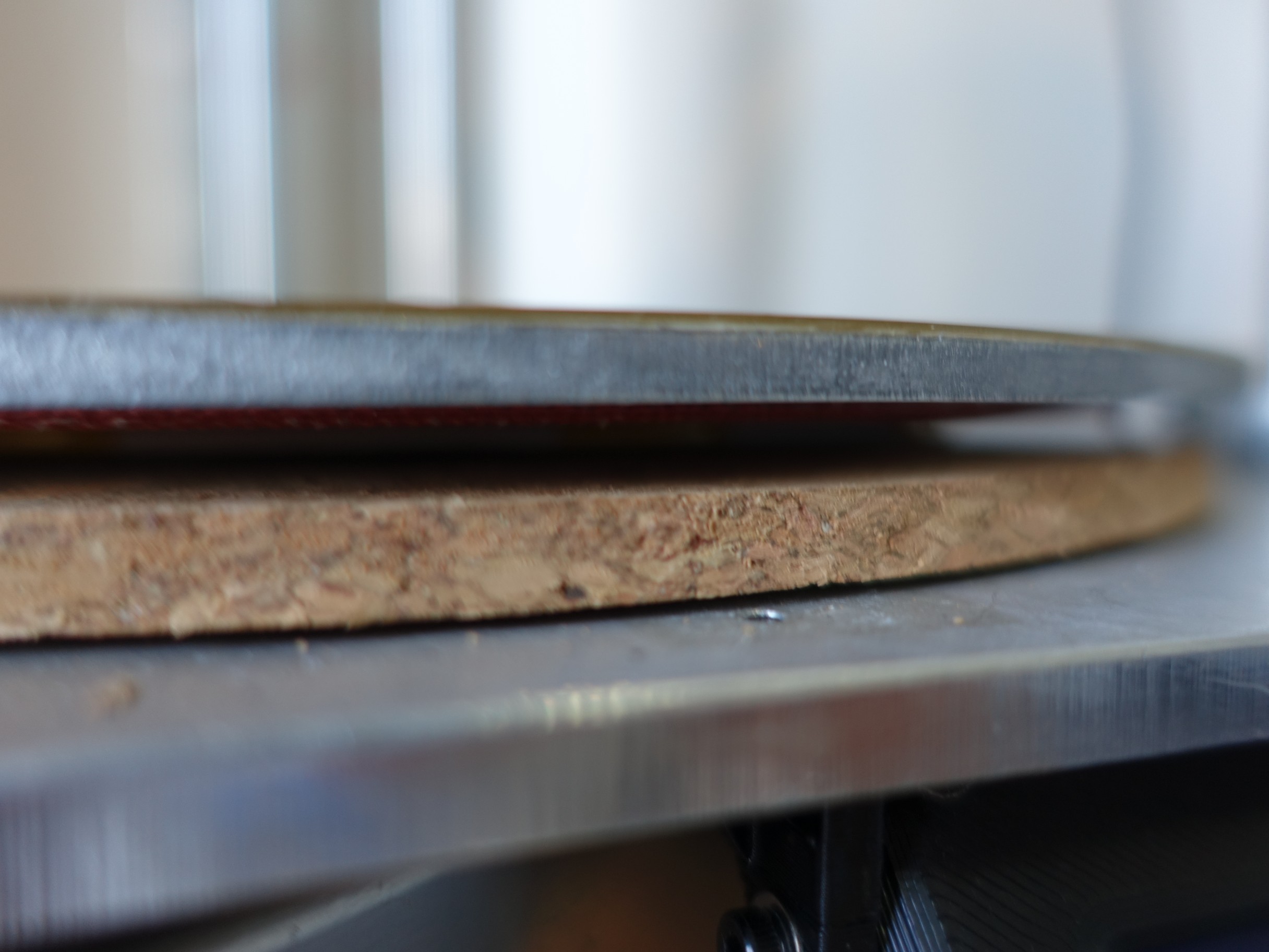
I reused the same 3mm bolts and springs from the old bed. A cork tile was cut to size and placed underneath for insulation.
![Spring mounted]()
Spring mounted
![Cork insulating tile]()
Cork insulating tile
The control board required no modification as the SSR is driven from the existing heated bed MOSFET. I had to lower the PWM frequency to 5Hz so as not to switch the SSR too frequently. This works fine with PID control as heating the bed is still a very slow process. After a PID tune, the bed now takes about 30 seconds to get from ambient temperature to 60°C (140°F) for printing PLA.
I initially had a lot of trouble getting PLA to stick. It was quite disheartening after all that effort. I did a lot of reading and tuning to try and get better adhesion but saw no improvement. Eventually, the solution was to print the first layer about 10°C degrees hotter than normal. Now I have no first layer adhesion issues. I use some spray on isopropyl alcohol to clean the bed every few prints.
I’m really happy how the new bed turned out. Its larger, more efficient and cleaner to use.
-
Blower Fan Cooling Tube
03/31/2017 at 12:29 • 0 commentsIn my never-ending quest to reduce weight on the end effector I tried to think of exactly what was necessary to haul around. The hot end fan couldn’t be removed for obvious reasons and the mechanics were pretty lean already. The only candidate was potentially removing the part cooling fan, but that would obviously reduce print quality. I thought that there must be a way to relocate the fan and deliver the air remotely. The air delivery would have to be low pressure, high volume to provide good cooling. I would need a fairly large diameter tube which would in turn be quite heavy. If the tube was too heavy it would negate the whole concept.
I had a eureka moment while at my local makerspace one day. Two of the guys there have Muscular Dystrophy and require ventilators to help breathe. I noticed they had lightweight, flexible tubes delivering the air to their face masks. This type of tube would be perfect! A few phone calls later I found myself at a CPAP machine distributor. For AUD$25 I got a 2m length of very light, strong and flexible tubing.
![This blows!]()
This blows!
![Heavy part at the top]()
Heavy part at the top
The concept worked! The blower fan was able to deliver a decent flow and cool well. It also meant that I didn’t have the weight of extra wiring going down the bowden tube. It was very important to get the tension in the tube correct along its length as it had the tendency to be quite springy and exert force on the bowden tube.
I used this setup for a while until I upgraded to magnetic ball joints. Even though the tube was very flexible it would still exert a twisting force on the end effector. Unfortunately, this caused the magnets to disconnect quite often so was abandoned.
-
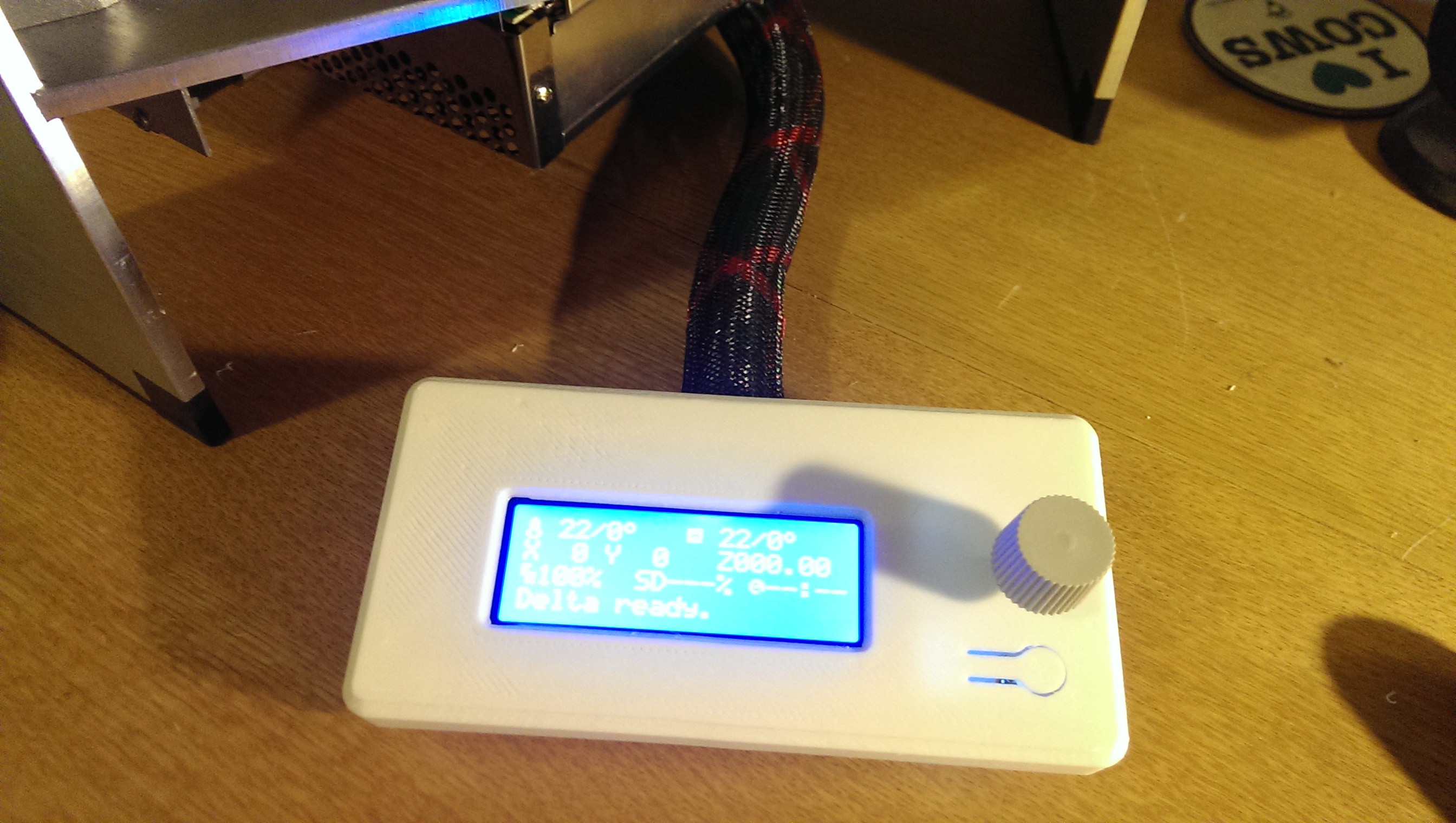
Retractable Screen
03/31/2017 at 12:29 • 0 commentsThe RAMPS board originally came with a ReprapDiscount 2004 Smart Controller. One of the early things that I printed was a nice case for it. I decided to not attach the panel to the printer because I couldn’t find somewhere to mount it that I was happy with. I couldn’t elegantly fit it within the footprint of the printer. I used some mesh cable wrap to protect the two ribbon cables. When transporting, I would disconnect the plugs on the back of the panel and put it in my toolbox.
![Temporary knob]()
Temporary knob
I purchased a GLCD along with the new MKS SBASE control board. This screen is taller but not as long as the Reprap Discount Smart Controller. With a bit of planning, I found a way to keep the screen within the footprint of the printer while making it permanently attached and usable. The screen would fit in a small area between the back of the power supply and underneath the Y tower. I wanted the screen to be flush underneath the printer for storage/transport but pop out when required. I prototyped a few retraction mechanisms but none of them worked due to the limited space behind the screen. I then realised I had seen the perfect mechanism on a kitchen cupboard door at my parents house.
![Mini Latch]()
Mini Latch
The mini latch had a “press to open, press to close” action that would be perfect. I just had to print a way of attaching it to the printer with such limited space. I adapted a GLCD screen case from Thingiverse and attached the mini latch to the side.
Once it was all in place the back of the SD card only just clears the power supply - but it works great!
-
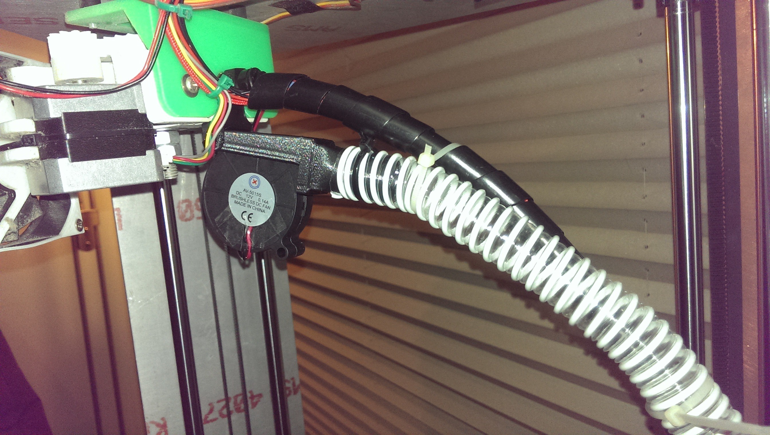
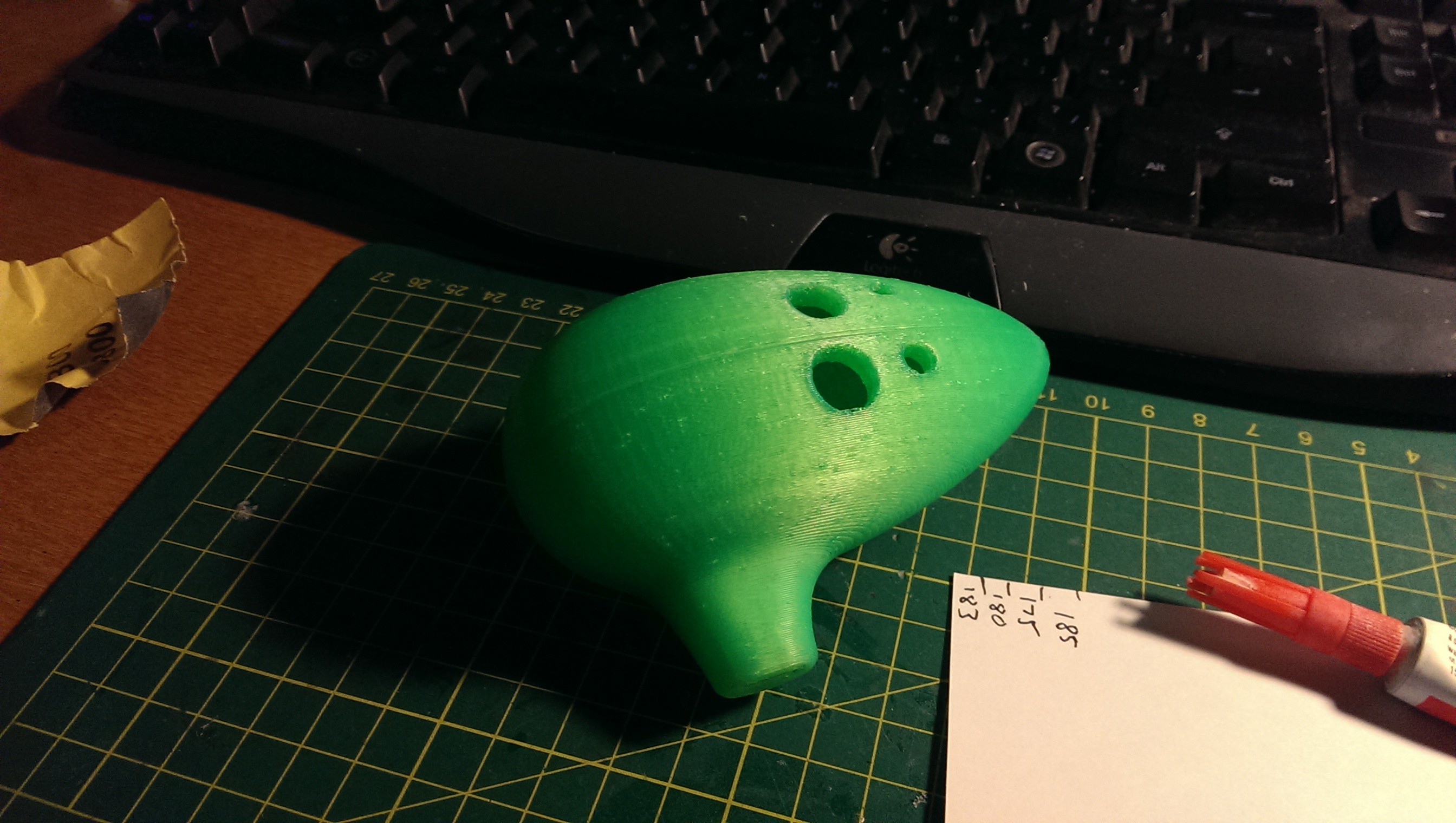
Controller Upgrade
03/31/2017 at 12:28 • 0 commentsIt was a few months after I started printing that I was really getting the slicer settings dialled in. I had learned so much about how each parameter affects others. This meant that I could start pushing the speeds up to get faster prints. I started to notice that there were tiny little “bullets” appearing on the surface of my prints. At first, I thought they were where a layer change was occurring but it turns out the printer was pausing for the tiniest moment.
![Ocarina with bullets]()
Ocarina with bullets
After a bit of research and experimenting with the Marlin configuration file, I realised that the Arduino MEGA couldn’t keep up with the high speeds. There were a few options to reduce the computational load but none of them had a huge effect. I was also interested in auto leveling (tramming) which Marlin didn’t support well for delta printers at the time (Late 2014).
Mid 2016, after getting back from a year abroad, I started researching 32-bit ARM-based boards. There were a few on the market that were quite mature. One that stood out the most was the Smoothieboard. It had all of the features that I needed and I’d read some great reviews of the Smoothieware firmware to go with it. Unfortunately, the Smoothieboard was way out of my budget. It was then that I discovered a few other boards that were listed as “Smoothieware compatible”. I did some more research before settling on the MKS SBASE. It’s a Smoothieware compatible clone from Shenzhen that costs around USD$50 - about five times cheaper. There is quite a bit of negative feedback on supporting the SBASE as the manufacturer won’t open-source their design, effectively ripping off the open-source community. I still feel pretty guilty about the purchase.
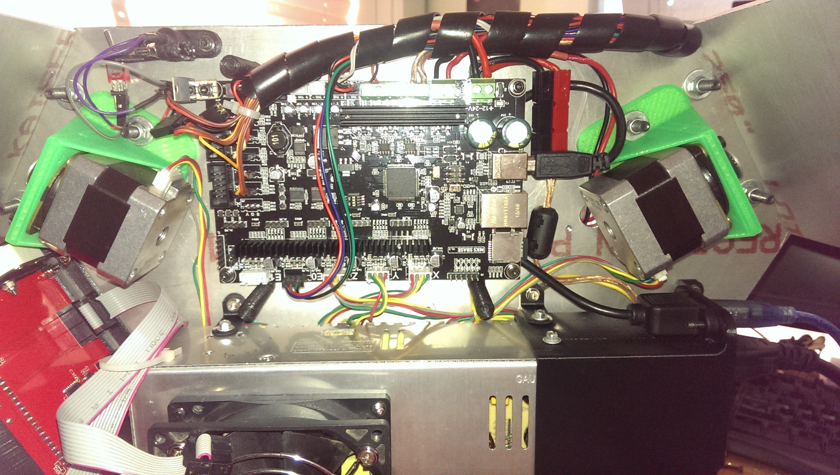
The transplant went fairly straightforward. I printed a custom bracket to hold a nice big quiet fan for cooling. I also added some plastic spiral wrap to neaten up the wiring.
![Just fits]()
Just fits
It was immediately noticeable just how smooth the new board and firmware was. I never saw the bullets again.
-
Power Supply Issues
03/31/2017 at 12:27 • 1 commentI’ve blown up a few printer control boards throughout this project. It turns out they were all caused by one tiny little short on the corner of my heated bed. This took quite some time to find.
I first discovered the issue when I had the printer plugged into my PC. At the time, I was trying to print direct from Repetier-Host rather than the SD card. I started printing and a short time later the printer froze. As I moved over to check it, I brushed past the USB cable and discovered that it was piping hot! I quickly unplugged it and discovered that I had well and truly let the smoke out of the Arduno MEGA.
I immediately suspected that my cheap imported power supply was to blame. It was supposed to have a floating ground so I thought that its negative would sit at the same potential as earth. I’d read somewhere that some cheap power supplies don’t have a floating ground and this can cause dangerous ground loops.
I replaced the Arduino and checked all of my wiring for shorts. I couldn’t find anything that would have caused it. Measuring the voltage across the heated bed and hot end MOSFETs was very confusing because I didn’t realise they were sinking current. I mistook it that the power supply was providing 12V at “ground” and 24V at “12V”, giving a 0 to 12V range.
I decided not to use the USB cable anymore and the problem disappeared. If I ever needed to flash the firmware I used my laptop that was not connected to anything else. Everything went fine.
At a much later stage, after a trip to Shenzhen, I installed a new power supply in the hope that it would not suffer from the same ailment. I got it all wired up and plugged into the computer. To much celebration, it didn’t fry the Arduino MEGA. Success!
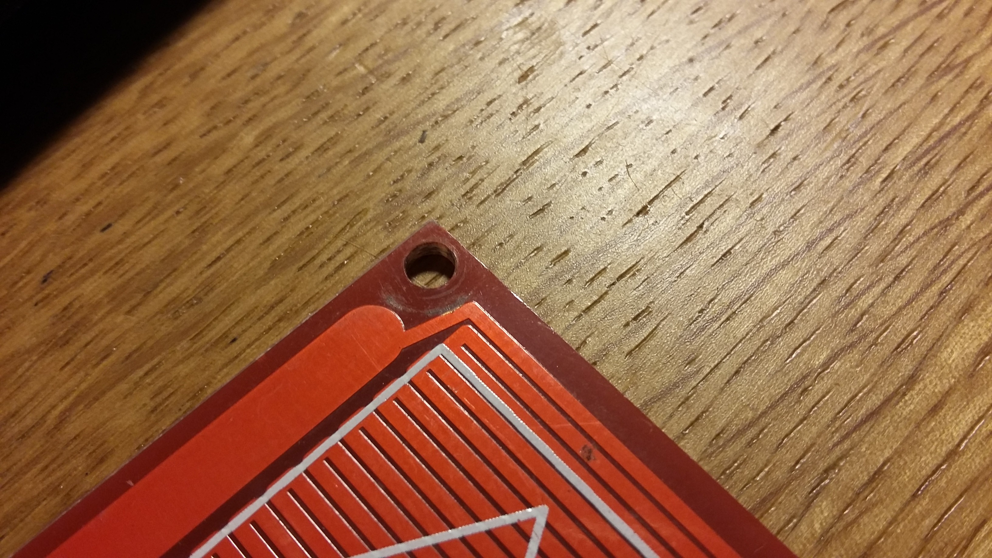
Not long after that I upgraded the RAMPS/Arduino control board to a Smoothieware-based MKS SBASE. I was confident that I would not have any issues and the transplant went smoothly. One day, before printing, I plugged in the USB cable to update the configuration file… and let the smoke out! I couldn’t understand why the problem had re-emerged after so long AND I had replaced the power supply. I decided to do some tests since the board was fried anyway. It seemed that the problem only occurred while printing. This was the first clue. I did some probing of the heated bed with my multimeter and found that there was a dead short between the two wires! I then discovered this:
![The culprit!]()
The culprit!
The small washer that I had used for the spring mounts had cut through the trace and was shorting out. I suspect that while the printer USB cable was disconnected, the whole ground potential of the printer was much higher than earth but everything would be fine. When the USB cable was connected, it would short the 30 amp power supply to ground through the braided shielding on the cable. This in turn would blow up the USB chip and/or the main processor. I’m lucky that my PC USB ports were not fried as well!
After isolating the cause, and purchasing a replacement MKS SBASE, the problem never emerged again and I don’t have to worry about the USB cable anymore.
-
Carry Handle Upgrade
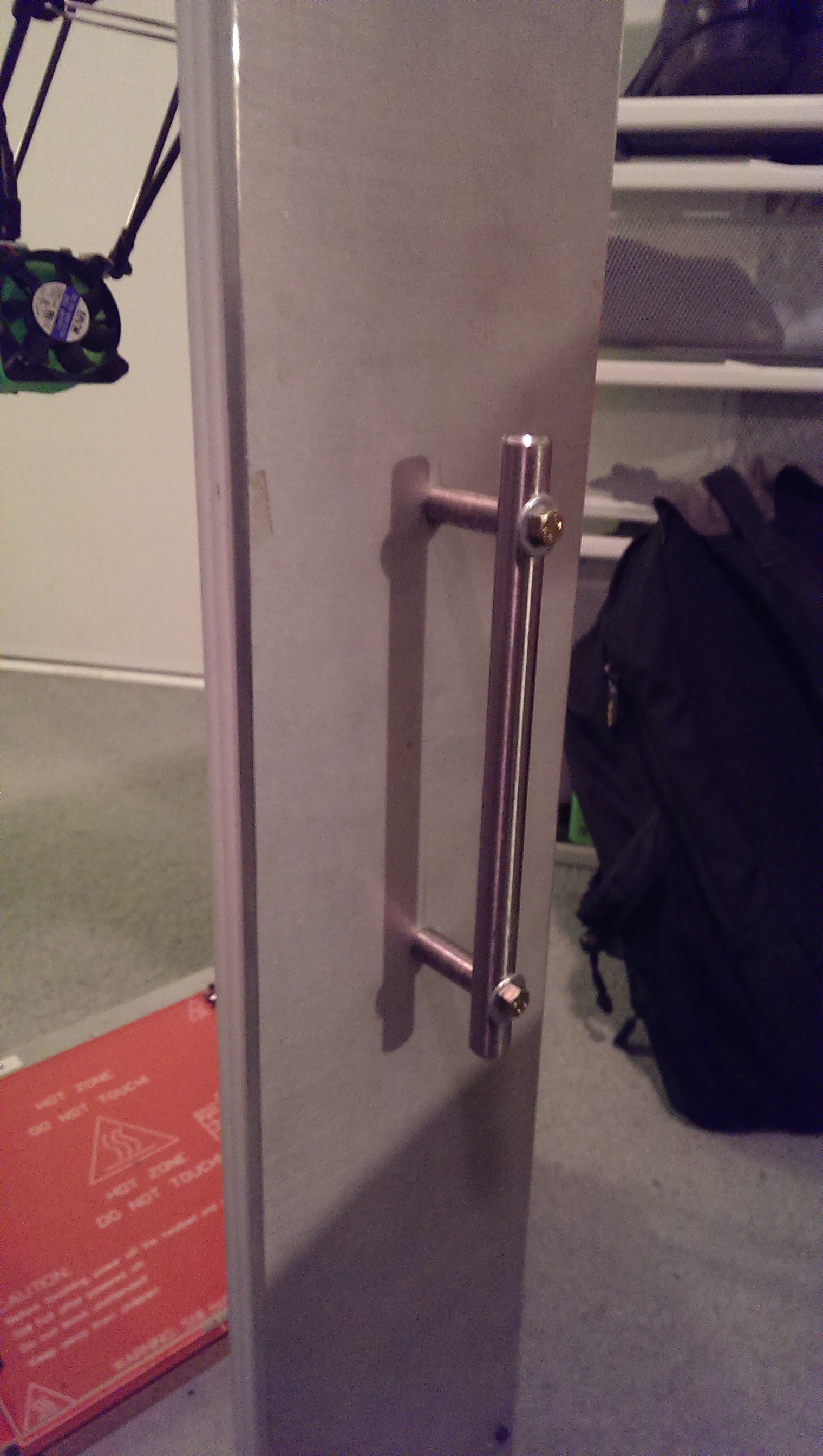
02/01/2017 at 10:14 • 0 commentsWeighing in at around 17kg (37.5lbs), this printer is very heavy. It is also almost 900mm (35.4in) tall which is cumbersome to carry. I modified a cupboard handle and attached it to the rear tower of the printer with some high tensile bolts. It goes against one of my design goals of having all parts of the printer inside the triangular footprint. The convenience of having a carry handle outweighs that design goal by far.
![]()
Strong enough