-
Slider Upgrade
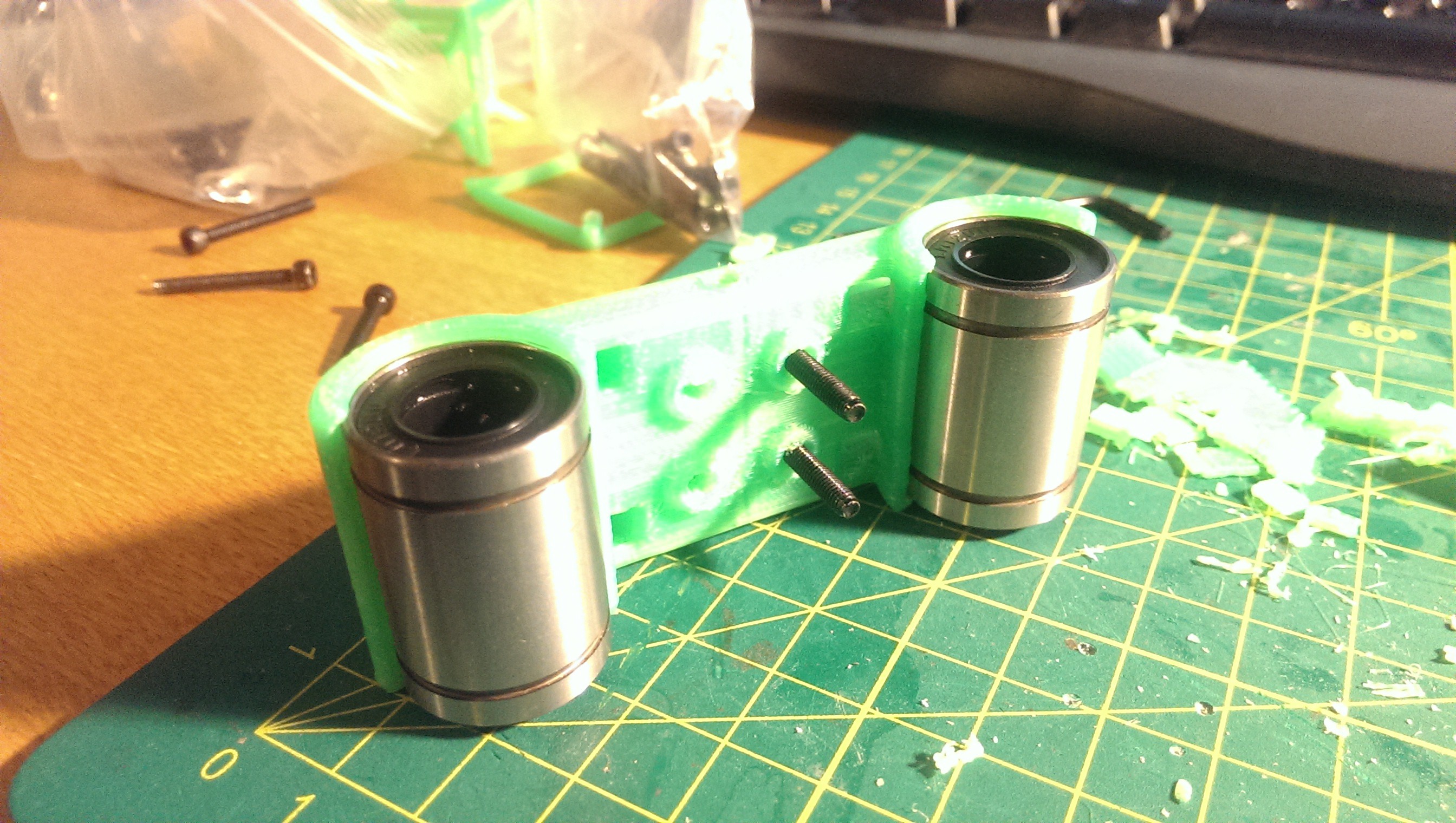
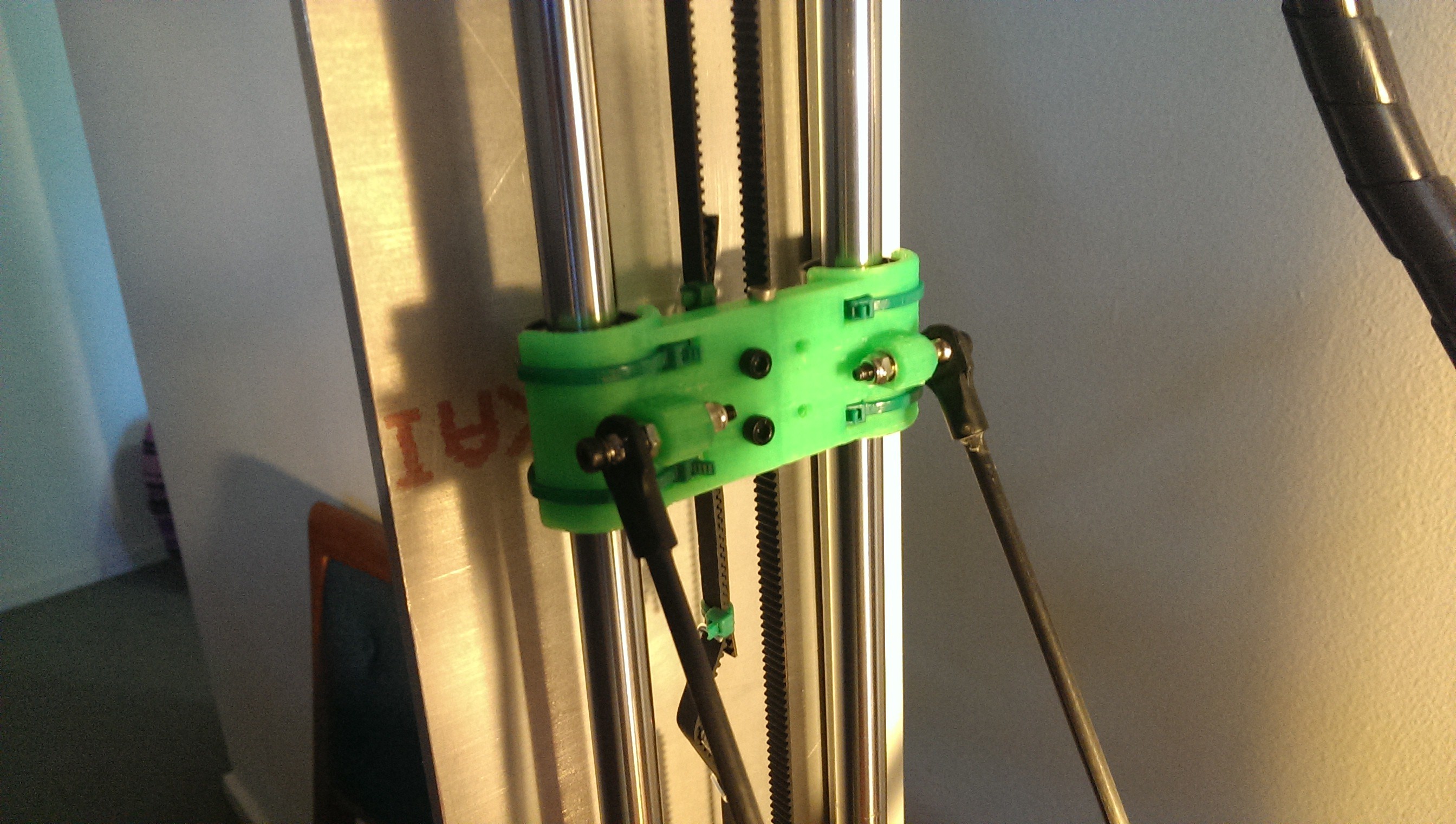
02/01/2017 at 10:11 • 0 commentsThe original vertical sliders were laser-cut MDF. The design worked well. One of my priorities was to replace them with custom printed parts. I ensured that the critical dimensions were exactly the same so that they would be a drop-in replacement. I re-used the same LM12UU linear bearings. Some of the improvements include printing a small lip around the top and bottom of the bearings so that they could not slide out, and the inclusion of a small recess for the endstop magnet to sit in.
![Slider V3]()
Slider V3
![Slider V3 installed]()
Slider V3 installed
-
Vibration, Resonance & Sound
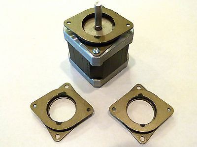
02/01/2017 at 10:08 • 0 commentsDue to the rigidity and material of the frame it was very good at transferring sound and resonating. Initially, the motor brackets rigidly mounted all stepper motors to the frame. Any vibration or high pitch noise would directly enter the frame and seemed to amplify. I found some fantastic “Astrosyn” vulcanised rubber motor mounts online and, after reading some great reviews, bought a set.
![Astrosyn Dampners]()
Astrosyn Dampners
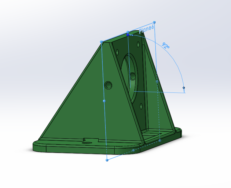
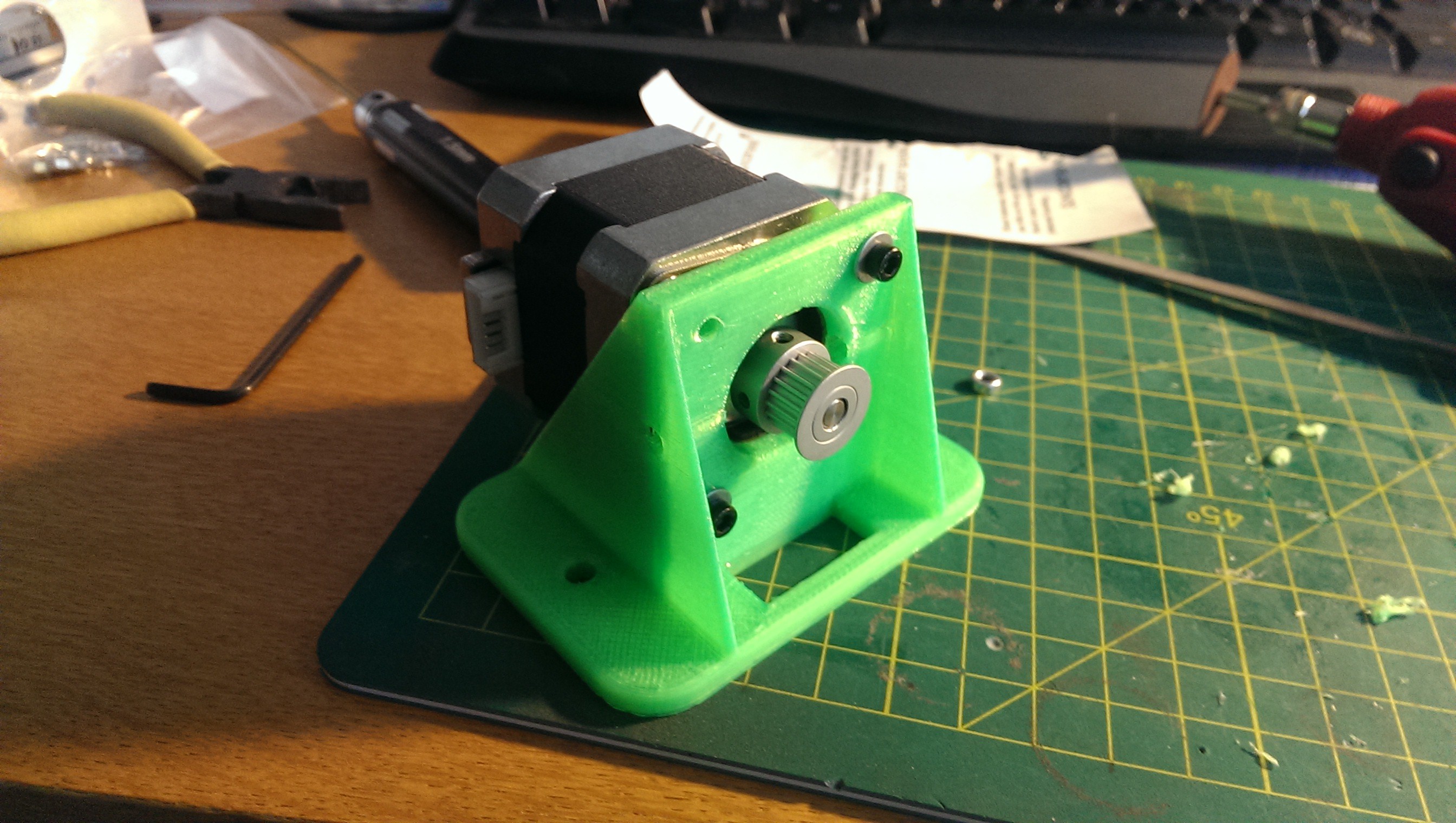
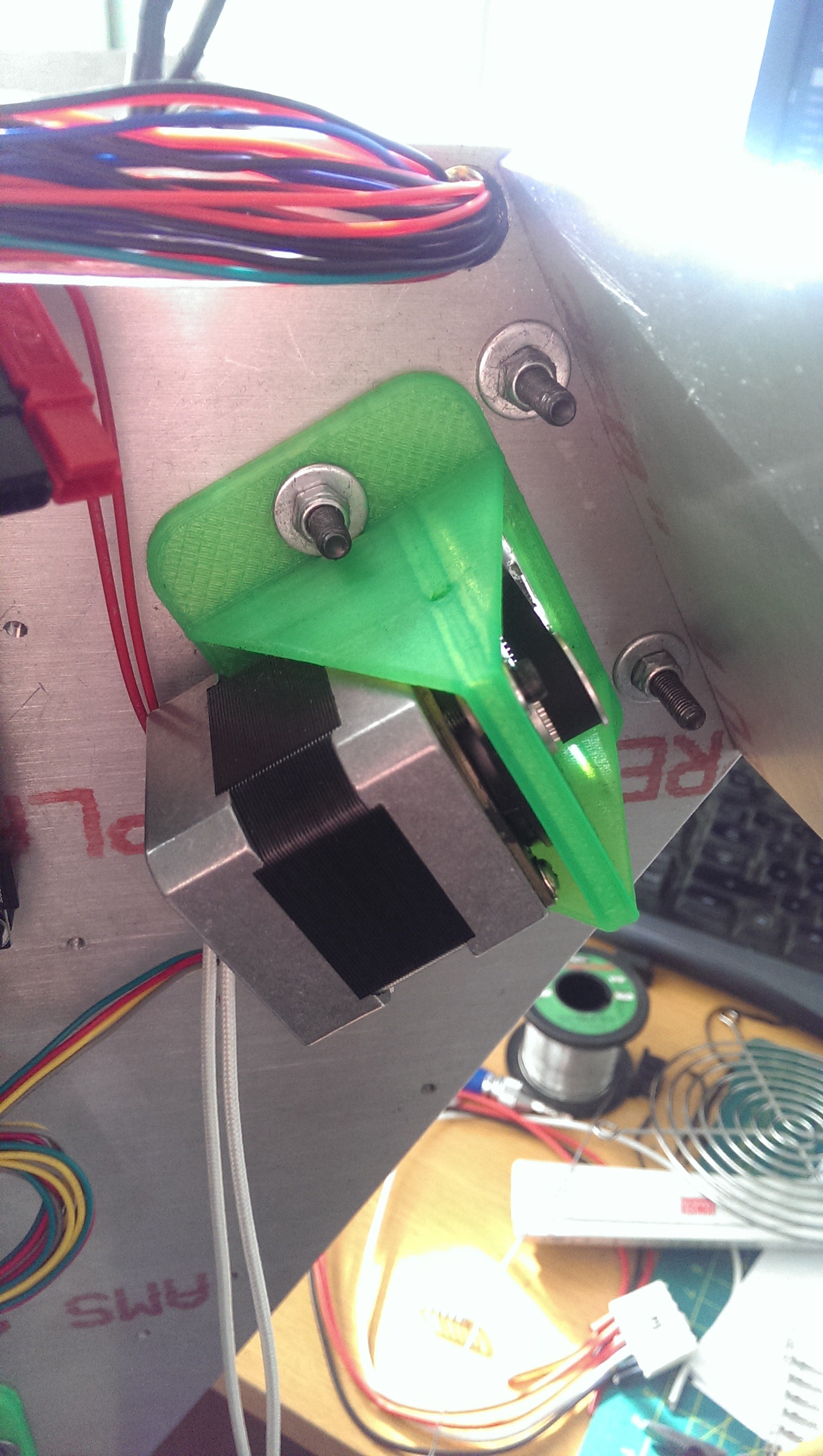
Due to clearance issues, I had to print some new stepper motor brackets. This ensured that the back end of the stepper motor would not be touching the bottom plate of the frame. I noticed that there was a bit of flex in the rubber vibration dampners so designed a slight 2° angle into the flange part of the bracket.
![A slight angle]()
A slight angle
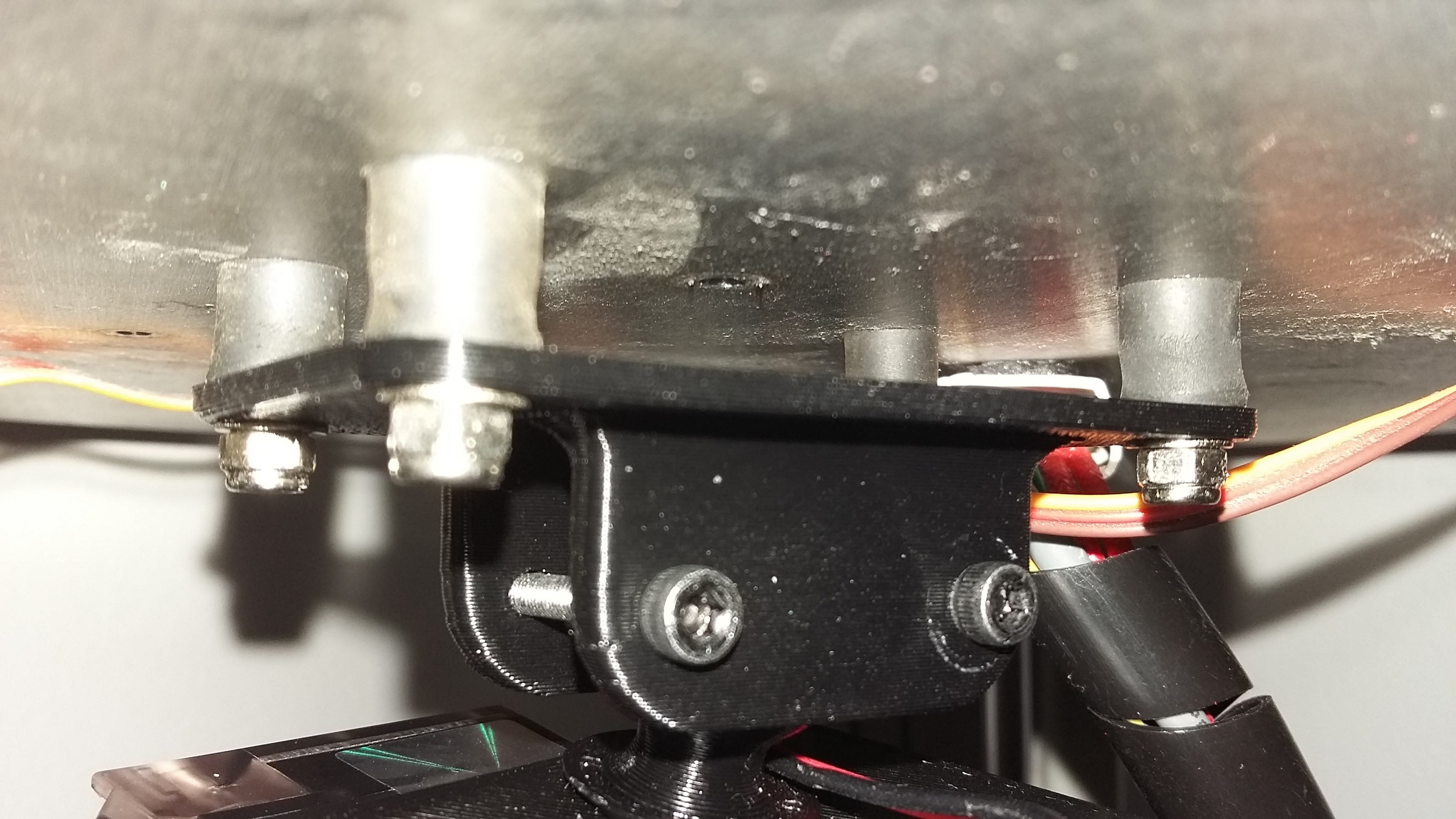
This allowed the motor shaft to remain horizontal and prevent the belt from bunching up at the far end of the pulley. I added a small hole in each side of the bracket to allow the pulley grub screw to be accessed easily. Without this hole, I would have to dismantle the whole thing to adjust the pulley position on the shaft. I also made the bracket use the same bolt from the linear rail clamp and it turned out quite neat.
![Fits well]()
Fits well
![Neat!]()
Neat!
The extruder was probably the noisiest due to the rapid changes in direction. I found some M3 rubber standoffs to use for isolating the extruder motor. These cut out most of the resonating noise.
![Future extruder mount]()
Extruder mount (future)
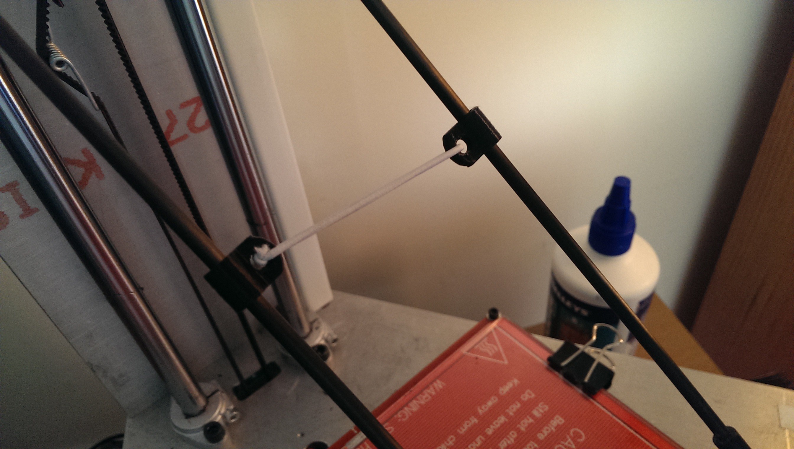
A common problem with using ball ends is that they have a tiny amount of play. This can adversely affect print quality, especially at higher speeds. Most people use rubber bands between the rod pairs to keep some tension on the balls. I adopted this method as well. My rubber bands started to perish so I bought some elastic and printed some tiny clips.
![Arm tensioners]()
Arm tensioners
-
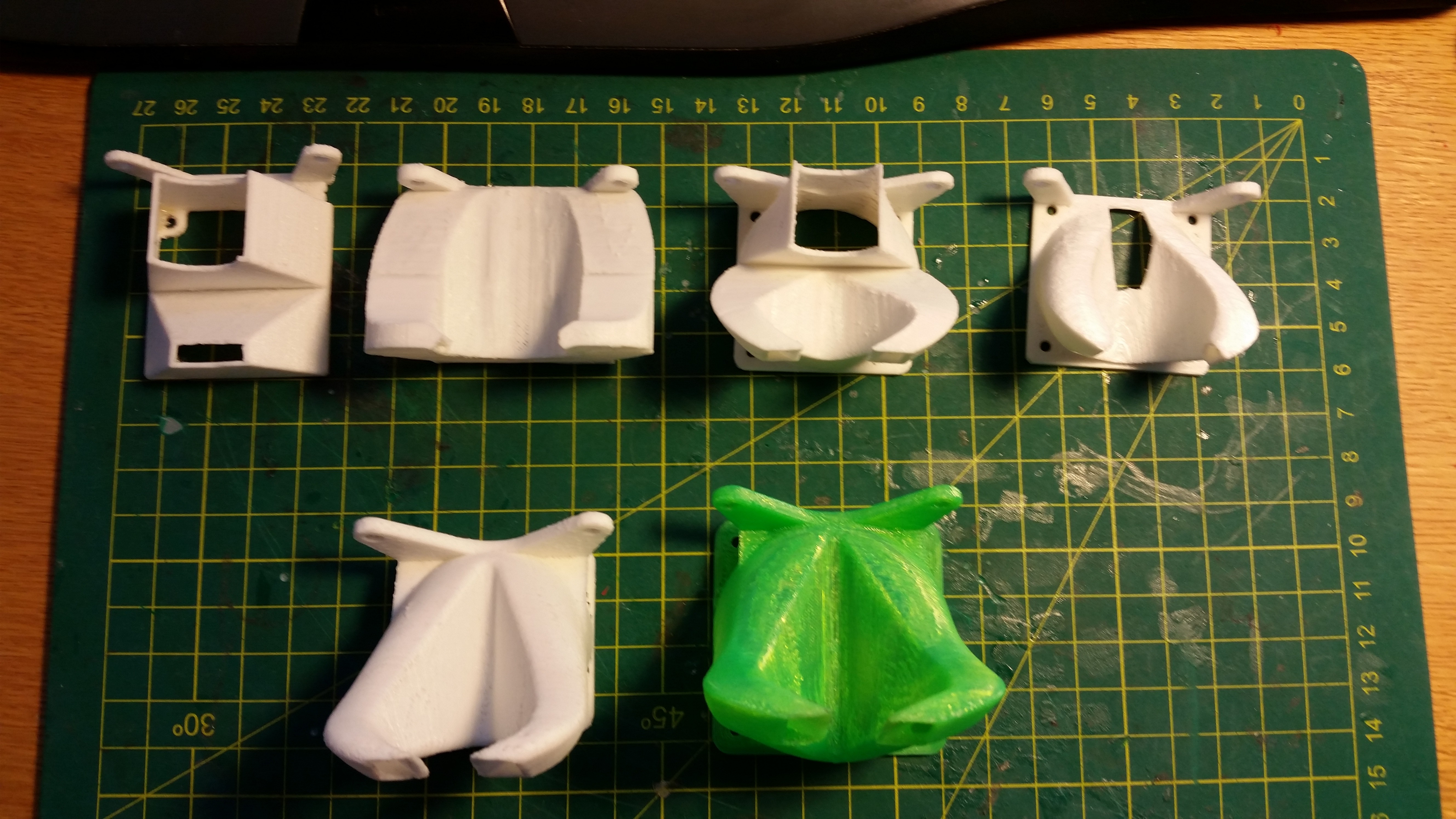
Fan Duct Evolution
02/01/2017 at 09:59 • 0 commentsInitially I cable-tied a 40mm fan to the end effector. It wasn’t cooling very well so I designed a fan duct to redirect the airflow. The first version improved the overhang performance but only from one side. Edges still curled on the opposite side to the duct. I revised the design to split the airflow in two and redirect it to either side. This helped to stop the uneven curling.
![Original fan mounting]()
Original fan mounting
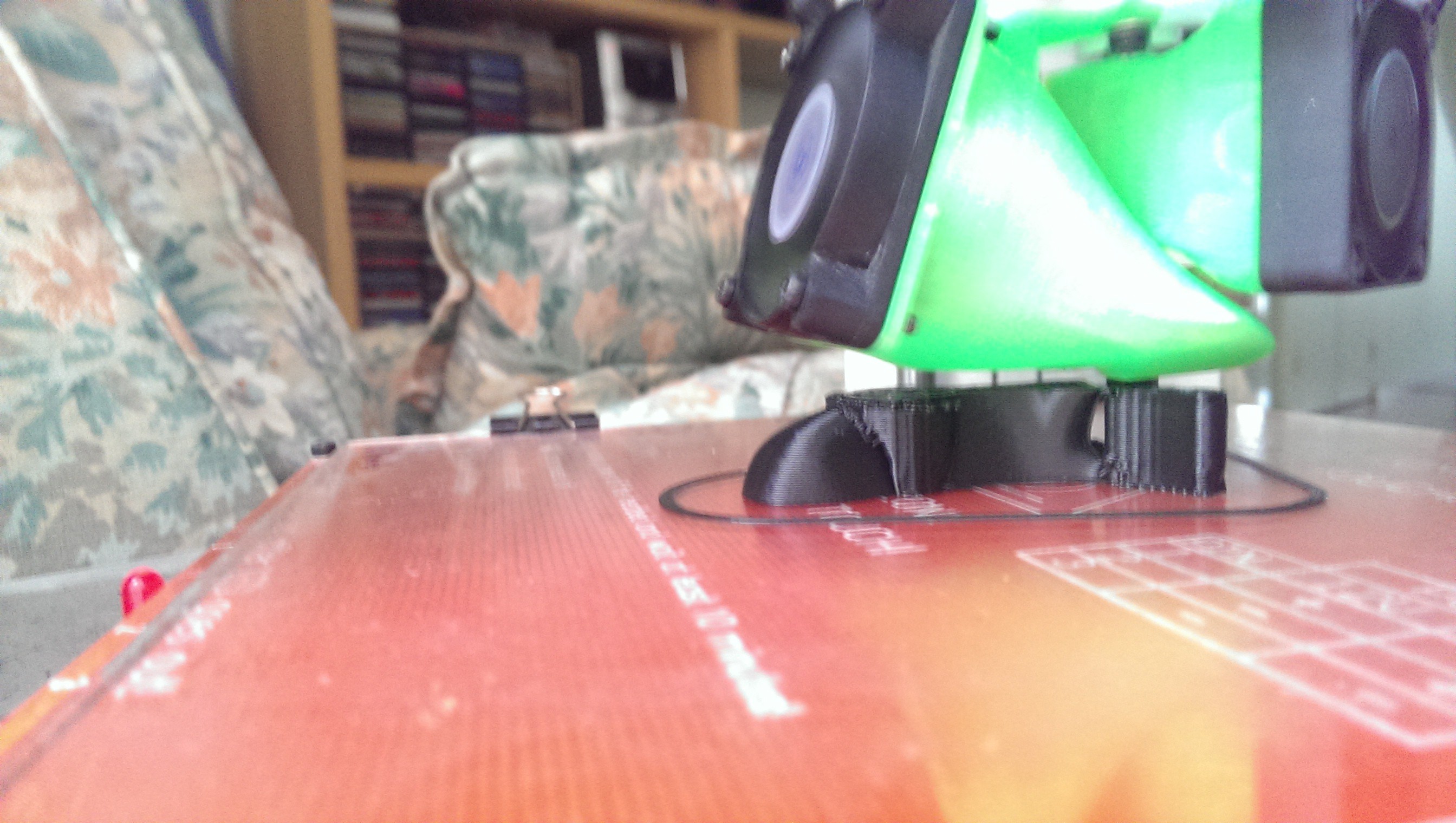
After I upgraded to the E3D V6 Hotend I used its included 30mm fan to cool the heatbreak fins. I then modified the duct to accommodate a larger, quieter 50mm fan sourced from an old 486 heat sink. The E3D fan was then upgraded to a larger 40mm fan on a printed adapter.
The heatbreak fan was tied to an always-on 12V supply and the larger cooling fan was connected to a spare MOSFET for dynamic speed control. Cooling worked well and produced excellent overhangs.
![Fan duct generations]()
Fan duct generations
![Cooling fan and heatbreak fan]()
Cooling fan and heatbreak fan
-
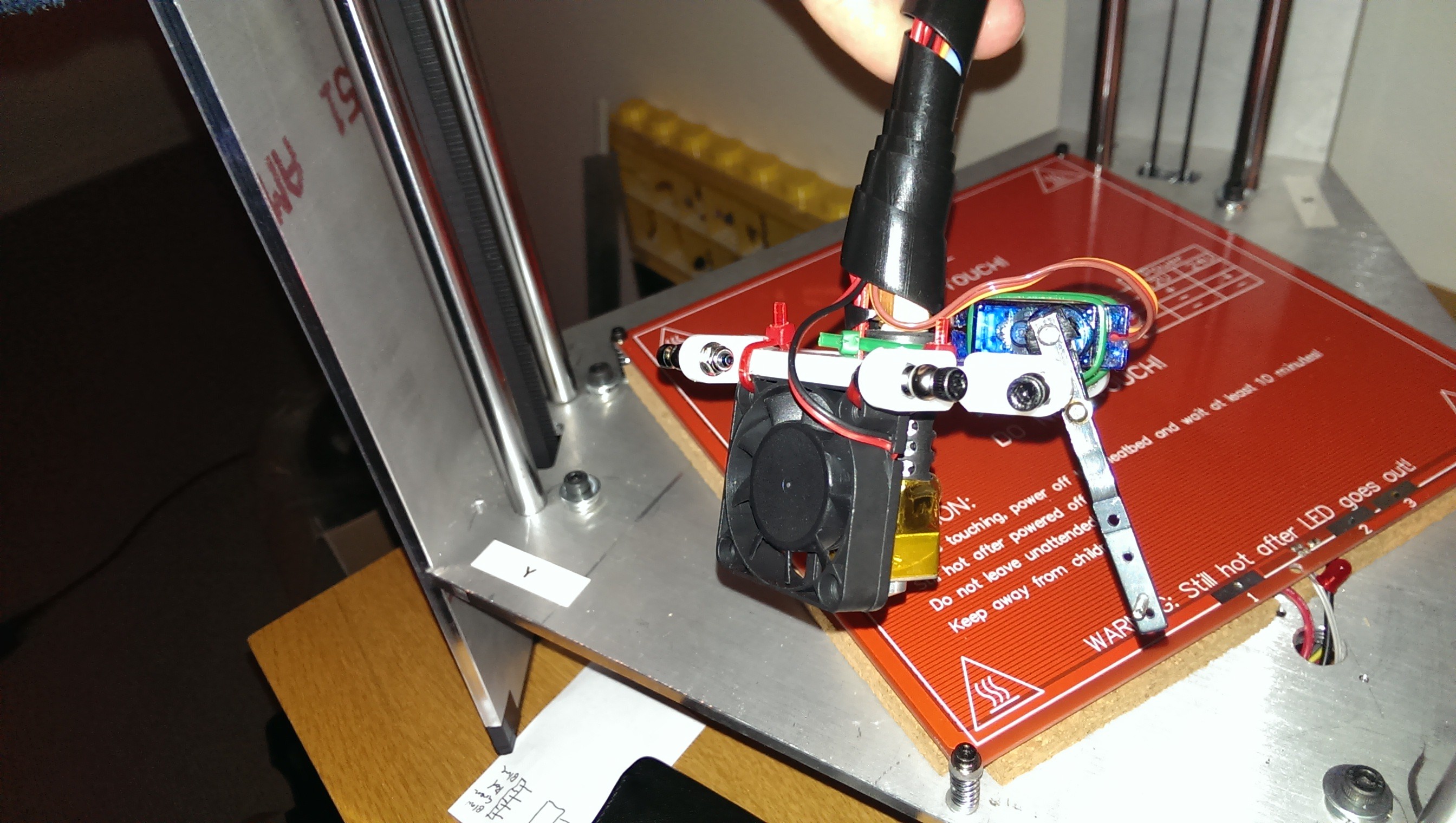
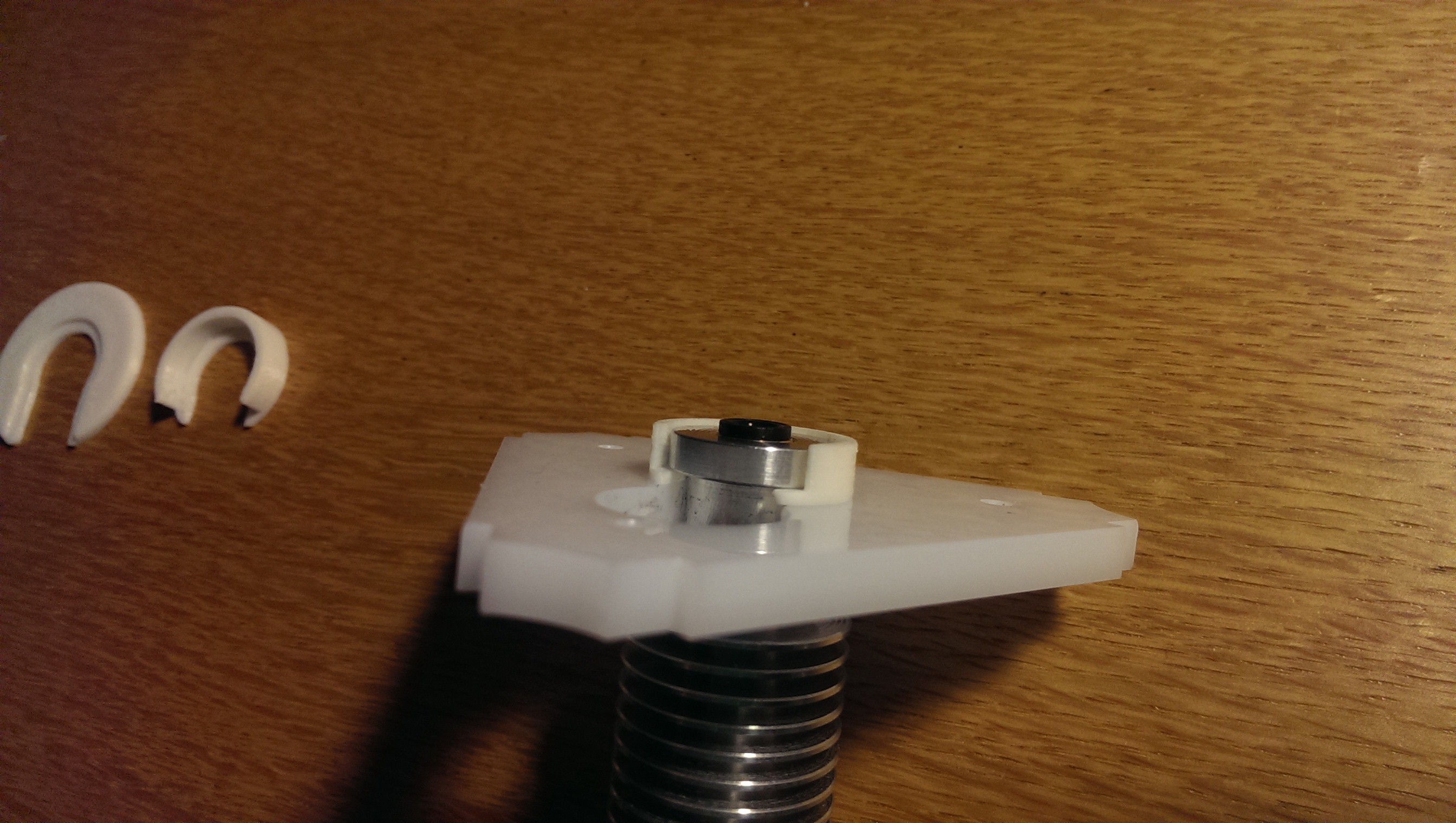
Hot End Upgrade
02/01/2017 at 09:49 • 0 commentsI started out with a cheap clone J-Head hotend running 3mm filament. Once I started tuning I was having difficulty with consistent flow rates and temperature. I also had occasional jams. I’d read amazing reviews of the E3D V6 hotend so ended up purchasing one. Supposedly it would drop straight into the grove mount in my end effector. It turns out that the J-Head required a 5mm thick groove whereas the E3D V6 needed a 6mm thick groove. This was quickly solved with a printed washer-clip.
![Washer clip thing]()
Washer clip thing
The rest of the upgrade was fairly straightforward. I had to reprint the fan duct. Luckily I had designed it with a somewhat parametric fan size so it was easy to scale.
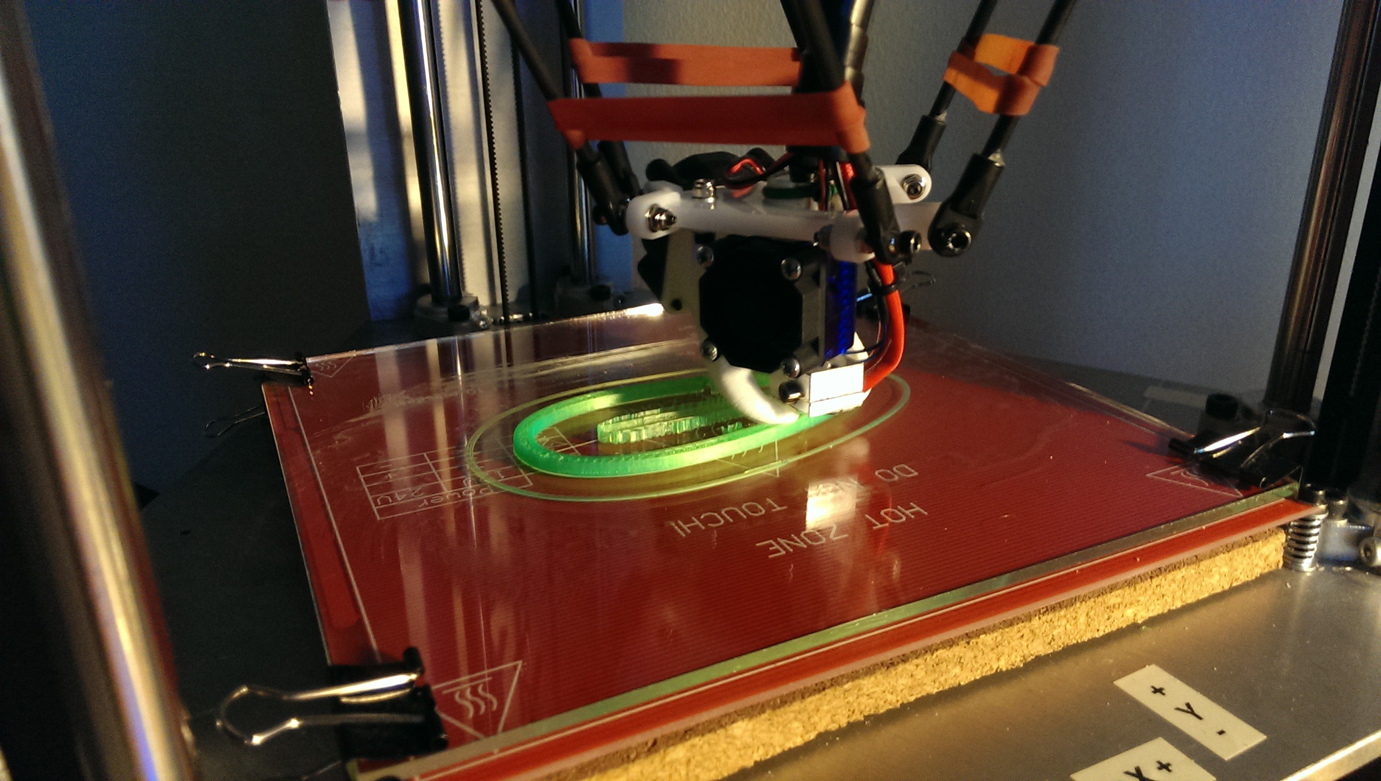
![Printing an ocarina half with the new E3D V6]()
Printing an ocarina half with the new E3D V6
The Greg’s Hinged Extruder was designed for both 1.75mm and 3mm filament so the only thing required at the cold end was to swap the Bowden push fitting for a smaller one. -
Power Supply & Cover
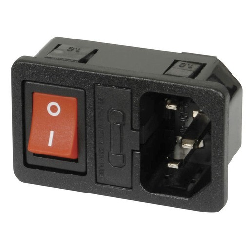
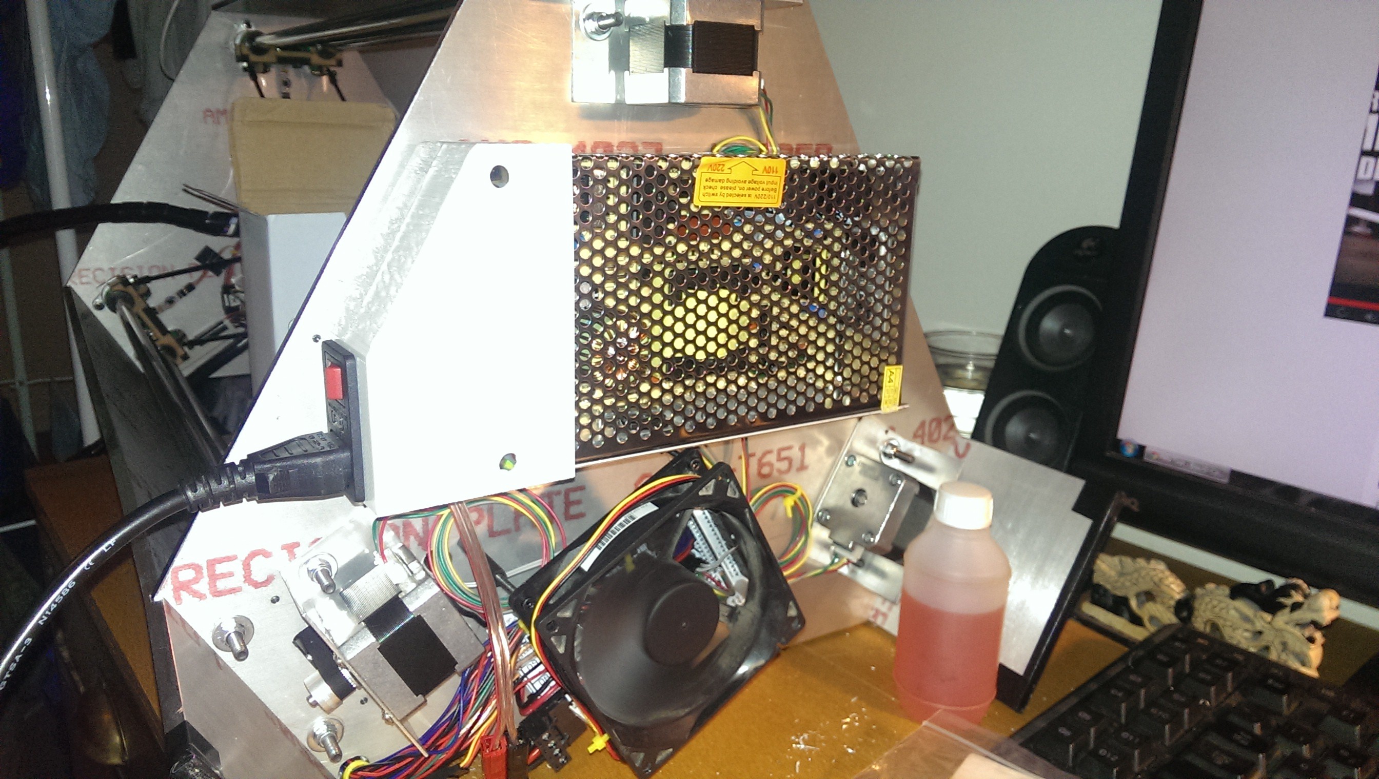
02/01/2017 at 09:45 • 0 commentsI initially powered the printer from my 12V 30A supply that normally charges my LiPo batteries. I wanted to wait until the printer was producing decent quality prints before starting with a few printed upgrades. I also didn’t want to start using the cage 12V power supply without having an enclosure to contain the mains wiring. I found a suitable little fused IEC13 socket at Jaycar. I wanted to be able to disconnect the power cord for ease of transport. I’ve always found it to be a pain to loosely wrap a cord around an appliance when moving it around.
![IEC socket with integrated fuse]()
IEC socket with integrated fuse
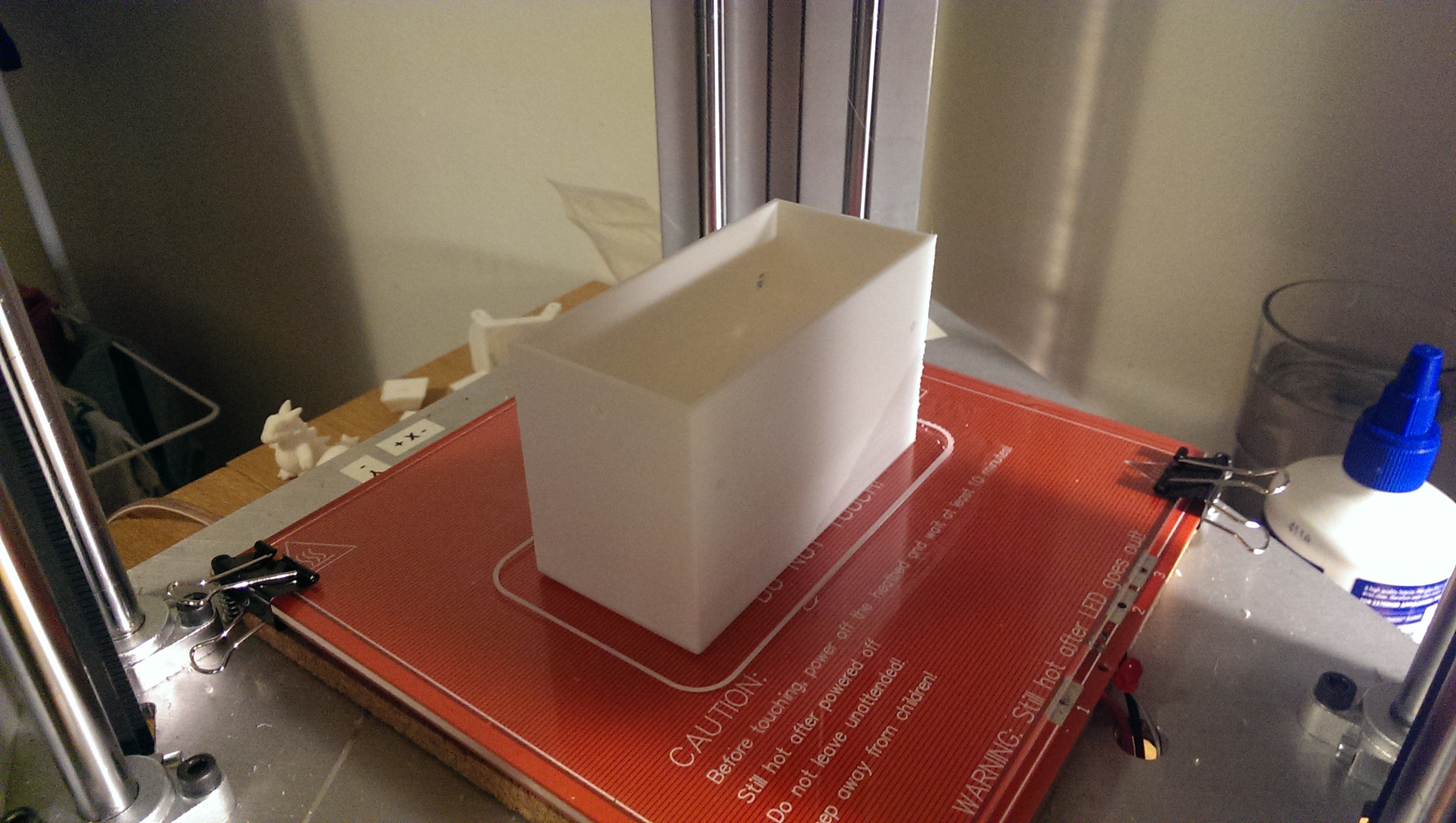
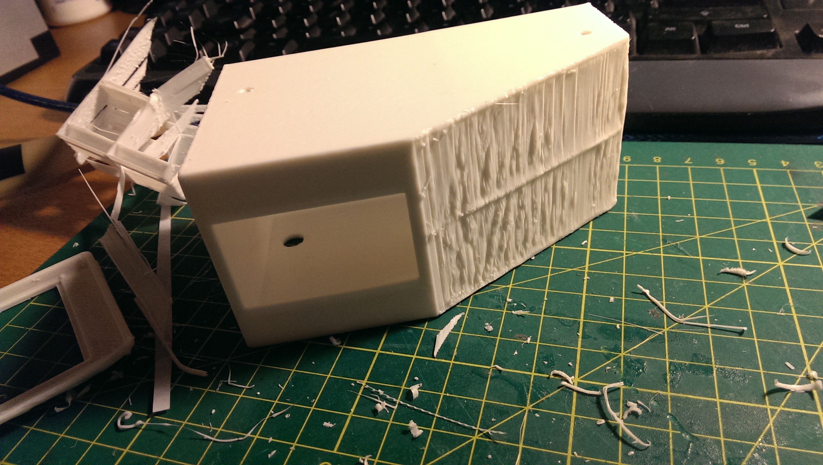
The overhang was pretty steep so I added some support walls. I then cut them away afterwards. The overhang finish was average but served its purpose. I was still dialling in the settings at this stage.
![One of the first big prints]()
One of the first big prints
![Steep overhangs]()
Steep overhangs
![Made to fit!]()
Made to fit!
-
Filament Holder
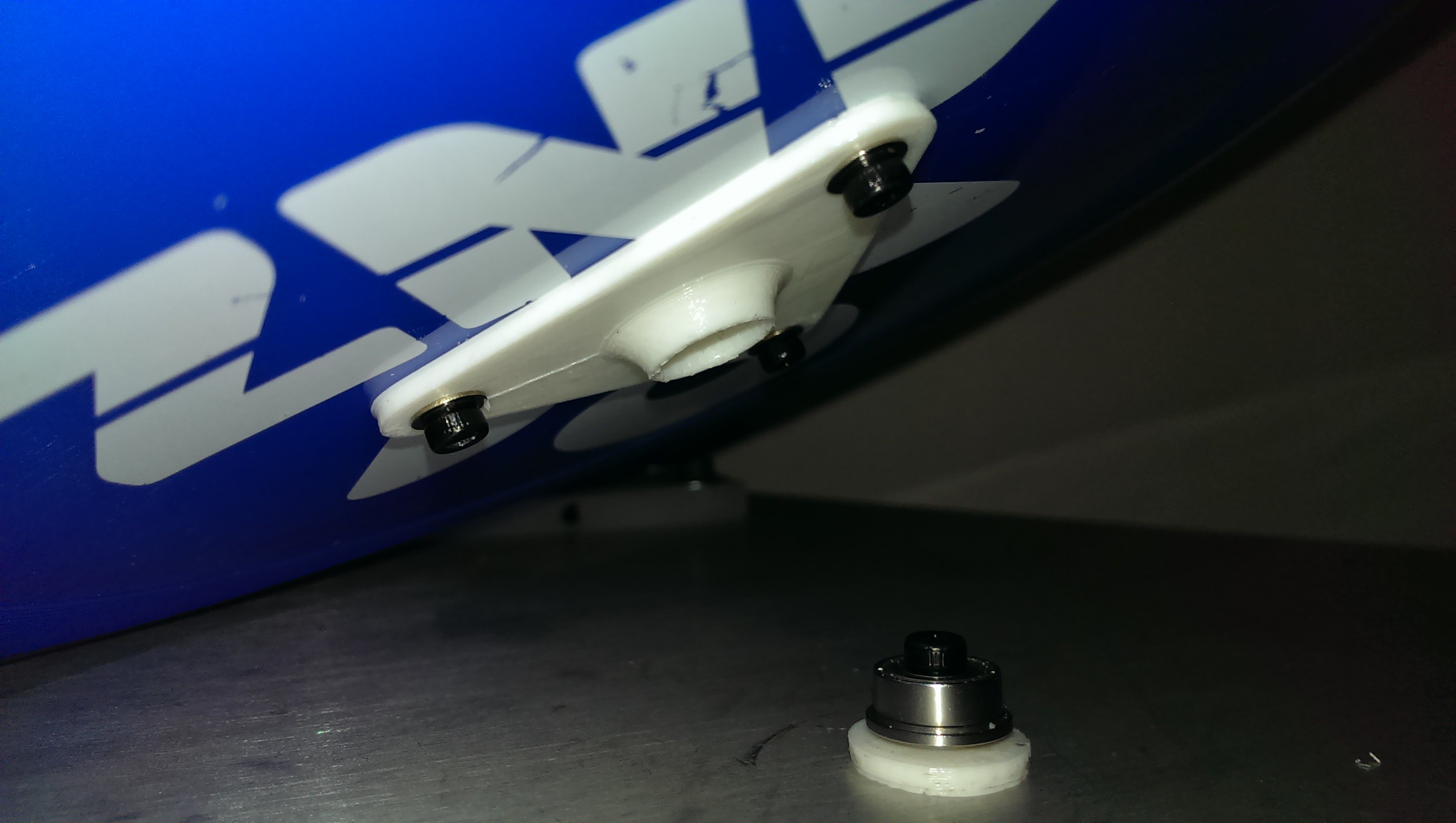
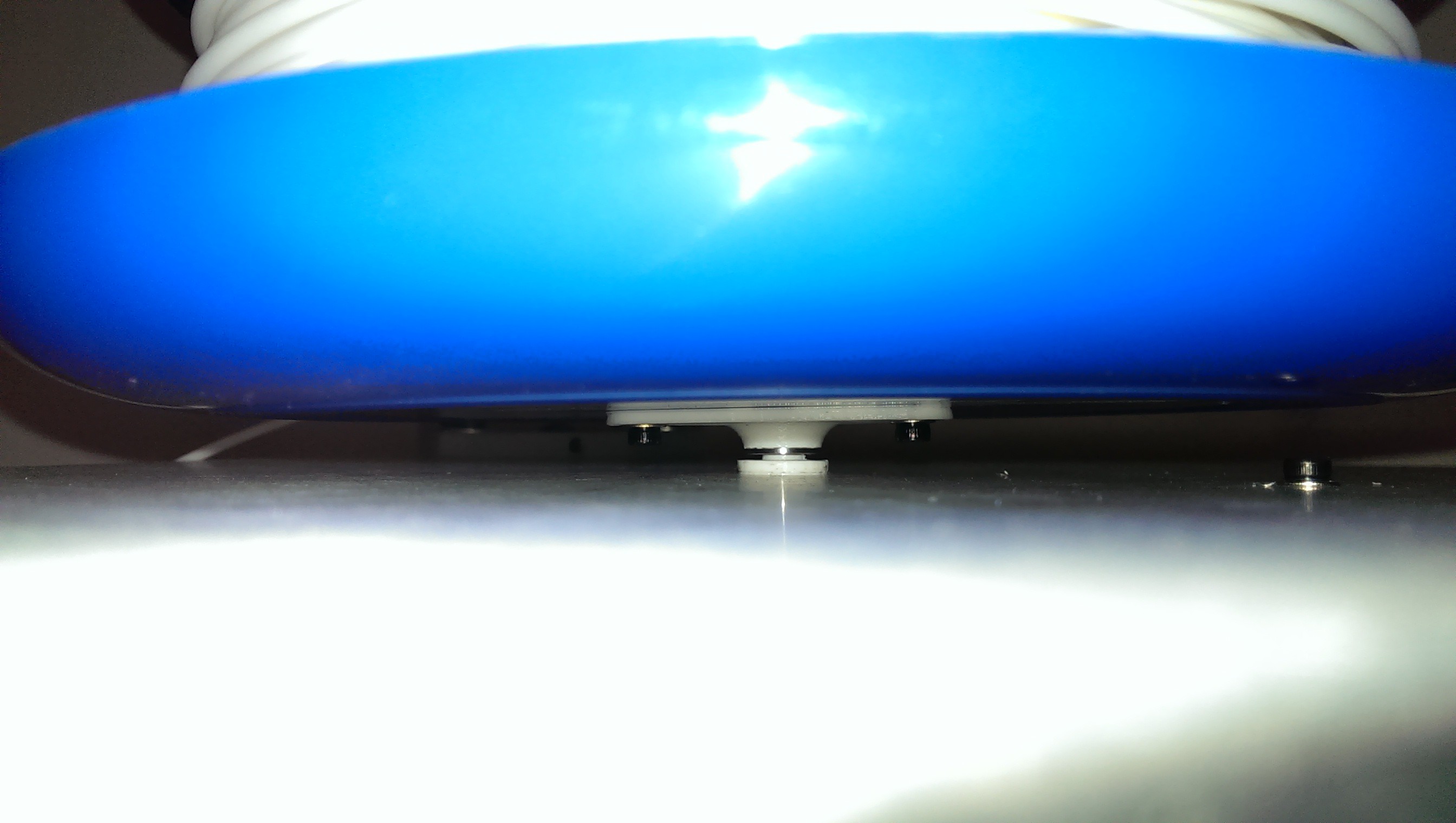
02/01/2017 at 09:34 • 0 commentsOne of the first things that most people print is some kind of spool holder for their printer. I was no exception to this routine. My design required that the filament spool be located on top of the top frame plate. There were a multitude of different designs on the internet but none really stood out to me. I was going through a junk box one day and found an old Frisbee. It turns out that the spool of filament I was using at the time fit nicely and even “self-centred” due to the curved inner edge. All I needed to do was print a small bearing mount for the middle. I had a few little flanged bearings left over from the idler pulleys which would work with this idea. I know that the bearings wouldn’t be operating in their ideal orientation (and loading direction) but I thought I’d try anyway.
![Free ANZ Frisbee from my uni days]()
Free ANZ Frisbee from my uni days
![It worked well]()
It worked well
-
Tuning
02/01/2017 at 09:29 • 0 commentsI chose to use Repetier-Host with Slic3r. I also considered Pronterface and Skeinforge but Repetier-Host appealed to me at the time (Q2 2014).
I did a lot of reading to learn how Slic3r worked and the effect of modifying each setting. I liked the fact that Slicer was so configurable and their documentation seemed decent.
Thingiverse has hundreds of test and calibration prints for tuning all types of different scenarios. I spent a lot of time tuning. Adjust a setting, print, adjust, print, adjust, realise a different setting is also impacting, adjust, print, etc.
I focused on the following:
- Dimensional accuracy
- Wall thickness
- Overhangs
- Stringing (Retraction)
- Optimal layer height
- Bridging
I would generally attempt to print something then realise half way through that it could have benefited from a small adjustment. It was really difficult to tune the settings for all types of objects. Settings that work great for one object might just not work for another object.
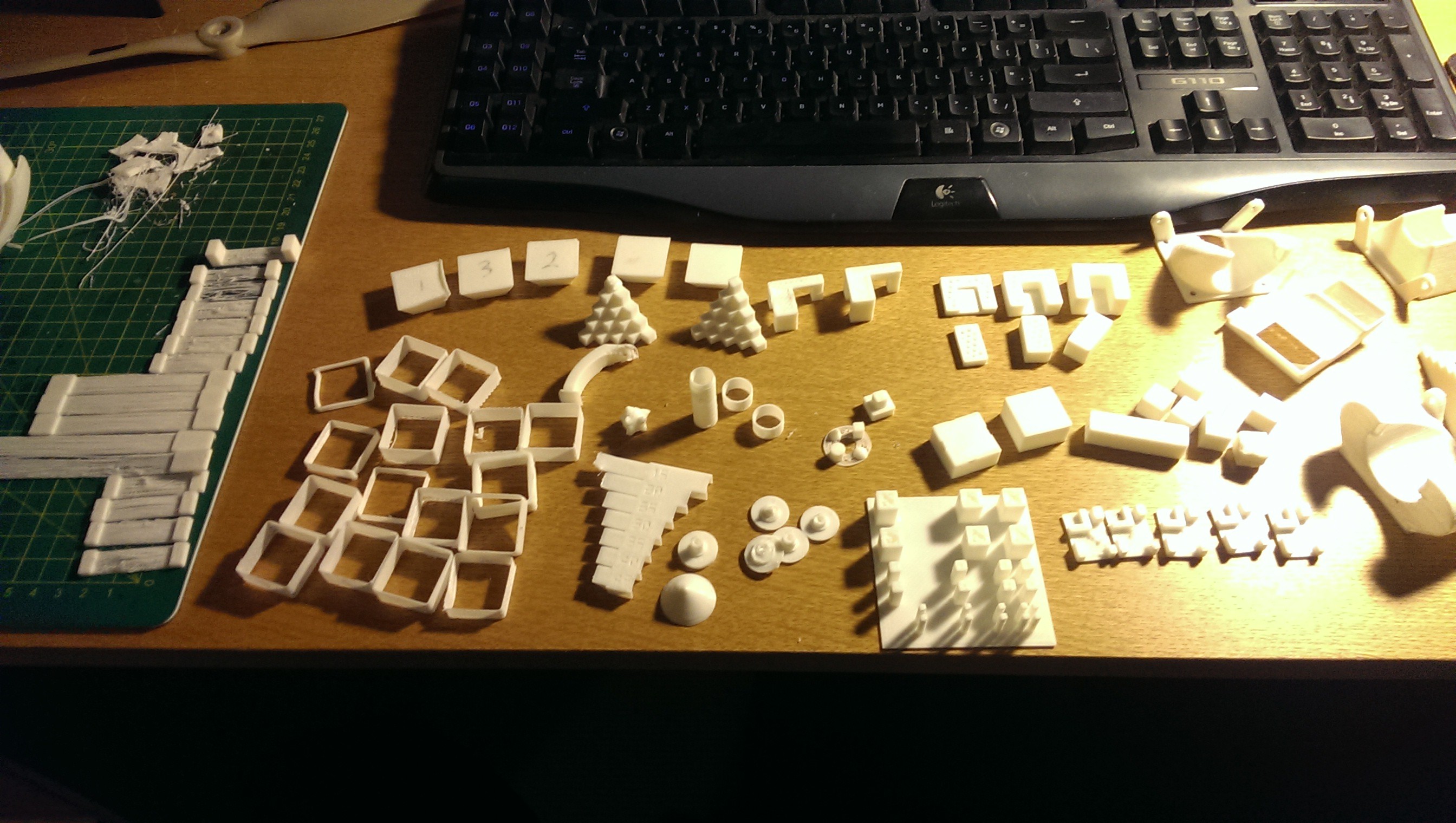
I probably spent about two months tuning to a quality I was happy with.
![A selection of test prints- bridging, thin walls, overhangs, stringing, tolerances etc.]()
A selection of test prints - bridging, thin walls, overhangs, stringing, tolerance etc.
Sometime in 2015 I tried using Cura for a little while. Out of the box it required minimal tuning and produced decent quality prints. Prints were also much faster due mainly to lower default perimeter/shell counts and infill density. The main reason to try it was the feature of printing multiple objects sequentially rather than at the same time. I found this perfect for printing spinning tops for some children at a school demonstration. I believe other hosts could do it at the time but Cura seemed easiest.
![Sequential spinning top handles]()
Sequential spinning top handles
Tuning is a constant activity as printing every object provides new challenges.
-
First Print!
02/01/2017 at 09:17 • 0 commentsI made a short video of manually moving around the platform to see how it all worked. Belts were disconnected for this test.
Once everything was hooked up I was ready for my first calibration routine. Using Repetier-Host, I manually jogged the nozzle to the base of each tower. I used a thin piece of receipt paper to get the height right. If the nozzle was too close or too far I would bend the legs of that tower’s endstop hall effect sensor just a tiny amount. Homing the printer each time resulted in an adjusted height for that tower. I did each tower a few times to “zero in” on an acceptable tolerance. An advantage of designing most of the printer in CAD first was that I could virtually measure the delta radius and it would be correct for the real printer. This figure required no adjustment and I had no issues with “bowling/bowing” of the Z plane.
I was pretty keen to get printing so started my first “dry run” print (no hot end, filament or heated bed). This was to test that the printer could receive g-codes from the computer and move in the correct X-Y-Z directions.
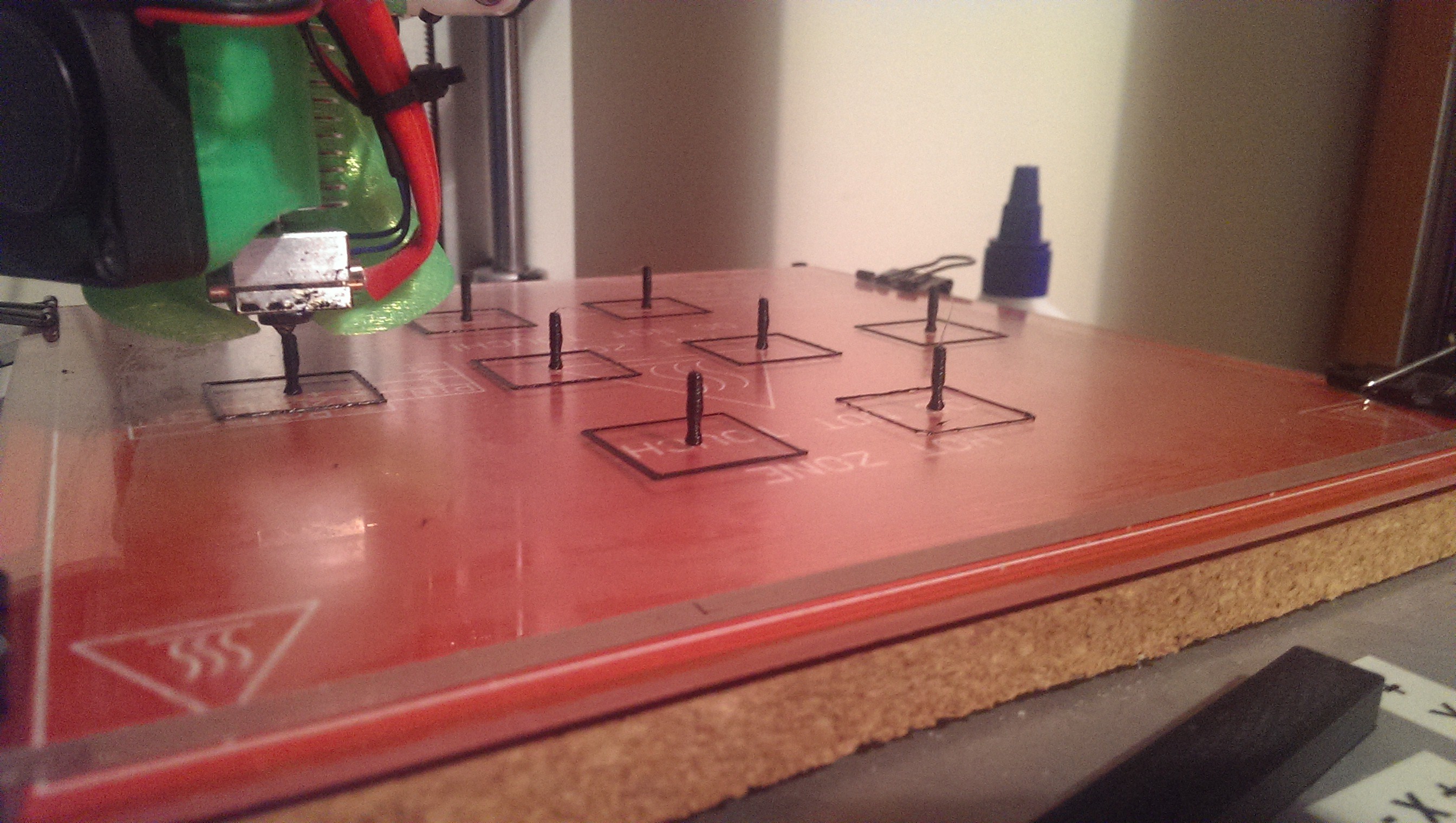
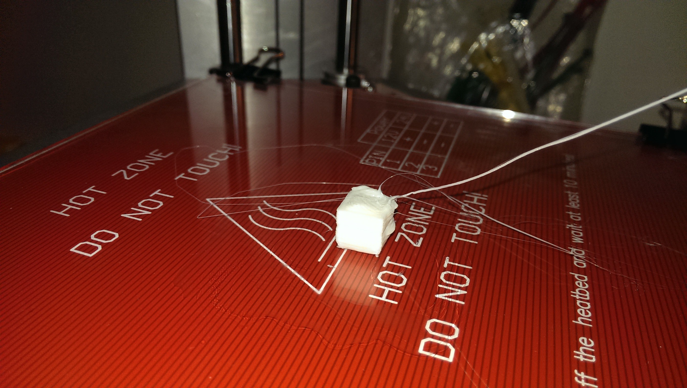
Not long after that I attempted my first 1cm cube!
The average result was to be expected. I didn’t care - I was so excited that my printer (somewhat) worked!![]()
Yay!
Obviously it needed some tuning but I was off to a good start.
-
Heated Bed
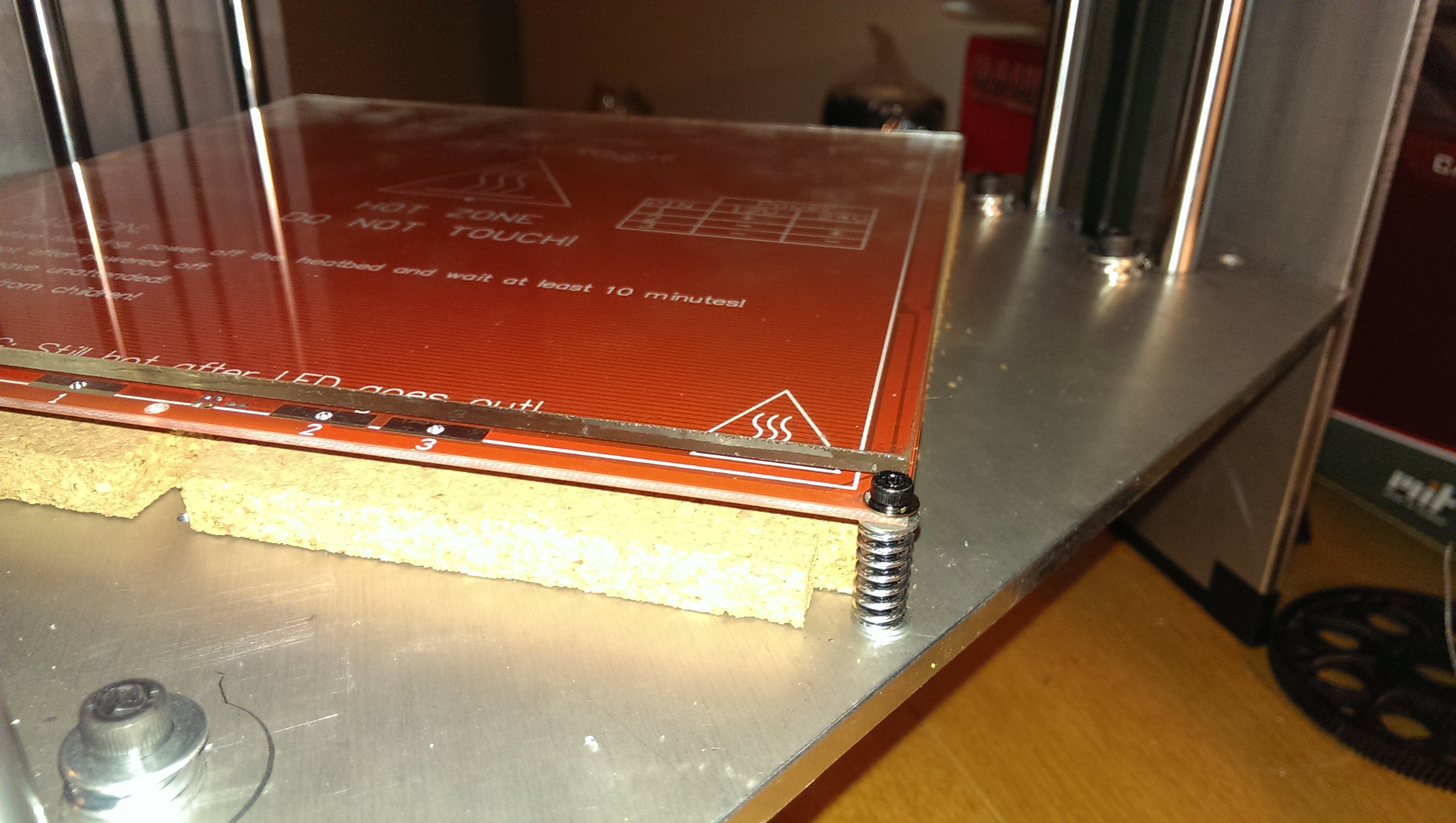
02/01/2017 at 09:12 • 0 commentsThe heated bed was mounted on all four corners. There was provision for a three-point mounting system (to aid levelling) but I figured the borosilicate glass plate would help keep things level. I used the springs provided in the kit to mount it the standard adjustable way. Again, tapping a thread into the aluminium was very neat. Bulldog clips were used to hold the glass to the bed. The heated bed setup was a pretty standard affair for 3D printers.
![Heated bed, borosilicate glass and cork placemat]()
Heated bed, borosilicate glass and cork placemat
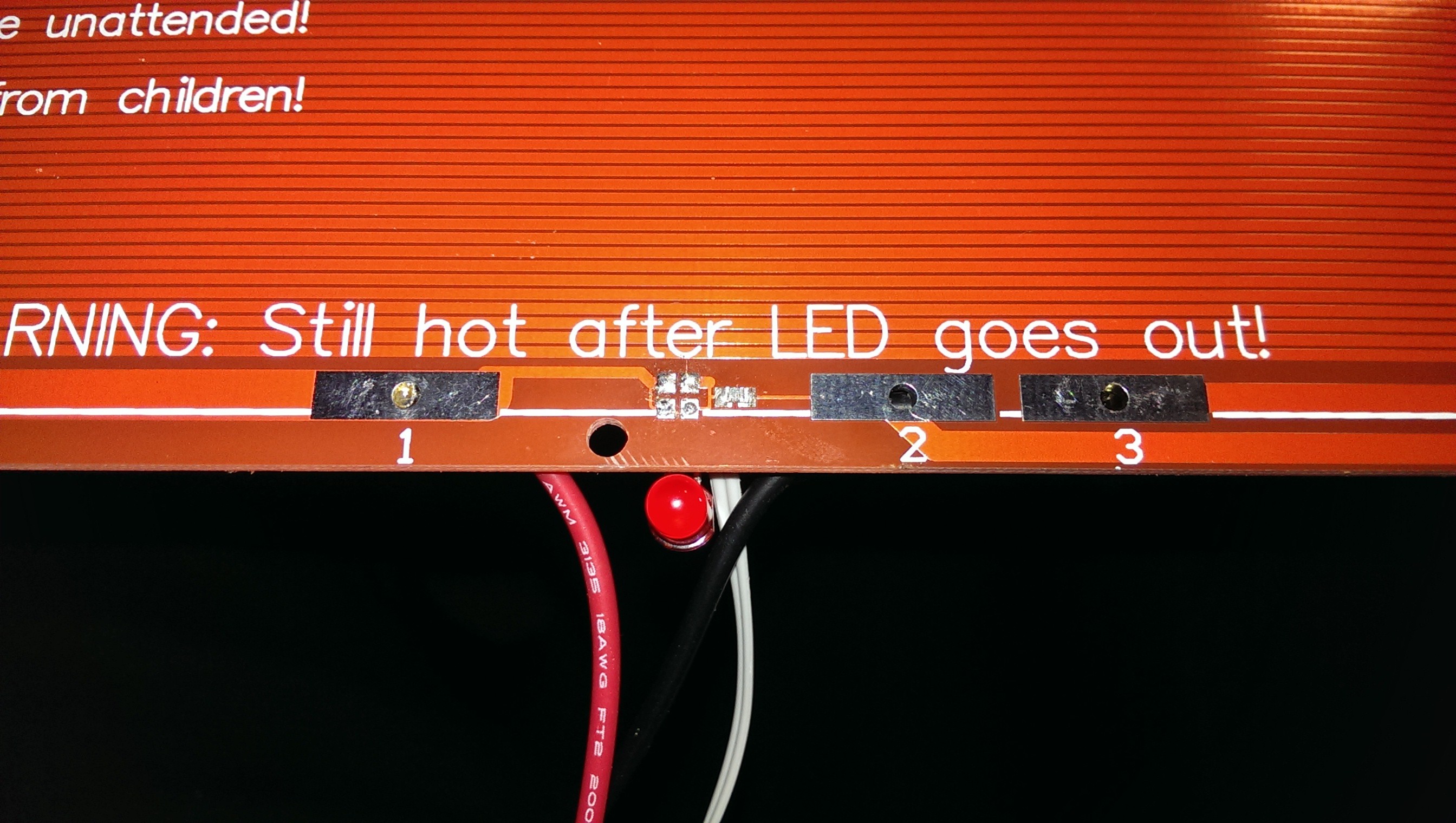
There was a small SMD LED soldered to the edge of the board to show when the power was connected. Unfortunately, it came soldered to the wrong side of the board (I know the MK2B heated bed can be used either way up). I managed to ruin the LED trying to desolder it so just replaced it with a regular sized LED and new resistor.
![Oops!]()
Oops!
To improve bed adhesion, I used diluted PVA in water. The solution was spread onto the glass with a small paintbrush while the bed was warming up. When the bed was levelled accurately this resulted in excellent first layer adhesion. Corners of parts stuck to the bed throughout the print and I had zero warping - even on big parts. Parts were nearly impossible to remove until it had cooled down to room temperature. Once cooled, prints would pop off easily. Occasionally a thin wedge (razor blade) was required to “crack” it off.
-
Endstops
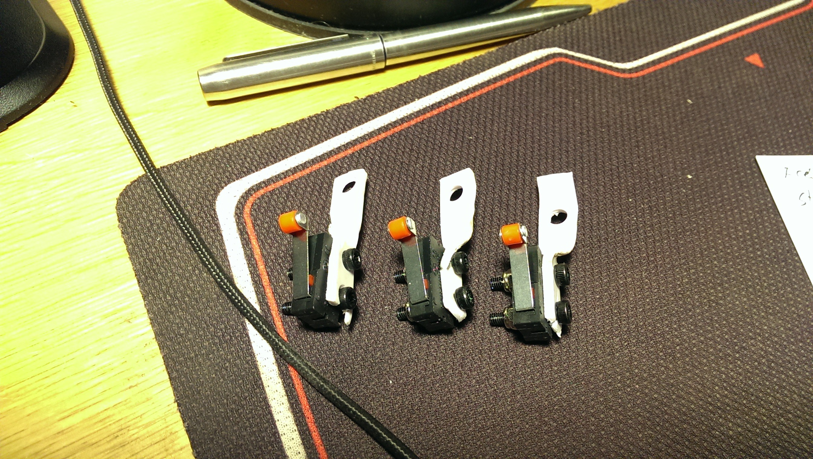
02/01/2017 at 09:08 • 0 commentsI originally intended the endstops to be micro switches. I read about how important homing was for delta printers and decided to scrap the micro switches pretty early on. Hall effect sensors were highly regarded with great accuracy and repeatability. This is mainly due to no actual touching of the sensor by the axis slider. There were premade hall effect endstops available but I knew I could make my own much cheaper. A little bit of googling later and I found some hall effect sensors with a handy little application circuit in the datasheet - perfect. The sensors I chose were Infineon TLE4906L from RS Components. I also bought some 5mm disc neodymium magnets to trigger them. The magnets were glued to the top of each vertical slider.
![Micro switch endstops with dodgy brackets]()
Micro switch endstops with dodgy brackets
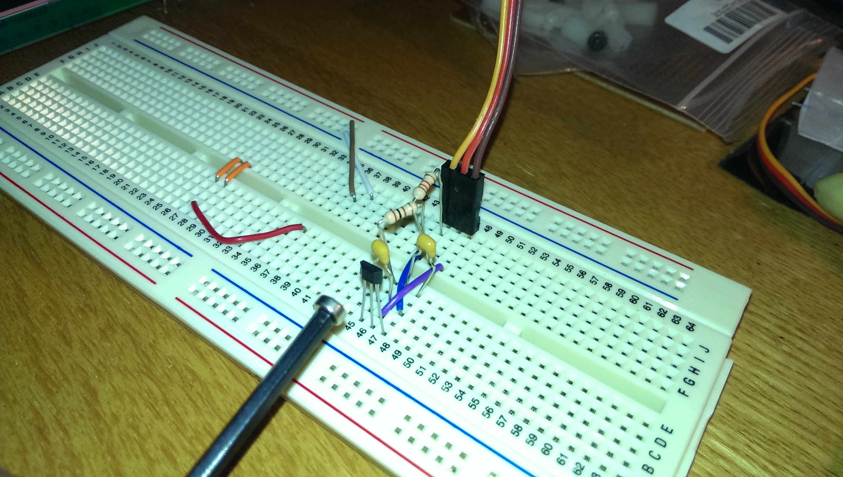
![Prototyping the hall effect endstops]()
Prototyping the hall effect endstops
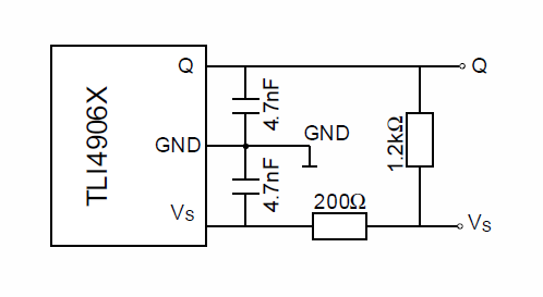
![Application circuit from datasheet]()
Application circuit from datasheet
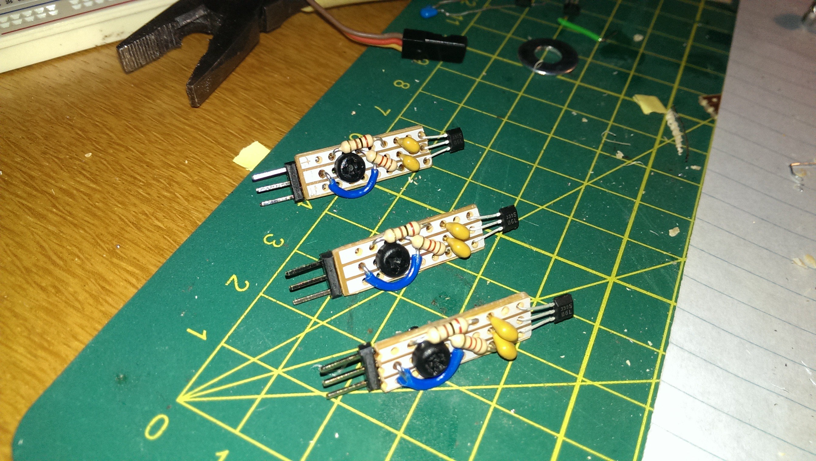
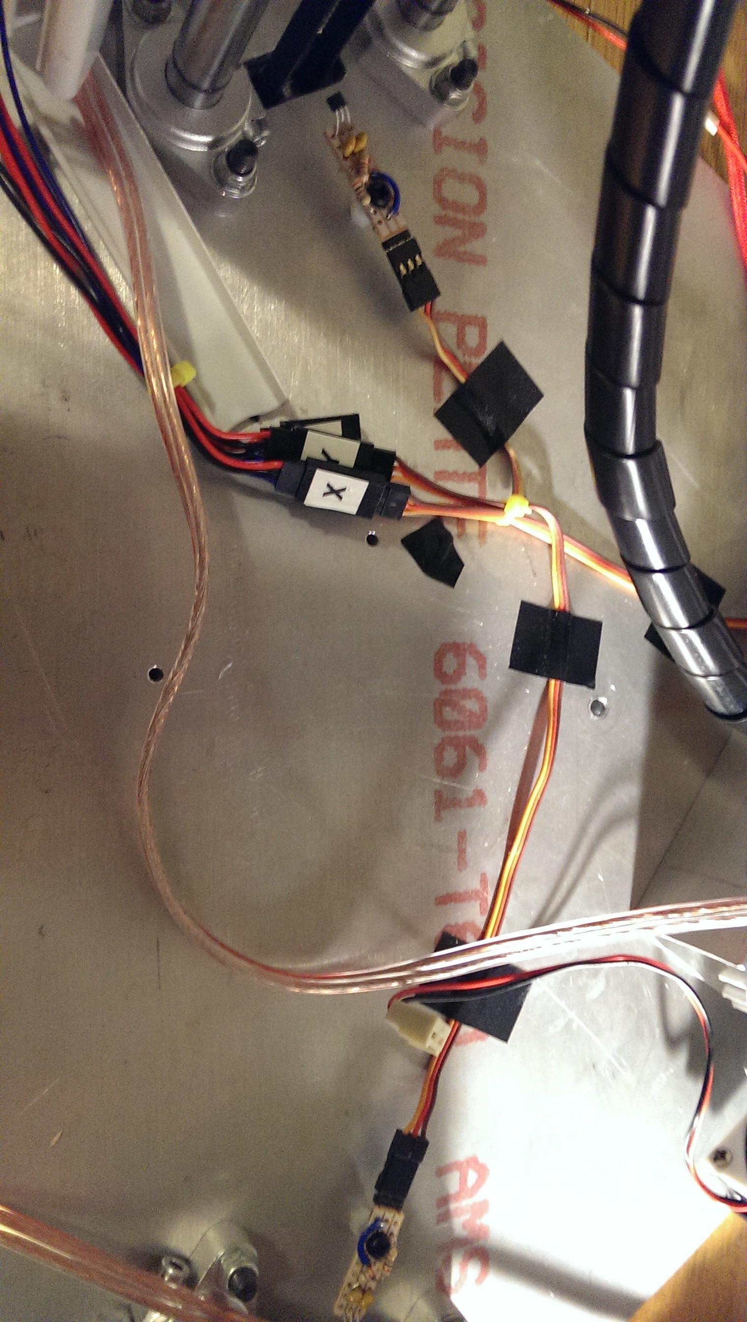
I had had some strip board and made up the endstops. They are mounted on a nylon standoff and can be adjusted by bending the legs of the sensor slightly. This would effectively change the trigger distance and adjust the axis when homing. I knew that this was possibly not the best idea but you only need to adjust them after moving the printer so it wouldn’t be very often. I also ensured that they had a “standard” endstop interface (+5V, GND, SIG).
![Endstops ready for installation]()
Endstops ready for installation
![Mounted under the top plate]()
Mounted under the top plate
I was really happy how they turned out and they worked great with high repeatability.