 John Adams
-
Go, Robots, Go!
12/21/2016 at 19:51 • 0 commentsUpdate: Thanks to Neil for correcting some of my (bad) assumptions about parts.
Update 2: It turns out that KiCad doesn't merge plated-through and non-plated-through hole drill files by default. I had to email the NPTH drill file to them separately. Next time, we will merge our drill files with KiCad or gerbmerge before sending.
Officially, our 'first spin' is underway!
Last night I managed to send off our prototype boards to Macrofab. Our estimated delivery date is January 17th.
I was torn between Macrofab and Tempo Automation, but ended up using Macrofab for the prototype because their bill-of-materials editor was far better. Macrofab's process walks you through the bill-of-materials. Tempo basically says "No, really, upload a CSV and we'll send you a quote."
Tempo was very, very nice to me on the phone, and I really want to support them because they're in SF, but I don't think their site is very easy to work with. The BOM search tool needs a lot of work. When they cannot locate a part in your uploaded BOM, they send you to a search page on on mouser or digikey, and after you find your part, you have to copy and paste that on Tempo's site.
Macrofab searches for you, in the same window, and allows you to easily click and select the part. This is a huge win.
What did we learn in this process?
- House parts are always cheaper. Base your design on what is available at the fab-house. You will save money on placement fees and parts.
- It seems that 0805, SOT-23 (transistors and otherwise), and SSOP are currently the best parts to use in SMD. There's a good balance there of hand-solderable/fixable and cost. It also seems like the 0603 LEDs were cheaper, but only available in Red and Green. Hey, Macrofab, what gives? No Blue LEDs?
- Avoid BGAs! BGAs require high-end tools to reball, repair, and fix. You probably don't have a $3000 oven or hot air tool.
- Don't use 1206. When I tried to use 1206, my prices went way, way up and parts were not available. The industry seems to be using 0603 mostly, but 0805 seemed to be a good balance for hand-soldering and repairability. Your iPhone probably has microscopic 0201 parts in it but there is no way I could ever work with those without a microscope and the steady hands of a surgeon (or robot.)
- RoHs is a great standard for (somewhat) environmentally friendly electronics work -- All electronics work is environmentally hostile, Don't act like it isn't! However: RoHS parts cost more. Fact: All but one of our parts (the JST battery jack) is RoHS compliant.
- Consignment saves money. if you have the time-to-market and can ship parts, it will greatly reduce costs. Example: 12 WS2812 Leds are around $11 on Macrofab's site, or a Tape Reel of 1000 are $60 from China.
- We will probably consign batteries, touch screens, and LEDs from China to make this project go.
Ideally, work your project in the following order:
- Schematic and Component selection first, based on...
- Match components to the BOM of the fab house. Use the Macrofab KiCad libraries so you don't have to guess or look up parts. Download them at https://github.com/MacroFab/EDALibraries/tree/master
- Use that to dictate foot prints for the PCB. Place footprints before you try to route at all!
- Move all of the decoupling caps in place on your board next. Also make sure things are together (i.e. pullups near pins, resistors near their companion LEDs, etc.)
- Why? Because placing footprints after things are routed is very hard!
- Place mounting holes BEFORE any routing takes place. Note that if you import the net list again in KiCad, it will remove all of the mounting holes. Write that shit down in your notebook once you figure out where the holes go, or back up the kicad_pcb file so you have a copy of the mounting locations.
- If you add mounting holes as components to the KiCad schematic, KiCad will not destroy your mounting holes every time you reload the net list.
- Also, don't be stupid. A 3mm mounting screw goes into a 3.2mm hole, not a 3mm hole. You must allow some clearance for the bolt.
- Set Design rules, based on the rules of the fab BEFORE you route.
- Then: Position the components, by hand, matching the fab's design rules.
- Install freerouter. It is an abomination written in Java. Deal with it, it works and works well.
- Run Freerouter. Do not be afraid to stop it if it gets stuck and manually route.
- Repair the autorouter's mistakes / make things sensible.
- Don't add ground layers to the board until everything is 100%. It's too confusing otherwise. If you are using a round / robo-bender / artwork / strange board shape, don't panic, just draw the ground polygon around the entire board and let KiCad sort it out. Tie that net to ground. Duplicate the ground shape and flip it (if necessary) for the other side of the board.
- I'm told that the practice of via-pinning or via-caging (putting vias all around the edges of the board to create a mini faraday cage for internal layers) isn't really used these days. I saw it on the Ninja Networks badge in 2010, but I don't think we're doing it unless we have clock noise or issues with the radio.
- Last, confirm that none of your traces are near the edges of the board's edge cuts.
General build notes / mistakes
- KiCad UI - I dealt with days and days of UI pain, so much so it made me feel nauseous as the screen would zoom in and out randomly. It turns out that the Mighty mouse on my Mac Pro didn't get along well with Kicad. To fix, do the following: Enable Trackpad Panning in Preferences. Then, go into the hotkeys editor and map Zoom in, Zoom out, and Zoom to region to "1", "2", and "3". Your left hand goes on 1,2,3, your right hand on the mouse. Modify this if you're a southpaw, but you'll love it after ten minutes of use. Trust me. Also Command-0 is your friend to reset the screen to something sensible.
- Four layer = more expensive than two layer. strive for two layer when possible (not so easy to avoid 4-layer on VLGA chips, like our KW01) We see a near 1.6-2x cost increase when going to 4 layer. As much as it is going to suck, I am going to attempt to make the production run 2-layer.
- Custom silkscreen colors = don't do it in short runs. There is a minimum board limit with very strange boundary conditions at Macrofab. I think given our board size it was 109 boards before we could take advantage of the custom color cost
- USB Ports: There are an incredible number of different USB ports out there. Make sure you buy the right one and your footprint matches, or just give up and use Macrofab's USB_MICRO_RIGHT and call it a day.
- Clearance: I am currently in a panic over the hole/drill clearance on some of my parts as well as the silkscreens. Advanced Circuits offers a free DFM check tool that unfortunately takes about 12-24 hours to mail you back, but it is very good in finding mistakes. "Potential Showstoppers" found here might haunt you later. I have some vias to move, sadly.
- Test pins: For the love of his noodlyness: rename the damn test pins on your board. I forgot to do this and now I am going to pay for it. We will fix this. "W1" means nothing when testing. "SPI1_MISO" means something.
I used KiCad. KiCad is buggy as hell, but I got through.
The library management is garbage and failed constantly. I had to resort to hand-editing files to get things done, especially when we would do a major change (like a component footprint) and then have to update the board.
Additionally, I had to get a same-day patch to stop the design-rules-check from crashing. Without the kicad nightly builds I wouldn't hve been able to build.
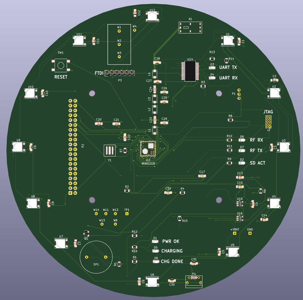
After all that, you'll get something like this:
![]()
if you want more information about Macrofab and KiCad, there's a nice video about some of this from the And!XOR guys here:
-
Boards, BOMs, and Finding parts.
12/16/2016 at 21:17 • 0 commentsIn the last few days I've managed to compile freeroute, overcome numerous KiCad issues, build another functioning prototype, and actually get the board to succeed with all paths routed. Unfortunately it took over 13,000 passes in the autorouter to route and optimize the board (a few hours of CPU time on my MacPro.)
We're learning many things the hard way, unfortunately, but at least we are learning them.
First off, most of the parts that we decided to use, were 1206 SMD parts. The world has moved past 1206 as best I can tell. I don't want to use 0405 (too small) or 0605 (small), but there seems to be a sweet spot with manufacturing houses and the 0805 part size.
Most LEDs are 1206 or 0805, and the small picofarad caps in our RF section are only available in the 0605 size, so I think it's time to redo the entire schematic with the express plan of 100% fabrication at the fab plant.
The parts that we use are going to be largely dictated by common parts available at MacroFab or Tempo Automation, the two vendors I think I'm going to go with to build the boards. Small changes (like using different headers, device sizes, or antennas) move the price dramatically, by nearly $20-30 per badge. We have to be very careful with our part selection.
Part selection seems to be easiest on MacroFab -- they have an export utility, so I can pick all of the common parts and then
Our big problems are coming from trying to source the KW01 CPUs. Some 200 are available through mouser, zero are available at digikey. It's an 11 week lead time on these parts and in some cases the minimum order is a 2,000 tape reel. I am not spending $8k on CPUs.
I've also learned how to solder 0405 bridges on the dev board with tweezers and a magnifying lamp. That sucked and left me begging to own an AmScope. I highly recommend you have a needle-tip soldering iron, flux, and tiny, tiny solder. At least I had needle tips for my Fluke DVM so that I could verify my connections at this scale.
Have I mentioned how Louis Rossman is my hero for SMD work? Go look: https://www.youtube.com/user/rossmanngroup
On the software side of things, Bill has badge-to-badge radio chat mostly working (which is pretty neat), and I have completely rewritten the fight-game event loop to be more compact and use a single radioHandler to change state. Before I was using five handlers and it was extremely ridiculous trying to manage the in-memory structures and handler enabling/disabling. Now, a single state machine runs the entire game.
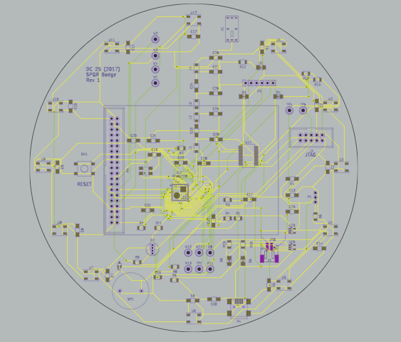
I'll leave you with a photo of my first attempt at the board, but unfortunately all of this is about to change.
![]()
-
PCB Design. We has it.
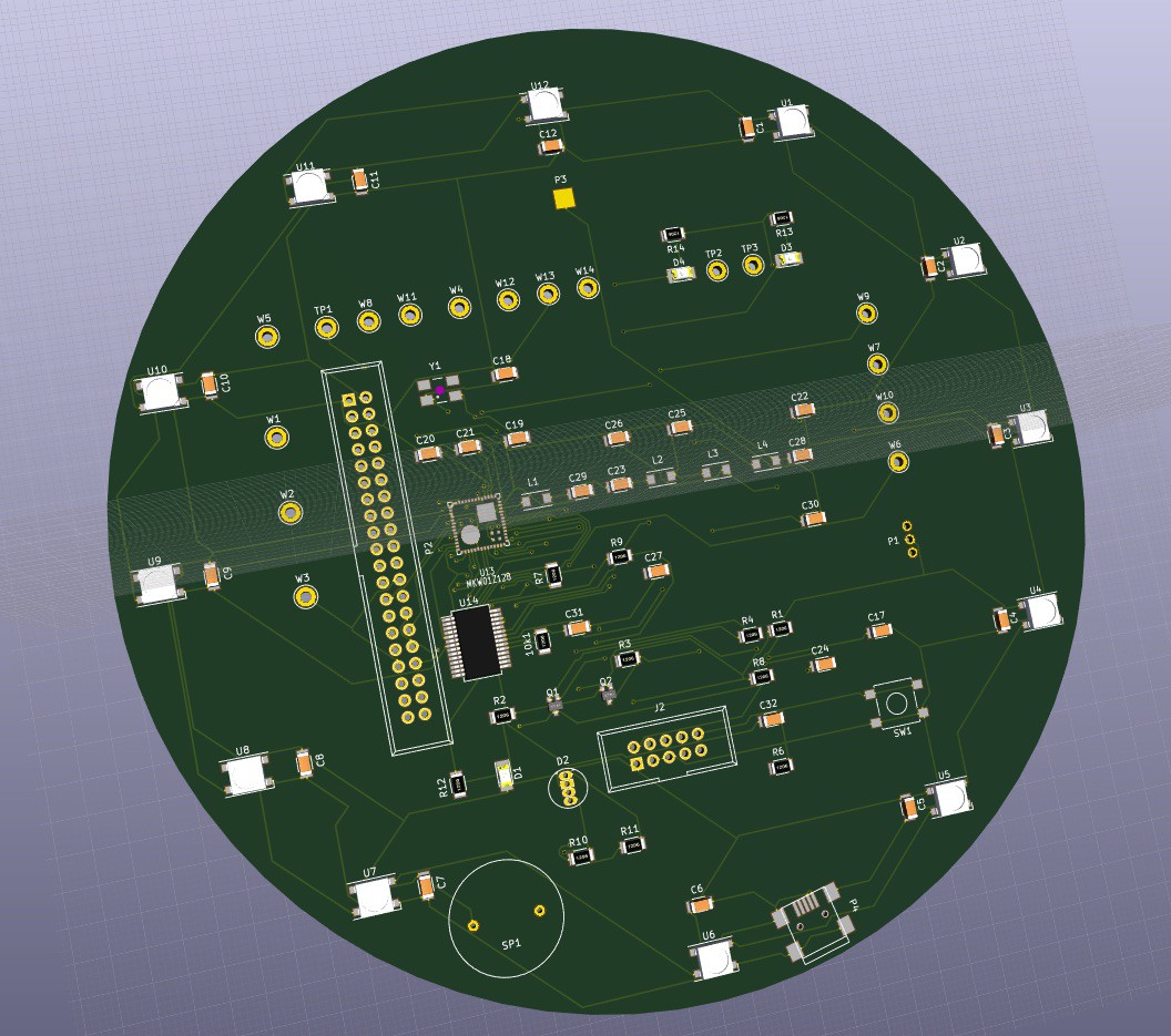
12/12/2016 at 06:00 • 0 commentsWe're about 90% done with our schematic, and about 80% done with the board prototype.
I've actually gotten much better at kiCad and have nearly all of the parts on the board. I'm unsure about the final shape, but here's a quick preview.
Remaining HW tasks:
- Sort out the Battery / USB Charging / LDO / Boost regulator / Power issues (oh so many power issues.)
- Attempt to test the FTDI schematic (I copied it, I didn't test it at all) and console access via USB.
![]()
-
Letting out the magic smoke.
12/09/2016 at 23:28 • 0 commentsWe had two boards, functioning and talking to each other for a grand total of two hours.
I somehow managed to cook the OpenSDA chip on my board, making the entire board non-functional. A $200 mistake. Now we wait for a Digikey shipment. Siiiiigh.
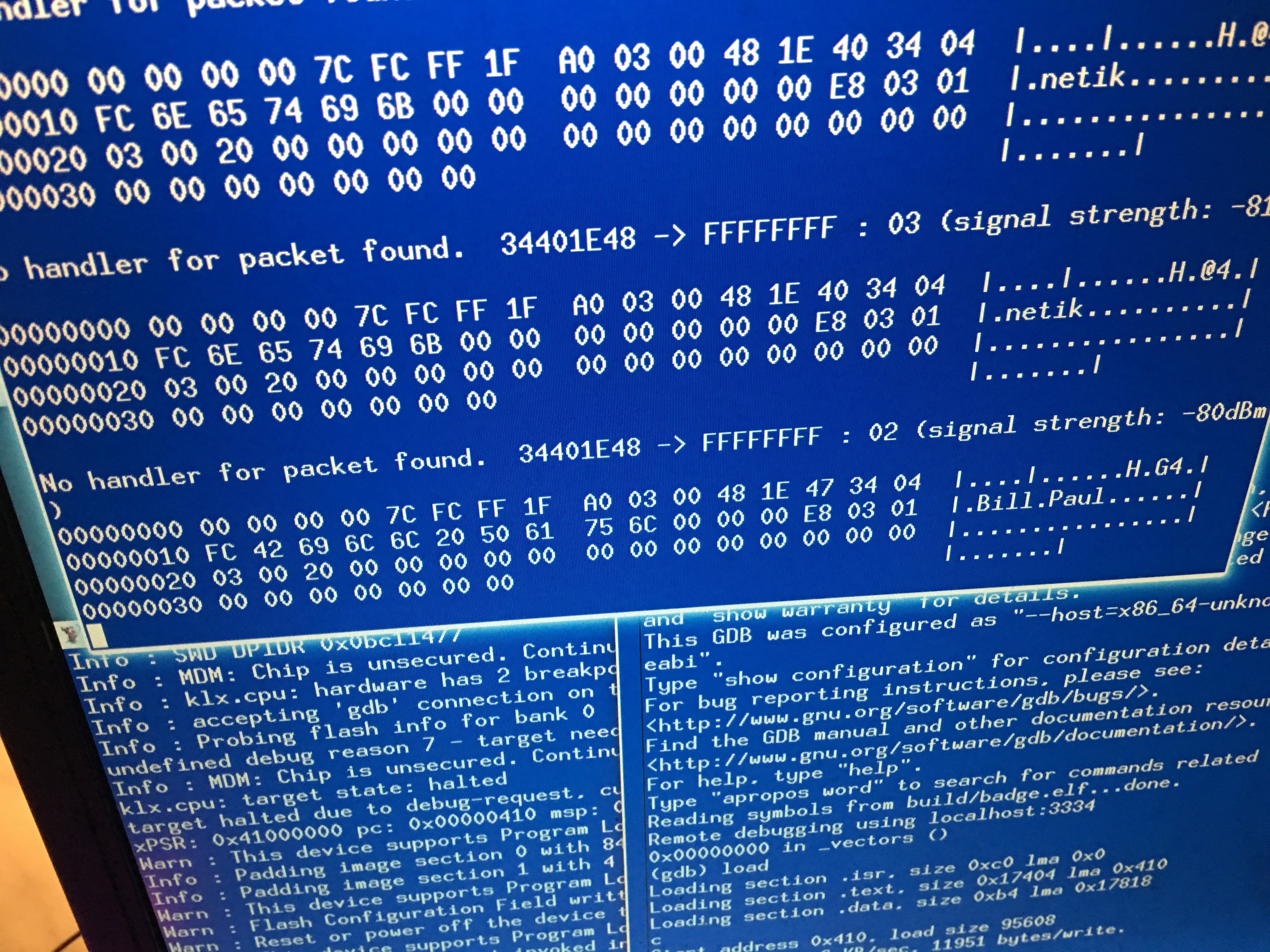
However, with the one remaining board and around 20-30 hours of work I've managed to write a fair chunk of the game.
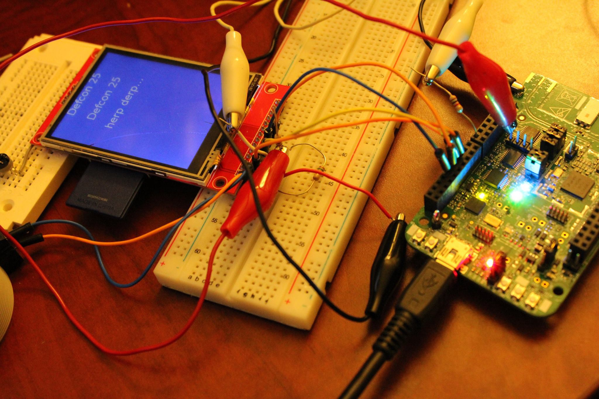
Here you can see the radio default packet handler actually receiving data from both badges and the beacon transmissions from the badges. that other junk in the packet is the user's stats, like level, hit points, and other game related stats.
![]()
-
Two boards, one RFIO
12/07/2016 at 06:18 • 0 commentsSo things are moving along quite nicely. Bill's ordered some extra boards and screens and given me back the second dev board. Now, I can actually test our the radio processing without having to mock up an interface. Pretty neat!
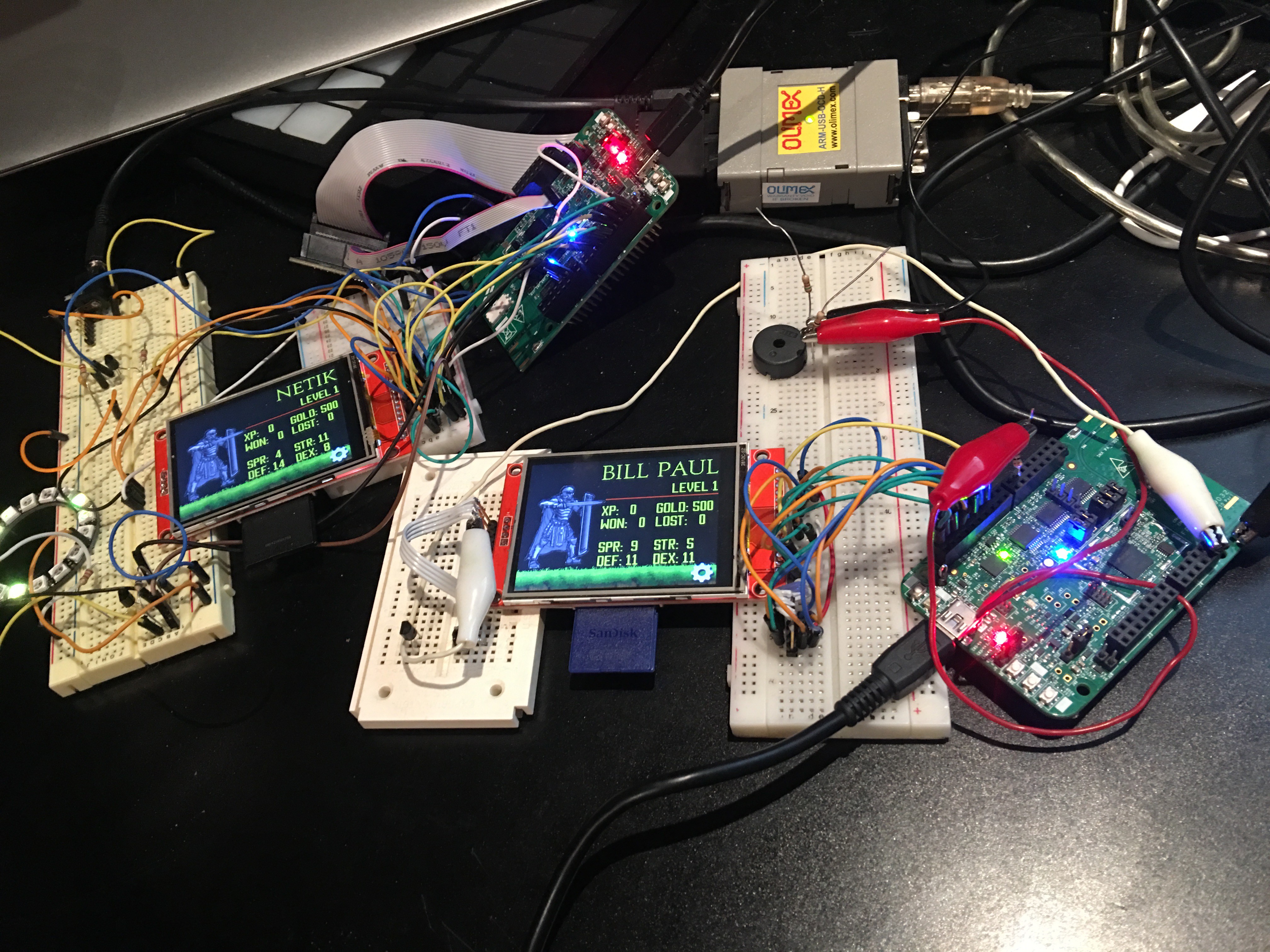
Here's our boards in one big pile:
![]()
Soon we'll have four fully working boards, which is enough to start testing multiplayer!
Our radios are up, we're beaconing, and at the point where the boards can see each other. With two boards each, we can finish the radio protocols for messaging and fighting.
Today, I added a transistor to the piezo circuit and cross-checked all of the schematics against the KW01 reference board. Adding the transistor and accompanying resistors has greatly increased the volume of our piezo, and made it quite loud, if not annoying!
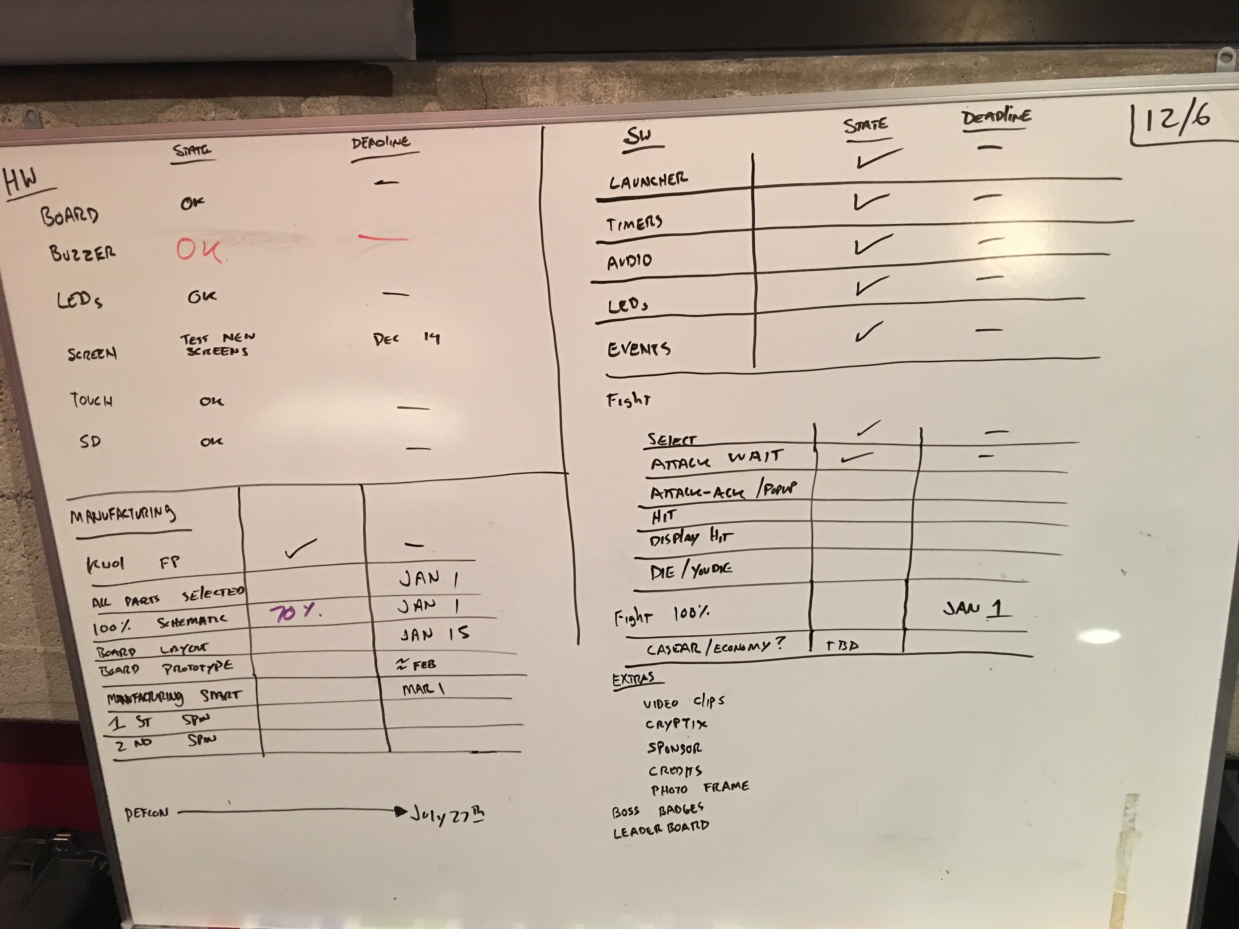
Our task list is up on the big board, and we're really getting there. Major milestones to accomplish next now include Battery, Charging, and FTDI connections. After that, I can lay out the board.
We can do this!
![]()
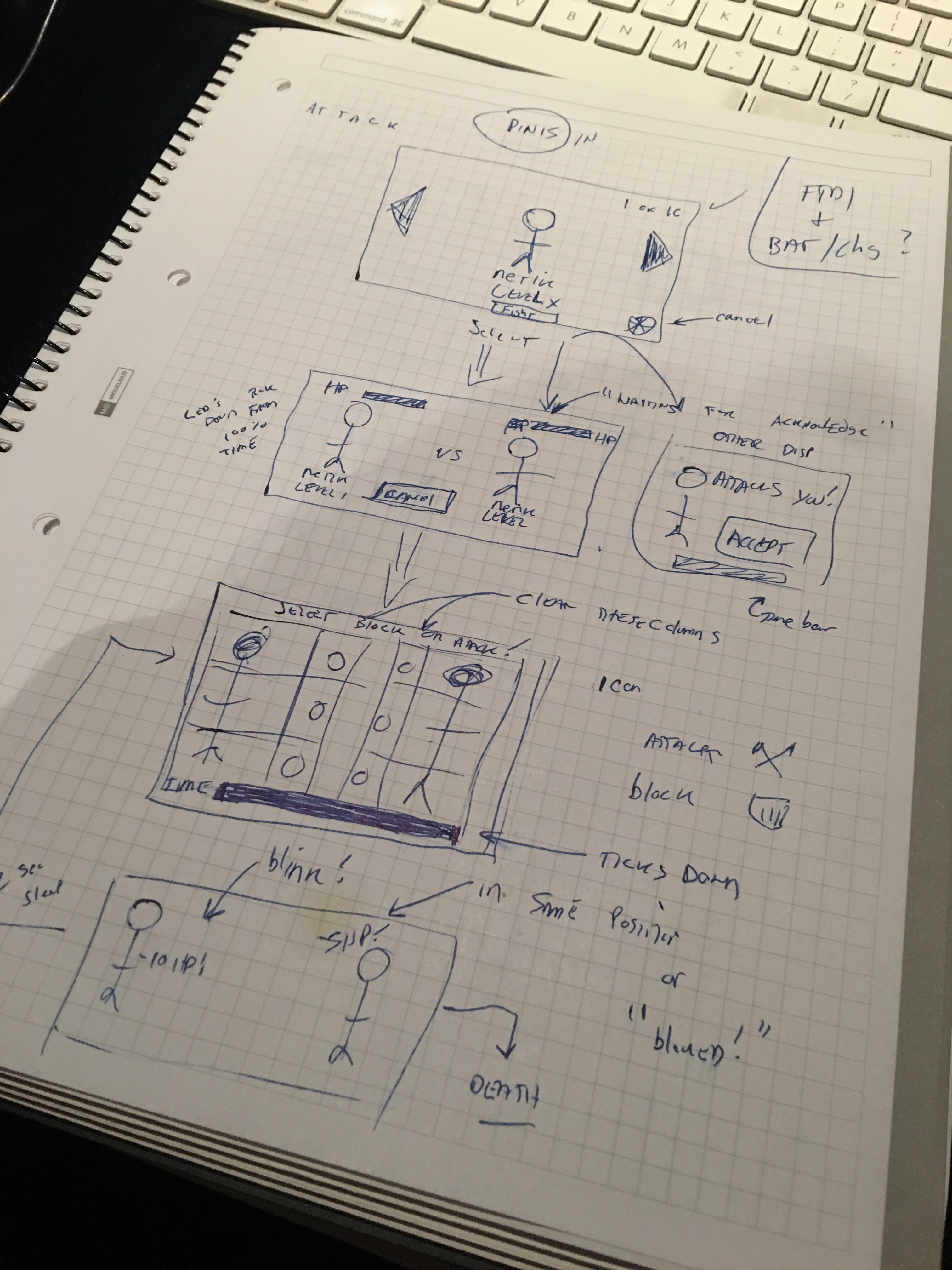
and Here's some sketches on how we think the game will work:
![]()
-
Photos
11/28/2016 at 19:26 • 0 commentsHope everyone had a good Thanksgiving.
Over the holiday break, we've made quite a bit of software progress. Huge, huge progress.
We integrated the Orchard events system with ugfx events, which gave us access back to all of ugfx's widgets (which we really don't want to rewrite.) We can read and write user state to the KW01's flash, and changes made to the device fully restore on reboot.
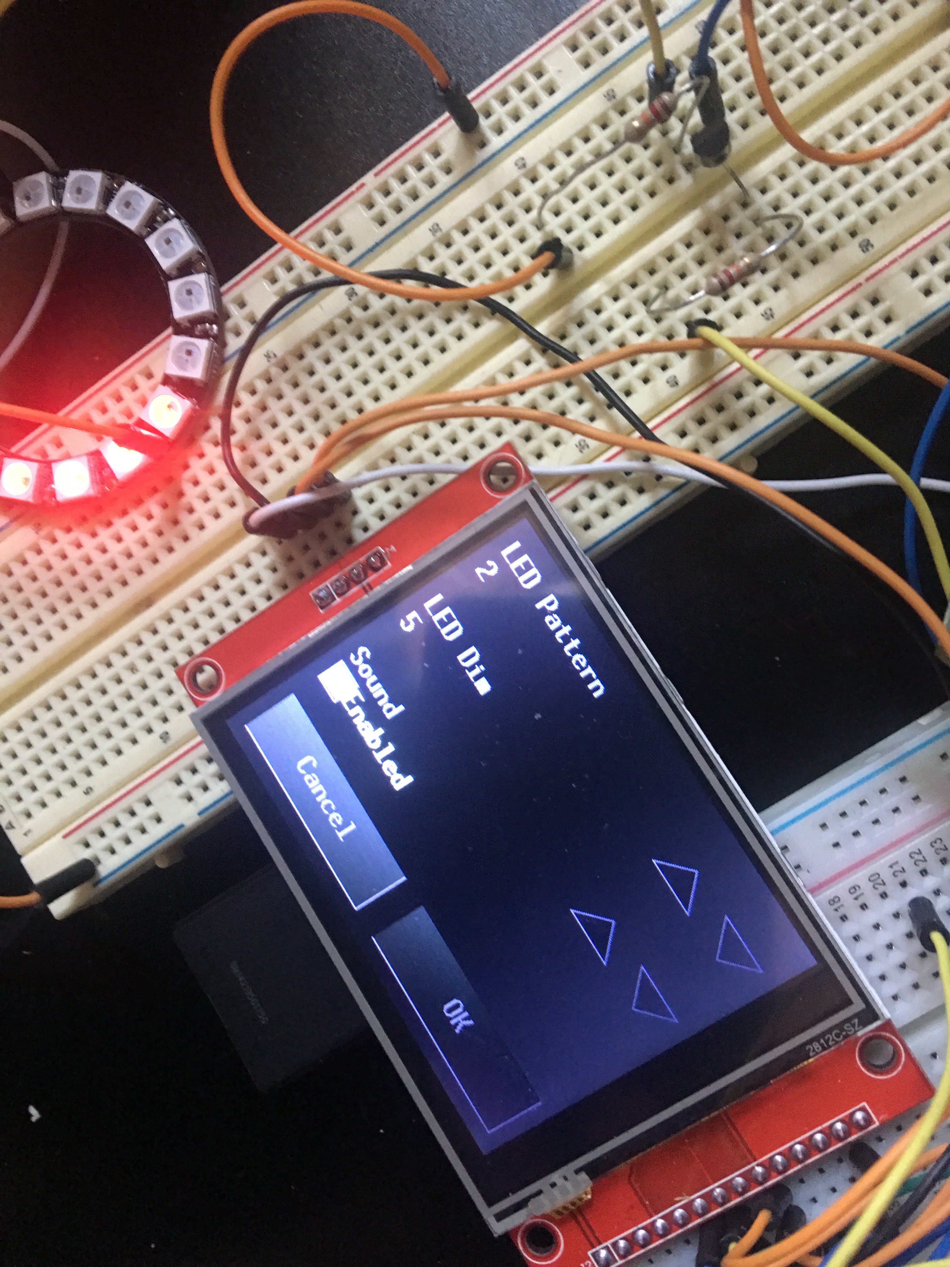
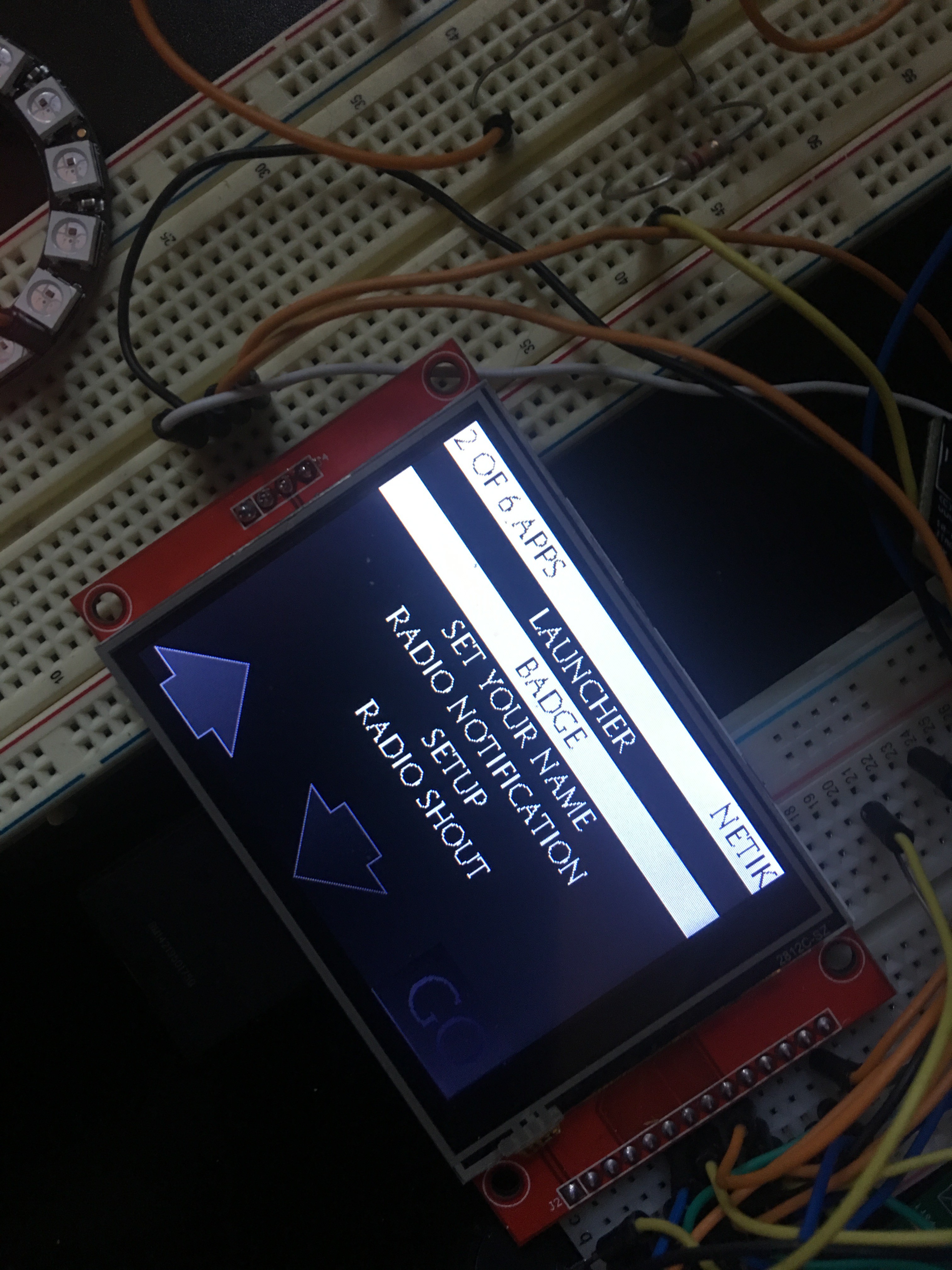
Getting UGFX events back was huge, because nowe we can make complex setup pages like these that respond correctly to touch. I think this is the first DEFCON badge I've seen that has a fully working color touch screen (not counting the Ninja Phone, which was a phone...)
![]()
Another big fix was getting access back to the launcher system. Adding new applications is as easy as creating a new app-XXX.c file and code. Orchard's init, start, event, exit application pipeline makes it easy to run any app we want while still being able to receive events from the radio, timers, and touch screen. Background threads keep our LEDs blinking, while the event system's callbacks ensure that we can clean up after ourselves when apps terminate.
![]()
So, as you can see above, font rendering in ugfx is simply awful. I've gone through about 15 fonts so far trying to find something that looks a) Roman/Old, b) is highly readable, c) doesn't look like a bitmap. As cool as retro-bitmap is, why should we waste this gorgeous screen?
In the Art Department, it looks like Matt Harris is going to help us draw our characters. I've already seen a couple (I'm not going to let you see them yet!) but he's made some awesome bitmap art that appears to load quickly on our boards.
We've refactored the image loading system so it's easier for me to drop images in, and are pretty much at a point where the game development can really begin. I'm very excited to see this thing come to life!
-
Climbing the Hardware Moutain
11/22/2016 at 23:22 • 0 commentsHaven't posted here in about a month, but major progress has been made. I was delayed greatly by not being able to program our KW01 boards through the Mac's USB port (although it worked just fine for Bill via FreeBSD.) A purchase of an Olimex USB debugger has fixed this, and as of today:
We currently Have:
- Working read and write to the SD Card
- All 16 LEDs working with ten onboard animations, selectable from the shell
- Functional touch
- Functional Color screen
- Sounds (piezo) and background playback threads for note list
- Graphic loading
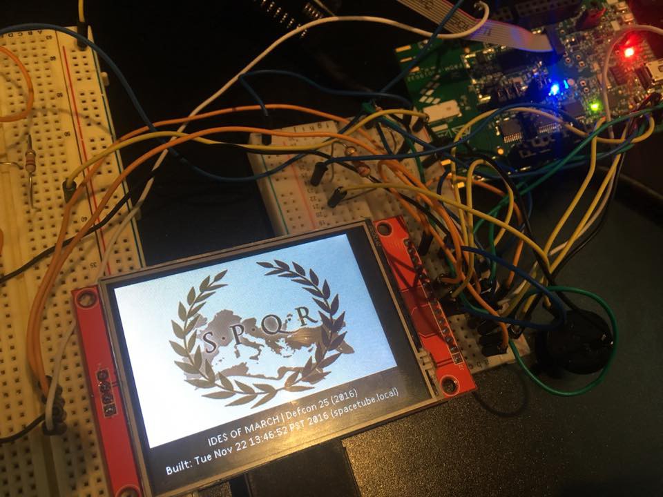
- Splash Screen and Event processing subsystem
- ASCII art and working TTY Shell(!)
What's left, you might ask? We're a long, long way from done. We still have to deal with:
- Fonts
- Art
- Event Hooks for radio, touch, keydown, orientation (DONE 11/24)
- Final game mechanics
- A list widget or two
- Flash storage for prefs and name/id (DONE 11/25)
- Game radio protocol and Game
- Idle reset timers and Idle Screen
- Battery + Charging
- Board Layout and Prototype #1
- ??? Hidden stuffs ???
So, I think we can pull that off between now and Jan 30th.
![]()
-
We have a display.
10/26/2016 at 18:58 • 0 commentsAfter waiting weeks, two screens arrived from China. They're both cracked but functional.
I think the lesson we just learned is: Order enough hardware that it arrives in a box, not a padded jiffy mailer. I gave one of those to Bill, and he managed to get the KW01 talking to the screen after much frustration and microscopic soldering!
![]()
The main problem so far is that updates are painfully slow and expensive. We think it might be an issue in the driver code (it apparently only writes one byte at a time. Very, very slowly.)
I've ordered a couple of Adafruit Neopixel (WS2812) rings to see if we can get the KW01 talking to those. I think it's going to be a major pain as I have to program the KW01's timers, but there appears to be a couple existing implementations we can use to drive the lights.
Our peripheral list is quite small: Audio, Touch, Screen, LEDs. Possibly an orientation/tilt sensor as well, but for each of these devices we must slowly work out how to make them talk to the CPU.
On the home front, I've got some new lab hardware on the way. I'm cleaning and taking out the bookcases in the office, putting in a desk, and adding various items like a PanaVise, magnifier lamp, and solder station. For years I've had my electronics tools strewn everywhere. It's time to get serious about this stuff given the project we're on.
I will probably end up with a hot air rework station and new oscilloscope at the end of this as well but I'm holding off on those large purchases until we make more progress.
-
Schematic Time
10/17/2016 at 23:18 • 0 commentsWhile we're waiting for those cheap touch screens to arrive, I've started to map out the initial schematic for the badge. If you're coming at this from an Arduino or Software Engineering background, it's incredible how much stuff you have to keep track of.
My desk is covered with data sheets, and I'm just starting to navigate the Freescale KW01 docs.
For me, there's a number of firsts in this project and that means a number of places to fail. This'll be the first time I'm working with: SPI, RF at 900Mhz, a 32 bit microcontroller, and SMTs. Up until this point most of my work has been on breadboards and on PCBs that did not make use of SMTs.
Fighting with KiCad hasn't been fun, but I'm making steady progress on the design. Next steps are nailing down how the touch screen and display will attach to the MCU, and QAing the design before I sent it off to a prototyping house for a one-off board.
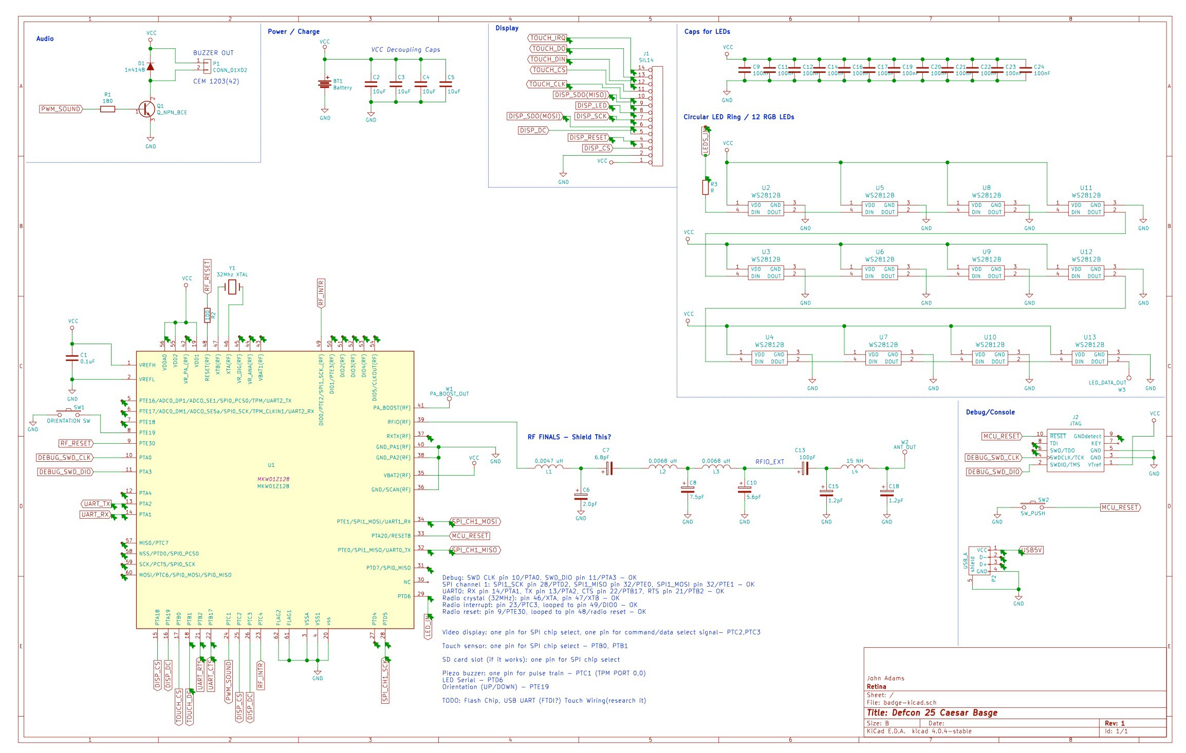
![]() I'll stick an image here so you can get an idea of what we're thinking about. The board design itself is still in flux, but I think the basic feature set is:
I'll stick an image here so you can get an idea of what we're thinking about. The board design itself is still in flux, but I think the basic feature set is:- 900 Mhz Radio
- Touch (Resistivie) screen
- Color TFT display (320x200)
- Tilt sensor (up/down orientation)
-- Such that if you flip the badge up towards you, we reorient the display and touch correctly. -
Screens...
10/11/2016 at 00:14 • 0 commentsFinding a proper screen for this project has been one of the hardest decisions we've had to make so far.
It determines everything from what the game will look like to how much our boards will cost to build.
In a perfect world we'd love to have color and touch, and still have a retro look (think: nintendo.)
Our leading candidate right now is
https://github.com/PaulStoffregen/XPT2046_Touchscreen
Which is a beautiful 2.8" TFT display with serial touch, sourceable from China for a mere $12.
If it works, and the power consumption is reasonable, I think we're moving forward with that display.
The ides of DEFCON: An Unofficial Electronic Badge
A wearable hardware badge, featuring blinky lights, sound, a sub-1Ghz radio, games, and more. Based on the Freescale KW01.
 I'll stick an image here so you can get an idea of what we're thinking about. The board design itself is still in flux, but I think the basic feature set is: