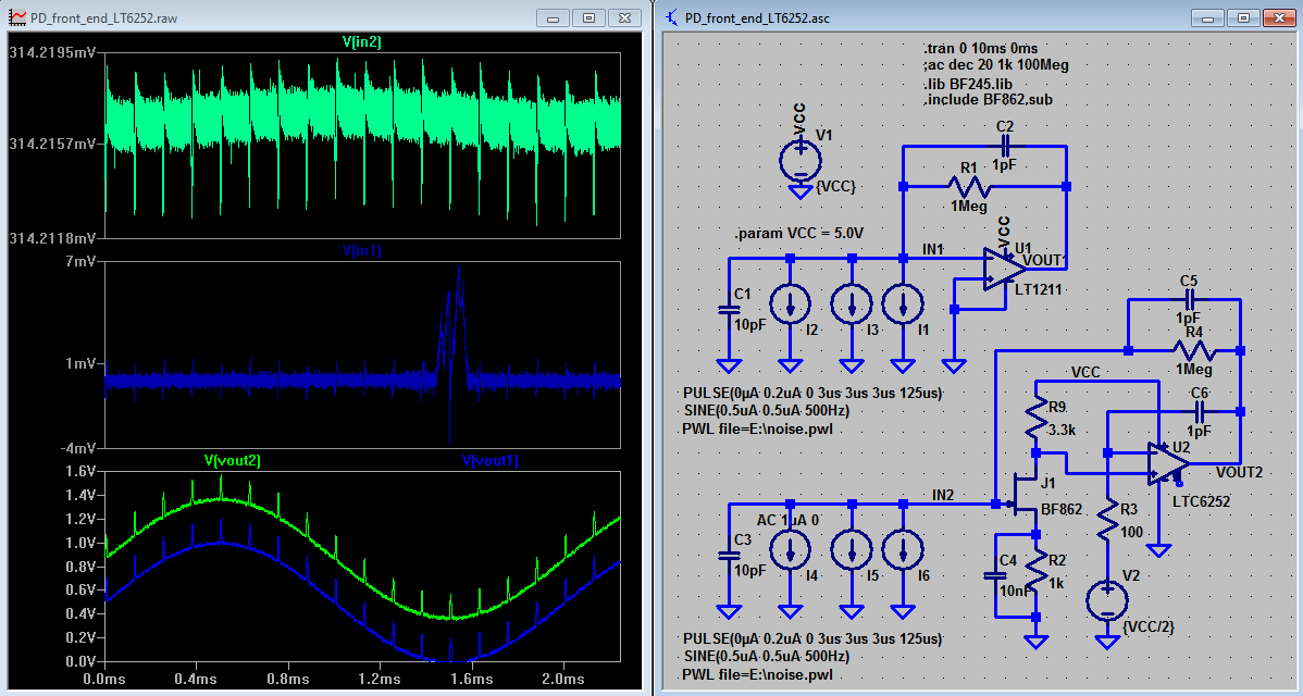
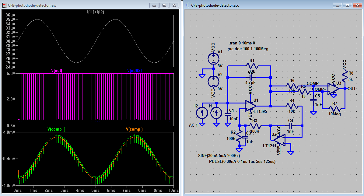
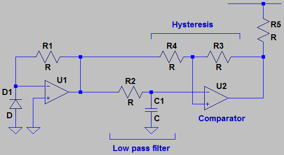
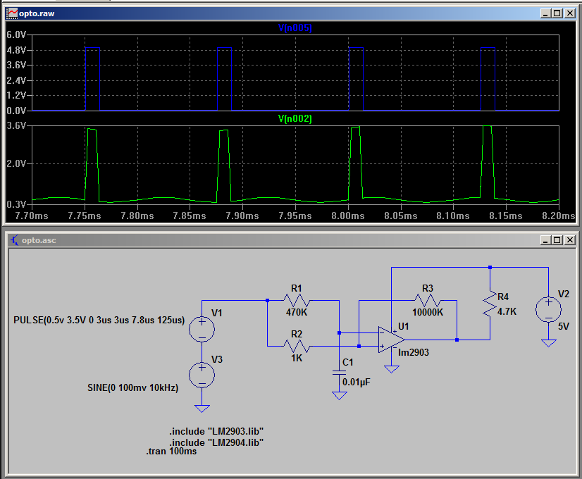
An attempted to build the Hamamatsu S6986 Light Modulation Photo IC from commonly available discrete components.
To make the experience fit your profile, pick a username and tell us what interests you.
We found and based on your interests.
20160920-PD-frontends.zipsketchy photodiode front ends and detector circuit as per discussion (LTSpice simulation files and component models). For practical applications consider CLC425 / AD8000. May not work with photovoltaic mode configuration / may not work without VCC/2 virtual groundZip Archive - 229.86 kB - 09/20/2016 at 10:41 |
|
|
S6986.schSchematicx-kicad-schematic - 14.02 kB - 09/13/2016 at 18:56 |
|
|
S6986.proProjectx-kicad-project - 1.52 kB - 09/13/2016 at 18:56 |
|
From time to time I do some small experiment for this but in general haven't put in a lot for this project sadly. Anyhow....
Ben Krasnows new video does a great job explaining some of the concepts that would go into completing this.
I've added a link to the fantastic Light Modulation IC reference from Hamamatsu (hosted on pobot.org), this is the guide which I'm designing my circuit against.
I've also published the KiCad project and schematic files for my work so far. Bear in mind there is a lot of hand wavyness going on for several reasons.
Firstly I haven't put much consideration into component selection as I'm starting by trying to flush out as much of each stage as I can. So the components in each stage are not likely to be ideal.
Other very vague parts include the LED Driver block, the "D" and "U" signals as I don't have a complete understanding of how these stages work yet.
Create an account to leave a comment. Already have an account? Log In.
Nice! I'm still having trouble finding them available in the US. Just got back from a trip and will resume my hunt.
not sure if that's the real deal or some fake IC, will have to mount the IR camera module to the microscope and check out the die.
Power it up, I hear you say, eh? Too easy ;-)
Where did you end up finding that? I keep searching and cannot find anyone that will ship the US. Did it end up working?
Whoa! So much awesome feedback over the weekend! I've got a bunch of reading to do and great news that new photodiodes arrived Saturday morning. Turns out these cannot handle a ton of soldering/desoldering before before some internal connection breaks down.
What I like to do is to use leaded solder, turn the iron down as far as reasonably possible and since these devices are MSL-3 to -1 they really enjoy the company of a bag of silica gel - so I put them back in the ESD bag and fold over the corner that I cut off. The humidity indicator badge inside tells me that's an OK job for a couple of months.
I've even seen the "popcorning" happen with an 0805 LED under the microscope. Bond wires hate that ;-)
ps.
Sure you want to stick with the BPW34? Smaller photodiodes potentially have lower noise, less capacitance and are better AOI matched to the detected light image. See http://www.vishay.com/photo-detectors/pin-photo/
I'll check out those Vishay parts and get them in my testing. Can you explain AOI? I've tried searching but as it also means Applied Optoelectronic, Inc I'm not getting much useful info.
image area of interest (AOI) or ROI for region. Since you're imaging the laser spot hitting an object at a distance, an image is formed on the photo diode and the AOI is the illuminated part of the focal plane. The magnification of your condensor lens is such that the image formed on the photo diode is quite small, rendering the rest outside the active area a parasitic capacitor and noise source.
The diode area should more or less be the image size plus some margin for parallax and alignment error. There are rather crazy photodiode ICs for CD/DVD pickups that are exemplary devices when it comes to matching optically active area to the focal plane AOI.
Check out http://pdf.datasheetcatalog.com/datasheet/kondenshi/KOD-1017.pdf for some 50x100 µm² photodiodes with on-chip pre-amps. They're actually doing autofocus and tracking servo loops with these and naturally much faster versions exist.
Still waiting for my S6986 though.
ps. Just found an OPT101 in the parts drawe. The datasheet is also something that might interest you www.ti.com/lit/ds/symlink/opt101.pdf
I've been playing around with TIA designs. I know It's lacking some preliminary calculations and noise considerations but here goes
the PD signal is modeled as a 0.5+/-0.5uA sine wave, a 0.2uA pulse with moderate slopes and 0.1uA noise (10 MSa random values -> up to 5 MHz).
I've stumbled across the jFET buffered circuit in the lower right
http://www.linear.com/solutions/1785
which promises to be a low noise TIA with a high frequency boost. While I take it that the circuit works in practice, the simulation is no good with various jFETs without tweaking the operating point (R9 ought to have the same value as R2). Additionally the high bandwidth of the LTC6252 model makes C6 + R3 feedback necessary.
And what's more, the jFET circuit also introduces DC bias that forward biases the photodiode...
Anyone got an idea what's going on here? I'll upload the ltspice files somewhere if required.
@K.C. Lee I've tried to figure out where the RC high pass noise would be coming from. Is it Johnson noise from the bias resistor? Input-referenced noise from the opamp? Please elaborate.
http://www-f9.ijs.si/~margan/Articles/trans_z_amplifier.pdf
Skip to page 15. Most of the high frequency noise would come from voltage noise. (way too much math for me!)
In general, I would try to avoid AC coupled circuits if there are alternatives using low pass filters. AC couple are high pass filters i.e. differentiator. So signals with high frequency components, power supply noise from digital circuits tends to be emphasised.
If you have signals referenced to ground for analog circuits that runs on a single supply, AC coupling would mean that part of that signal will be below ground. Having to bias stuff to half rail just add complexity.
Bare in mind that the circuit detects the presence of the IR signal - all you need is a '0' or '1' for a presence. You don't need to worry about error rates, so signal processing can be as ugly as it can be while using as simple design as possible.
I keep looking at the DC-servo idea, I know orthogonal to the low-passed threshold, but the background DC levels alone will make detection with a fixed-gain TIA difficult. For example, the background illumination levels in an environment with windows can vary over six orders of magnitude or more just from natural light (moonlit to sunlit). Even IR filtering doesn't help much here because natural lighting is loaded with IR. I just surveyed my house with an IR-filtered BPW34, and although LED lighting doesn't emit significant amounts, incandescent obviously is loaded and even fluorescent lamps emit some. Unless you expect the sensor to be in controlled lighting conditions, it might make sense to design for a wide range of ambient levels.
On the other side there is the fixed gain TIA illustrated in the datasheet, a moderately small area photodiode and google comes up with a telecentric lens assembly in a practical implementation. The datasheet btw. only mentions applications which are suspiciously controlled regarding their environment. Hmm.
in http://users.ox.ac.uk/~atdgroup/technicalnotes/Getting the best out of photodiode detectors.pdf p.6
there is a neat little circuit showing a DC cancellation loop implemented around a current-feedback amplifier:
These devices (I have yet to fully wrap my head around them) are notoriously quoted for their high bandwidth and high current noise which in combination with most designers not being overly familiar with them explains why they are rarely used.
After some thinking there's hardly any other way to compensate the diode current over many orders of magnitude than to directly feed the current summing point with the bias current. While (bipolar) current mirrors might be the obvious choice they can be expected to be significant sources of noise and only super beta types could be suitable. So we'd at least have to pick an ultra low noise CFA and then the DC error current is coming from the inverting input?
( regarding stability, Cf might be suspicious but it appears to be there for some cancellation of a pole due to the diode capacitance, see http://www.analog.com/library/analogdialogue/archives/47-07/current_feedback.pdf )
I still can't help but acknowledge the benefits of the simple circuit as suggested by K.C. Lee - maybe it's just a matter of running into saturation at 10000 lx of incandescent background illumination and the small signal AC detector will do the rest.
ps. I couldn't resist. low frequency rejection up to 500 Hz is quite solid (still 3 orders of magnitude) but via the positive feedback and the high pass distorted peak waveform there's a lower limit at around 20nA photo current. Not quite what you'd expect when compared to LIA measurements but then again you don't have to filter a mixed output over hundreds of cycles.
coming to speak of it... Hamamatsu quotes some 1 kHz response. At 125 kHz for the pulse rep. rate that actually would speak in favor of LIA and some hundred cycles. Strange...
There is only so much servoing you can do as ultimately the offset can be at most be from output of the feedback amplifier vs something with large orders of magnitudes.
May be the amplifier needs to be non-linear like a log amplifier for what you are thinking.
Or that your light source has enough SNR over the background light even in the brightest background. If the background is dark you are laughing. i.e. you light source is much brighter than the ambient.
Years ago (c. 2009) I made a receiver for a structured-light registration system that used a log-type photodiode amp. I just connected a diode instead of the feedback resistor in the TIA (actually I used the BE junction of a 2N3904 as I recall) to get a log response. The thing varied wildly with temperature, but the threshold was derived similar to K.C.'s idea, so it worked with a very wide range of signals. I had full control of ambient lighting in that situation, so it wasn't the same problem. I simply made sure the lights were off.
The issue with a log amp with a DC offset is that on the high end, your signal gets squashed since log(x+e) ~ log(x) for small e.
The servo loop (as shown with the CFA) seems to work over the entire diode current range which is quite nice (30nA pulses over 50uA - you can barely see the the small dents in the gray current waveform). I'd prefer a higher order low pass for the servo loop, seems kinda sluggish right now. Performance might even be better when the whole circuit is run from a single supply and the diode is reverse biased.
Still we're nowhere near a simple solution with my suggestion.
@K.C. Lee FWIW I'll be bouncing a 650nm laser off a mirror (if needed) as my detection light source.
As I'm learning and trying to get better at SPICE simulations I would love to see the files contributed!
Am I correct in thinking the power sources I1,I2,I3 / I4,I5,I5 are to model the pulse of the photodiode and background noise? How does the sine fit into that?
correct. The sine represents line hum or one of its harmonics. You can also make it the fundamental of a CFL.
I see you like you background white, I personally prefer mine black, but I do a lot of work at night and it saves my eyes.
Your U3, high pass filter and schmitt trigger aren't going to work. High pass RC (AC coupling) are going to be noisy in real life. :P Schmitt trigger is wrong as there isn't anything to bias the input. U3 isn't going to give you a reference. Too many things wrong with the analog front end.
You are better off using a low pass RC from the Transimpedance amplifier as a reference and feed that to a comparator with a small amount of hysteresis to square off the signal. The schmitt trigger should be applied after the comparator and not before. (The hysteresis should do a reasonably job already if you pick the right values.)
Might want to use something better than 741 and LM358. :P They are 40 years or so old parts and there are better ones made since.
There's an interesting auto-threshold circuit in one of the Jim Williams App Notes:
https://cds.linear.com/docs/en/application-note/an47fa.pdf?page=43
(on page 44 in case the page link doesn't work).
The low pass filter automatically keep track of the DC offset from the ambient light levels. So only fast changes in the light inputs shows up at the output. You can play with the bandwidth a bit to remove AC noise from old light bulb. CF lighting is too high a frequency and could be removed by low pass filtering the input before the comparator.
It works like AC coupling but without the noisiness associated with a high pass filter as the threshold level is bandwidth limited.
I'd actually go for just a high pass filter (I'm assuming you intended the low pass filtered signal to presented to the other amplifier input for subtraction to have baseline restoration). Not only is the high pass character hinted in the S6986 block diagram but if you're actually working with low duty cycle light pulses the information is spread across a ladder of harmonics of power inversely proportional to the frequency.
Then of course we'd want to cut off at some frequency where the integrated spectral noise outweighs the information in that same spectral region. Maybe that threshold is just after the fundamental frequency (it most likely is for 50% duty cycle) - but as pulses are narrowed, power gets distributed across higher harmonics.
The cool thing is that we get the low pass filter that causes the received signal to be band pass filtered for free. The photodiode capacitance does that for us.
There's an excellent and intimidatinly thorough article by Hobbs, "Photodiode Front Ends - The REALStory" that covers bandwidth and noise of photodiode front ends.
diliev.com/Home/materiali/OLUP/frontends-Photodiods.pdf
(it's actually a rendering from a whole chapter of a book)
High pass filter get you lots of noise as they are not band limited. That's why I present this as an alternative to AC coupling. The pulse would still show up with the low pass as they are higher than the average ambient level.
Having the low pass in the threshold path doesn't mean the comparator is ignoring high frequency signals as the input side to the comparator is still full bandwidth.
Consider bandpass filter if you have an aversion to low pass.
Counter AC coupling on low duty cycle signal with this: http://www.sigcon.com/Pubs/news/4_15.htm
>AC coupling works successfully only with binary signals that have equal numbers of ones and zeroes. Examples of such signals include a 50 percent duty-cycle clocks, Manchester-coded data signals, and ANSI Fiber-Channel 8B10B signals. Many other data codes also enforce equal numbers of ones and zeroes. The property of having equal numbers of ones and zeros is called the property of DC balance.
The low pass on the threshold provide a DC path, so it can deal with low duty cycle.
http://www.ni.com/white-paper/14753/en/
Look at the AC coupled waveform.
Apologies for not following along with your concept. Here's what I had in mind:
I've had a brief look at the technical information sheet (I'm working over the weekend and use this as a bit of a distraction). If I'm not mistaken the device operates at 8 kHz give or take a factor of two (bloody uncalibrated on-chip resistors) and a duty cycle of 1/16. The approximate shape of "PD current" suggests we could fit a whole sine wave in there with that slope, giving us 125kHz bandwidth after a TIA which could as well be providing that "low pass" cut-off of the input signal to that bandwidth. Unlike shown in the drawing I'd grab that LPF input from Vout and put the blocking capacitor between the TIA and the buffer amplifier that follows, providing the required DC rejection without further introduction of noise. The amplifier would be low noise and low gain with limited bandwidth.
Yes, you can DC servo the transimpedance amplifier, but that's not what I said. Might want to read carefully to my intentions before you make any more assumptions? (2 wrong ones so far)
Implementation:
>You are better off using a low pass RC from the Transimpedance amplifier as a reference and feed that to a comparator with a small amount of hysteresis to square off the signal.
My reasoning:
>It works like AC coupling but without the noisiness associated with a high pass filter as the threshold level is bandwidth limited.
R3, R4 are to provide a tiny bit of positive feedback for hysteresis (tens of mV) just to clean up the signal. Otherwise the SIGNAL path is clear of passives. i.e. No DC blocking caps which is the problem I am addressing.
Comparator is open drain/collector, so need the pull up.
FYI. I ran a simulation in LTSpice with 8kHz, 1/16 duty cycle, added DC offset of 0.5V, 3us rise/fall time 100mV of 10kHz signal injected (green track). Top trace (blue) is the output.
Cool project! As Ted already states the device function and threshold levels achieved indicate the basic design is a lock-in amplifier. While my first thought was something along the lines of AD630, looking at the "Comparator", "Signal Processing Circuit" and "Oscillator" maybe a HEF4046 can be coaxed into doing what we want.
But then again they are talking about pulse detection and synchronous background rejection as if the integration times would be strongly weighted and only short pulses of light would actually be used while the off times in between them would be averaged out.
The latter reminds me of IrDA SIR encoders/decoders.
Looking forward to where this is going!
It looks like a lock-in amplifier. I've always thought that circuits like this should use a LFSR to modulate the LED with pseudo-noise to prevent interference from/to other sensors, especially in a robot context.
Neat, I wasn't familiar with a LFSR. Ran across an excerpt in a book and a simple schematic I mocked up in Falstad. http://www.falstad.com/circuit/circuitjs.html?cct=$+1+0.000005+10.20027730826997+50+5+43 155+128+160+176+160+4+5 155+304+160+336+160+0+5 155+480+160+496+160+0+0 R+80+304+80+352+1+2+100+2.5+2.5+0+0.5 w+80+304+80+192+0 w+80+192+128+192+0 w+80+3...
Yep, that's the idea. At lower bit rates, a software version is typically cheaper, although not always as much fun, but if you've got a microcontroller in there you can have it for free.
What about handling everything except maybe the front-end amplifier and mixer with a microcontroller? You can even get the op-amps and comparators built-in these days, although I'm not sure op-amps built in to uC's would be up to the task.
As this is an exercise in using discrete components I won't be using a micro for anything.
BTW I used the LT1043 to build a lock-in amplifier. http://cds.linear.com/docs/en/application-note/an03f.pdf (Page 4)
It could be done with 74xx MUX and gates.
You basically have an oscillator that drive both the LED and control the gain of an amplifier to either +1 or -1 (synchronous demodulator). Low pass filter the output and that's it.
The +/- 1 gain amplifier can probably be replaced with a 74xx86 xor gate.
I have looked at the LT1043 about a dozen times over the years, but never ended up using one. Interesting part.
I think you're probably better off doing the mixing before thresholding - use +/-1 op-amps followed by 74HC4066 switches. Low-pass to remove the 2x frequency component, then threshold.
LT1043 is good for precision analog circuits as they are carefully about avoiding charge injection during switching. I had to use it as one point as the sensor requires AC excitation. It worked very well.
In this type of on/off detection application, you can get away with just about any type of cheap MUX.
I still think the XOR would work as the synchronous demodulator - replacing the MUX and opamp. It is similar to the XOR phase detector in a PLL. With a low pass filter at the output and some fixed threshold, that's as simple as it can get.
Maybe @helge is on to something with the HEF4046 - just make it a 74HC4046 (to keep the 74xx theme), and you have an oscillator and your choice of phase detectors built-in; no need to actually close the PLL loop. Use a transimpedance amp on the front end and comparator after the filtered phase detector output, and maybe that's it.
Become a member to follow this project and never miss any updates
By using our website and services, you expressly agree to the placement of our performance, functionality, and advertising cookies. Learn More
know your enemy