U.S. Water Rockets
-
A Really Cool Part Fan
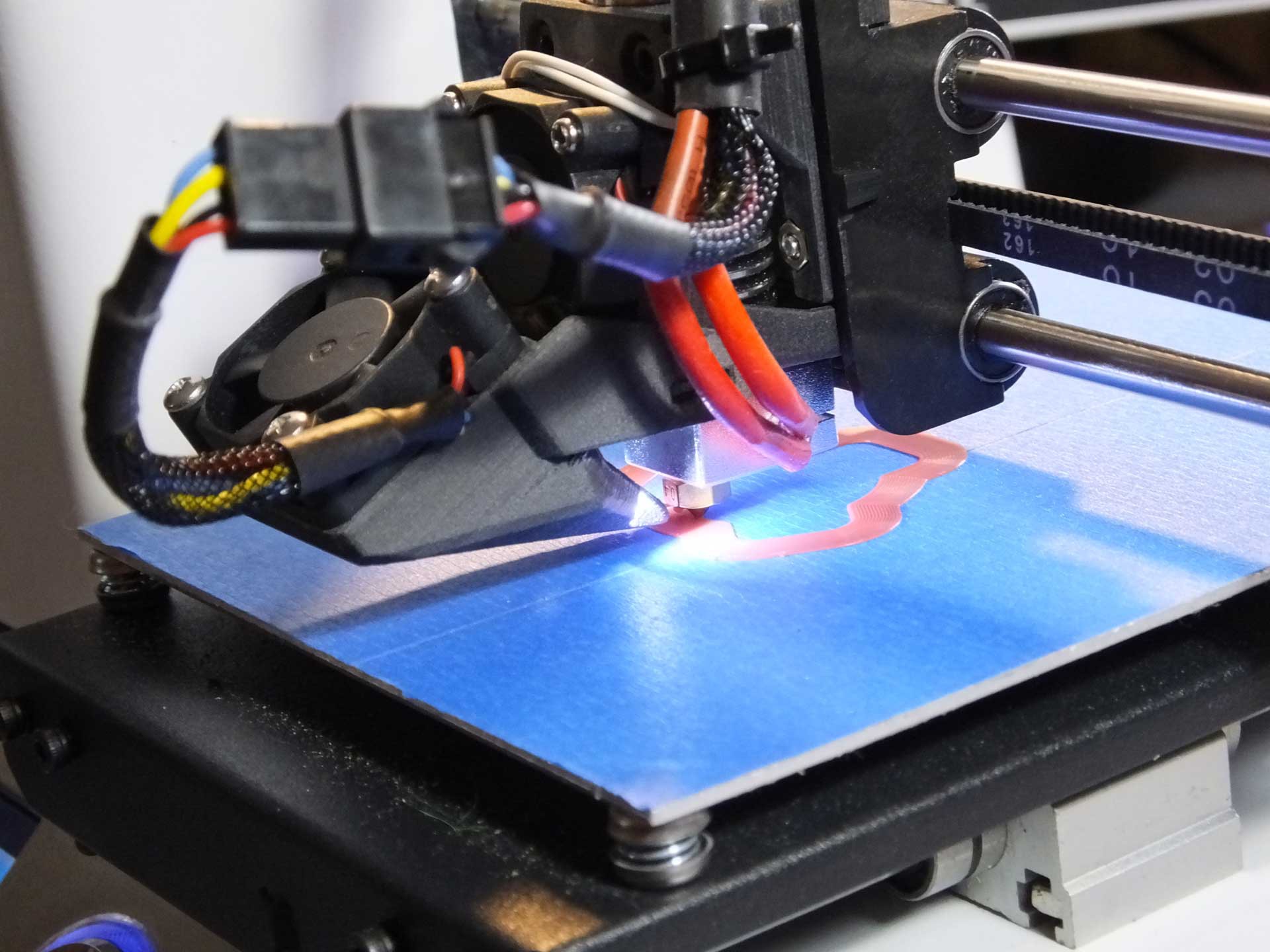
10/26/2016 at 01:51 • 2 commentsThe next improvement we are making to our Monoprice Select Mini is the addition of a Part Cooling Fan, which is a separate fan with directed air flow that is controlled by the Fan Output of the control board.
This means we had to rewire the fan attached to the E3Dv6 Fan, so that it will run when the printer is switched on, and take the existing fan wires, and connect them to the Part Cooling Fan. This way, fan control options in the slicer will be able to change the fan speed of the part cooling fan and turn it off for better bed adhesion without causing heat creep leading to jams in or above the heat break.
To make the fan attachment even cooler, a pair of 3mm White LEDs were built into the air duct to illuminate the print area under the nozzle.
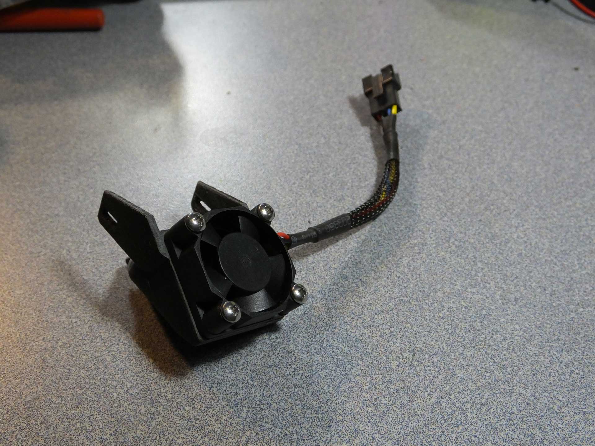
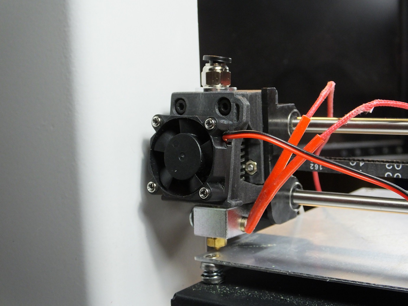
 This is that the Part Cooling Fan looks like when it is removed from the E3DV6 Mount. Notice that it has a JST style connector so that I can swap in different fans and LED lights in the future as I design new styles.
The outlet of this nozzle directs all of the air flow directly on the extruded plastic that has just exited the nozzle. This is intended for improving overhangs and bridges. You can also see the LEDs that illuminate the print beside the outlet.
This is that the Part Cooling Fan looks like when it is removed from the E3DV6 Mount. Notice that it has a JST style connector so that I can swap in different fans and LED lights in the future as I design new styles.
The outlet of this nozzle directs all of the air flow directly on the extruded plastic that has just exited the nozzle. This is intended for improving overhangs and bridges. You can also see the LEDs that illuminate the print beside the outlet.
Here is a very short video clip of the Zero Offset E3Dv6 Mount and LED Part Cooling Fan in action.
This modification was hard to put a price on because we had most of the parts laying around. The fan came from the E3Dv6 and the JST connectors were in an assortment we had, and the wire was salvaged from an old PC. Even if these parts were sourced new, the total would still likely be under $5.00US.
-
Zero Offset E3Dv6 Clone Hot End Mount
09/23/2016 at 17:15 • 8 commentsWhen the Monoprice Select Mini was first featured on HaD, the recommended first modification to perform was to swap out the hot end for an E3Dv6, using a 3D Printed mount. Before I even had the printer, I had ordered a $6.00 clone from Amazon, with a 0.25mm nozzle, anticipating that I would need the new hot end to be able to use commonly available nozzles in various sizes and materials. At the time, I was not aware that the stock hot end could work with common nozzles. I could easily swap out the stock nozzle and save some money, but after thinking about it a bit more I decided that I really wanted to have a separate hot end cooling fan and hot end layer fan, for better control over bridging and overhangs.
I looked at the available fan mounts that had been published when I received my MPSM, and I was not excited because they offset the nozzle quite a bit from stock, they pushed the nozzle down in the Z axis, and forward in the Y axis. This causes the nozzle tip to move almost all the way off the font of the build platform, and requires that the leveling screws get cranked way down to clear the nozzle.
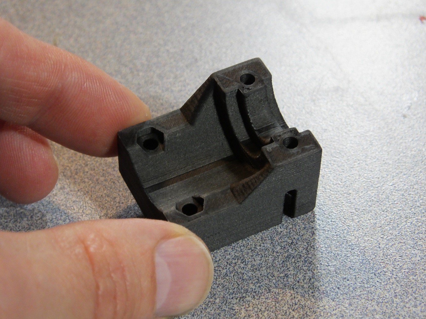
I didn't like losing build volume, due to the offset, so I started work on my own adapter design that retained the position of the nozzle as much as possible. Once I found the correct position for the nozzle, it was apparent that the strength of the screw mounting would be compromised because the space available was very thin. But I realized that I could extend the bracket inside the hollow cavity in the carriage, and use the walls and bosses in the cavity for strength. The screws would merely hold the bracket without experiencing much force.
With the printer torn down to this level, I noticed the way the X-Axis belt was fastened, and it gave me an idea. I made a similar tab on the rear of my hot end adapter, so that the belt tension would hold it in place instead of the screws, which I would eliminate.
Ultimately, when I tested this design, the flexibility of the belt did not hold the bracket as firmly as I wanted, so I put the screw mounts back into the design. However, I noticed that the belt grip on the back actually acted like a belt tensioner, by removing slack from the belt.
The final design includes both the belt tensioning feature and the screw bosses, and holds the mount very securely.
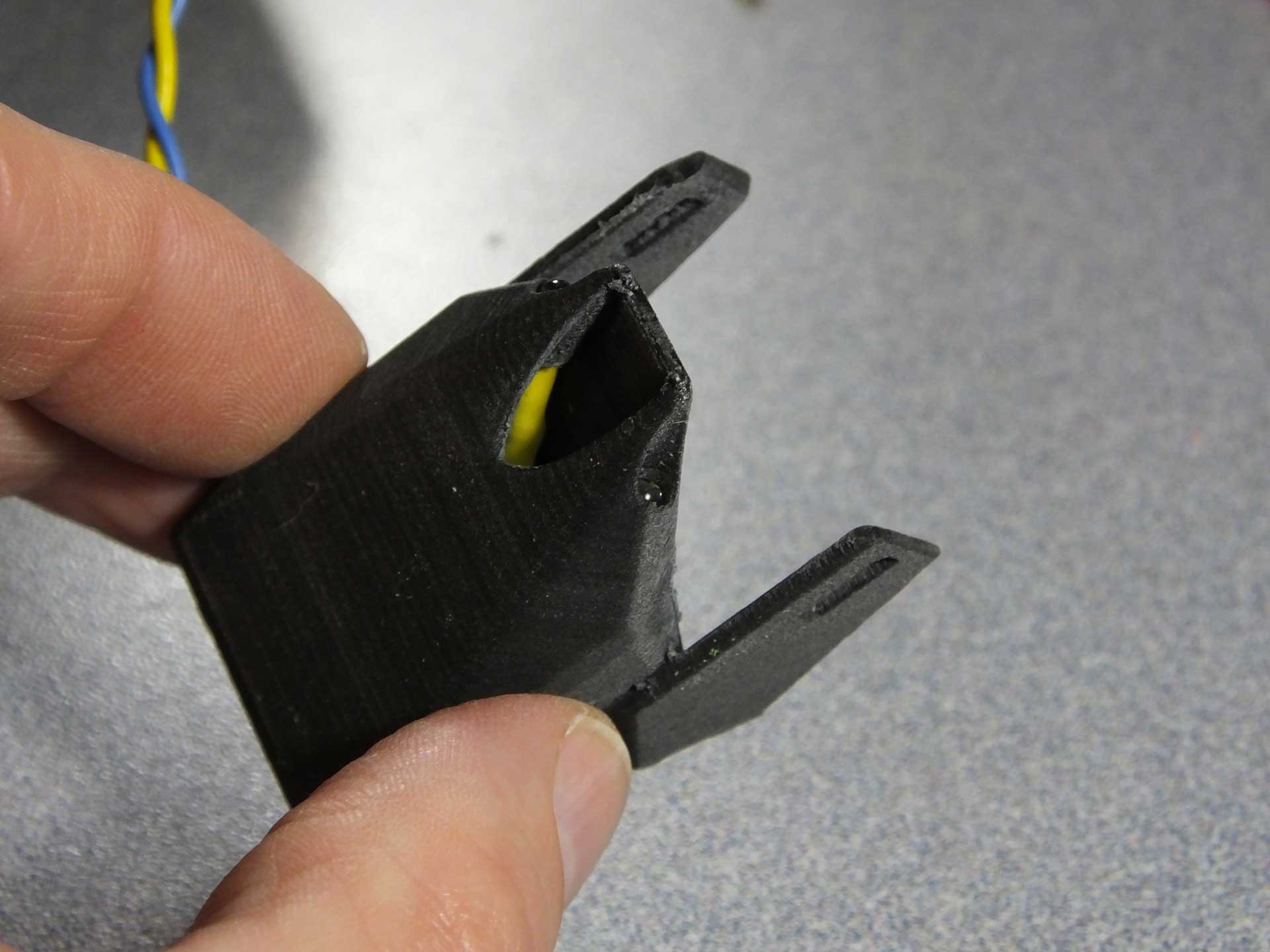
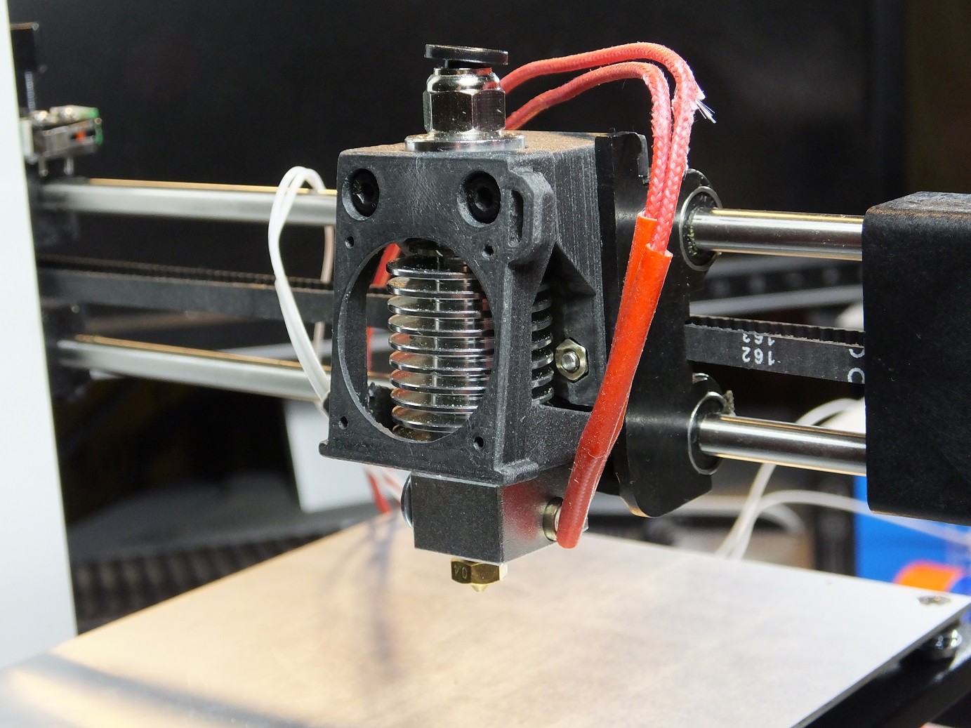
With the mount installed, I then created a fan shroud which would direct cooling air through the heat sink on the E3Dv6 Clone. This shroud design would double as the mounting clamp for the hot end, would have to be designed to maximize the cooling, and direct the exhaust air away from the print, to help prevent ABS warping. A layer fan accessory would attach to this shroud to provide controlled cooling for bridges and where needed.
The new mount shown here takes a 30mm fan, from the E3Dv6 clone. The stock heat sink and fan had no problems with filament temperatures up to 270C, so the E3Dv6 clone with the superior heat sink and larger air evacuation ports in the shroud should work just as well. Using a larger fan seems like an unnecessary change at this time.
The hot end fan was installed on the shroud, and looks like it will work great. There is still quite a bit of wiring to be done to make this all work, so I have not been able to test it yet. The internals of the printer are still spread out over the table beside the printer.
This is the new "Home" position of the new hot end nozzle tip, using this bracket. I estimated the position based on where the limit switches engaged. The bed didn't require any adjustments, and the Y-Axis seems very close to where I recall it was before I began. I should have taken some photos for reference, but I forgot.
Next up is some wiring and electrical modifications!
-
Adding 3D Printed Z-Axis Rod Stabilizers
09/16/2016 at 19:04 • 6 commentsGet the latest version of this part on our Thingiverse Page right here: http://www.thingiverse.com/thing:1775502
While disassembling the printer to add some accessory wiring (to be explained in a future project log) we observed that the Z-Axis linear rods were somewhat loose. After inspecting the assembly, it was apparent that the 4 brackets which hold the rods in place at the top and bottom of the printer have a hole which each rod seats in which is slightly oversize. This is likely to insure that variations in part tolerances will not prevent the parts from fitting together.
The downside to the oversize bracket holes is that it allows for some play in the rods, which is magnified the farther along the X axis the hot end moves out. The gantry acting as a lever multiples any play in the rods. This issue can lead to defects in prints. Further compromising the design is the discovery that the rails are cut slightly shorter than the distance between the brackets, This is also obviously done so that the rails could be cut with loose tolerances and would always fit in the printer, but the downside of this approach is the rails can also move up and down in their brackets, as they float freely in the brackets with a small gap on the top and bottom. The combination of loose tolerances in the brackets and rods also contributes to making the printer noisy, as these loose rails tend to rattle under certain conditions.
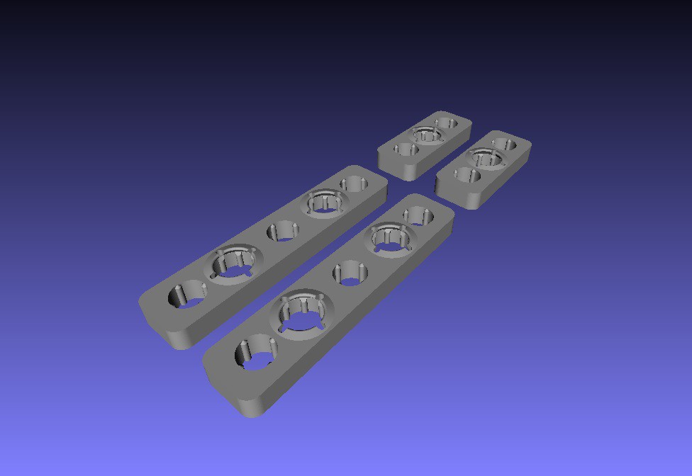
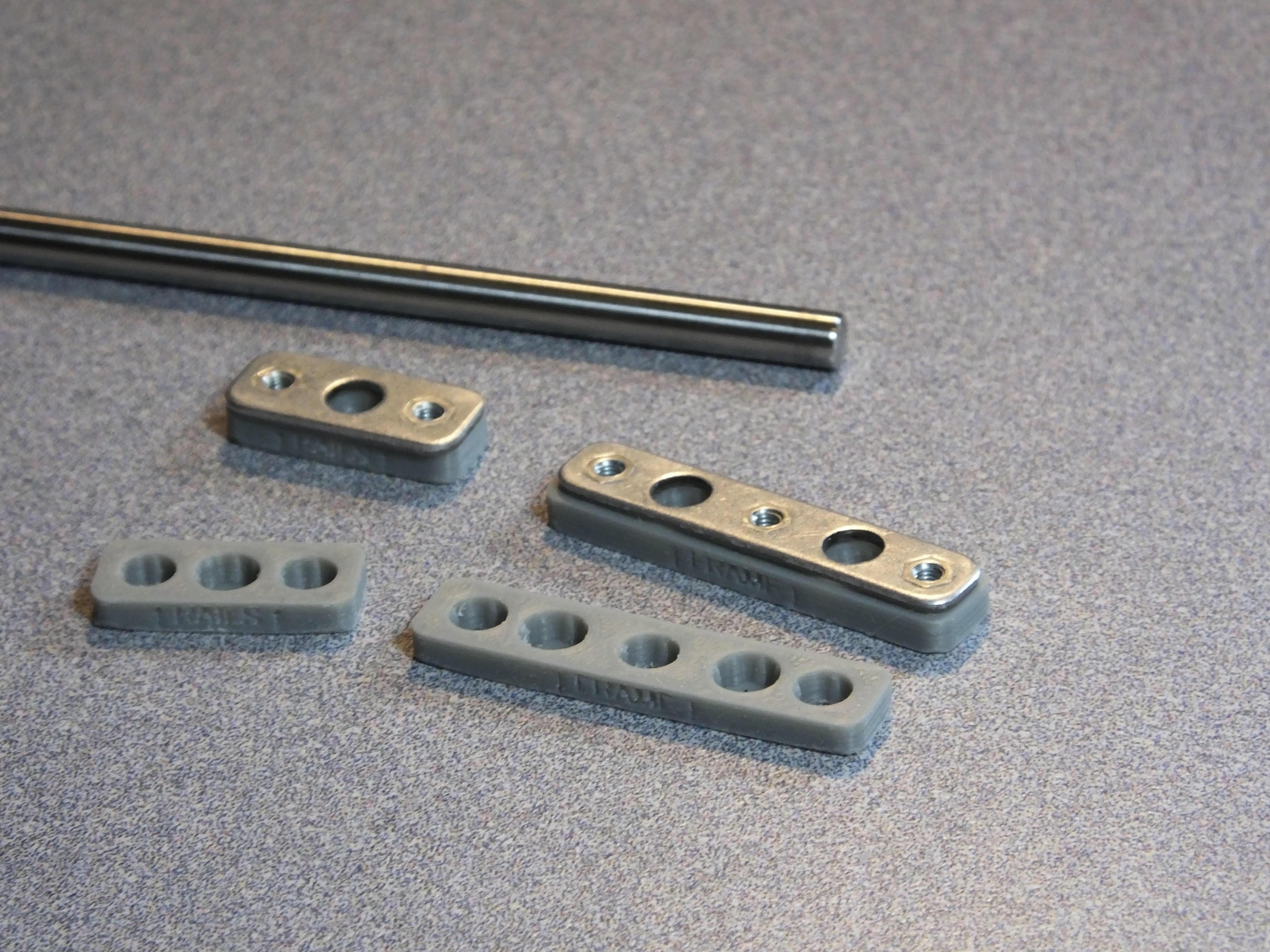
Our solution was to print some stabilizers which would fit under the existing brackets and through the inclusion of a tapered hole for the rods, the rods would be centered in the stabilizers and held firmly in place. These stabilizers were designed and printed but upon testing we discovered that variations in the lengths of the rods and possibly in the bends of the sheet metal enclosure would lead to different length of rod protruding into the tapered seat, so longer rods would push farther in than shorter rods. This causes the shorter rods to be held less firmly than the longer rods, so the stabilizing was not uniform depending on rod length.
Our second design solved the issues we discovered. The improved stabilizers eliminate the tapered seat for the rods and have a feature on the outboard side of the stabilizer which is designed to flex outward when the rod is inserted. This feature is tapered in a way that causes it to compress very tightly around the rod when the clamp is installed.
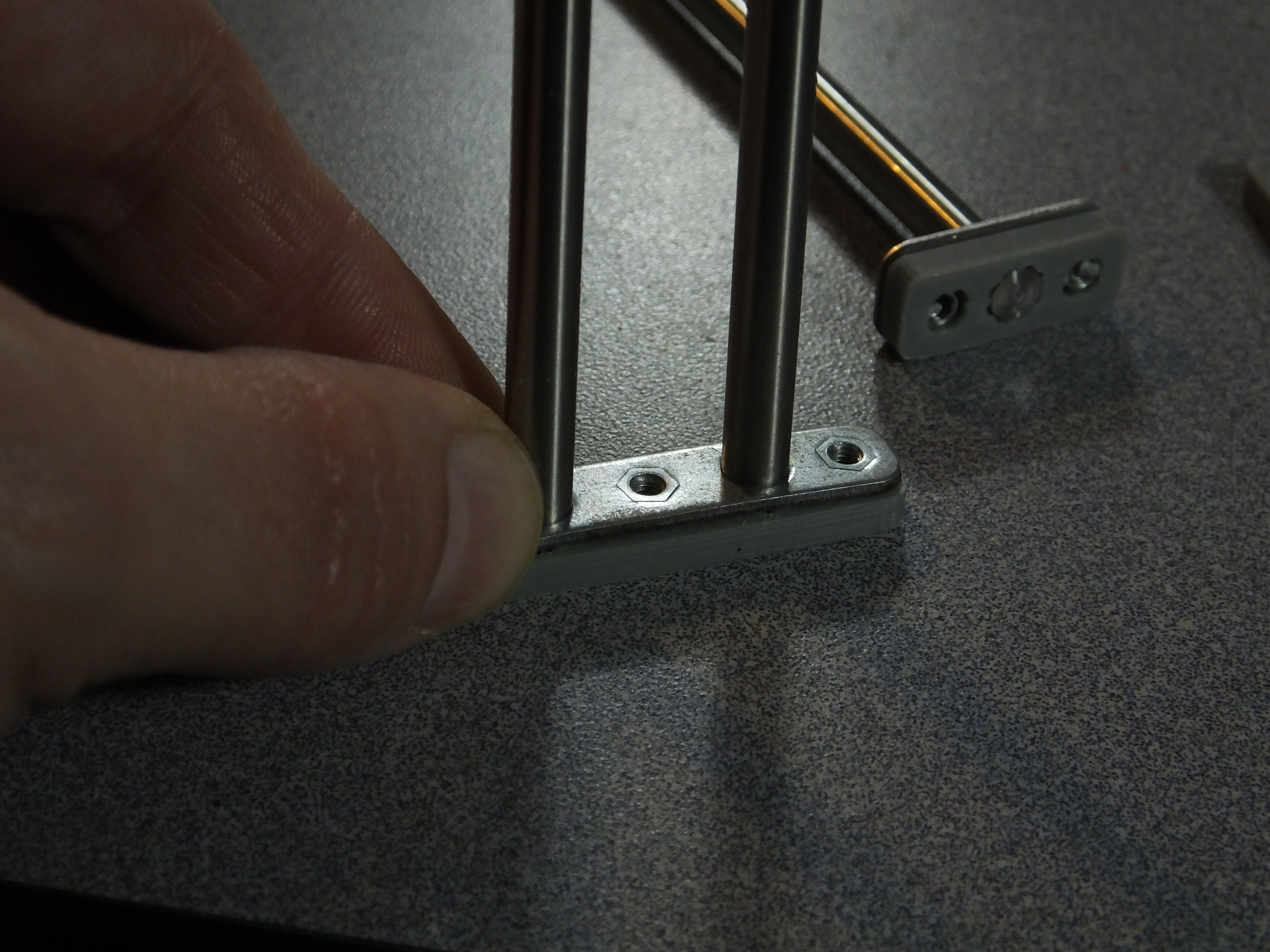
To install the rod stabilizers, we had to remove the covers from the bottom of the printer and rear of the tower. Then we removed the M3 Cap screws which hold the rail brackets to the top and bottom of the tower. There are two brackets with 3 screws and two brackets with 2 screws.
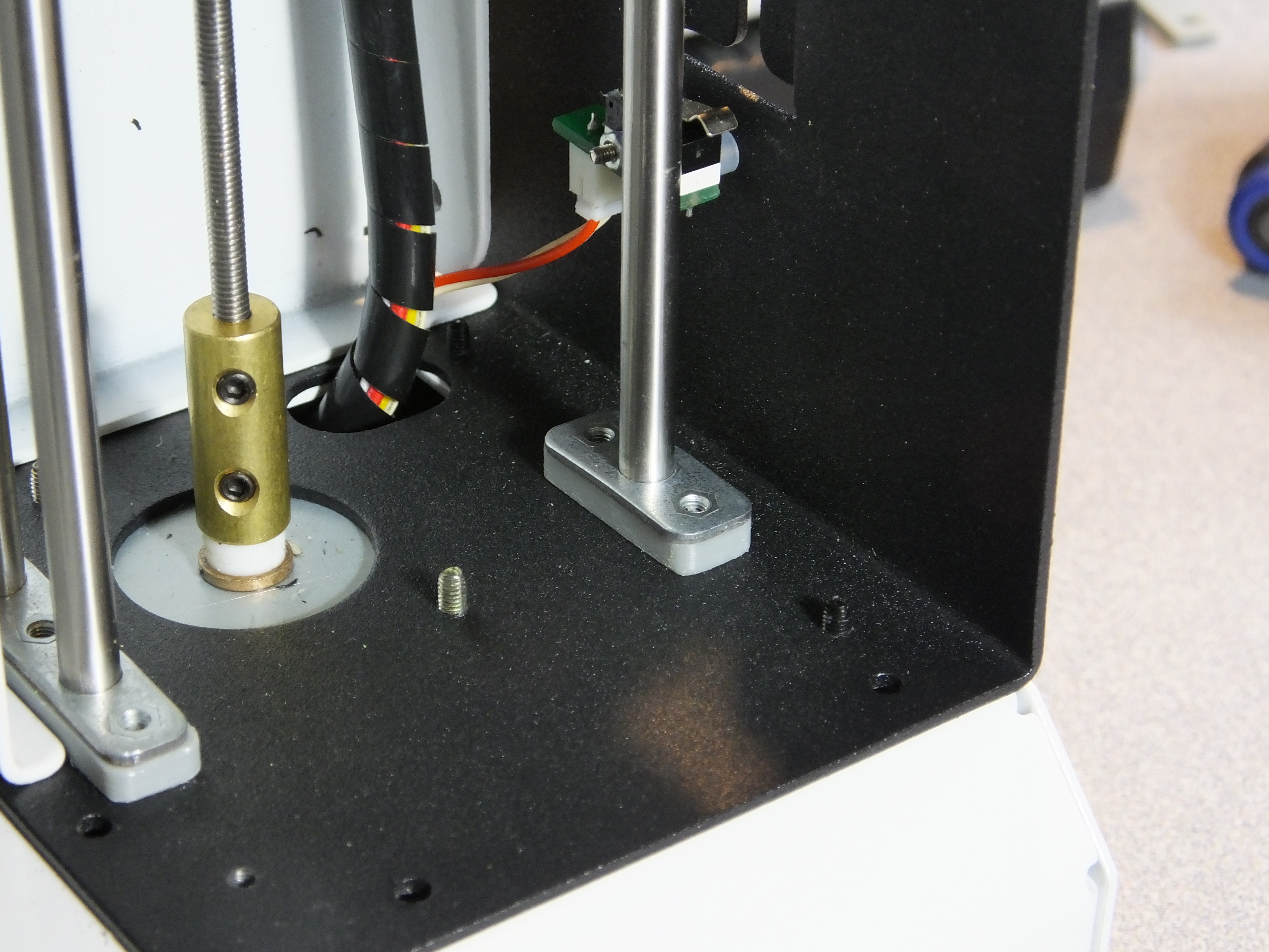
We also removed the Z-Axis stepper motor by loosening the grub screws holding it to the threaded rod for the Z-Axis, and the two screws holding the stepper motor in place. This let us slide the gantry assembly out of the rear of the printer and slide the rails off the brackets.
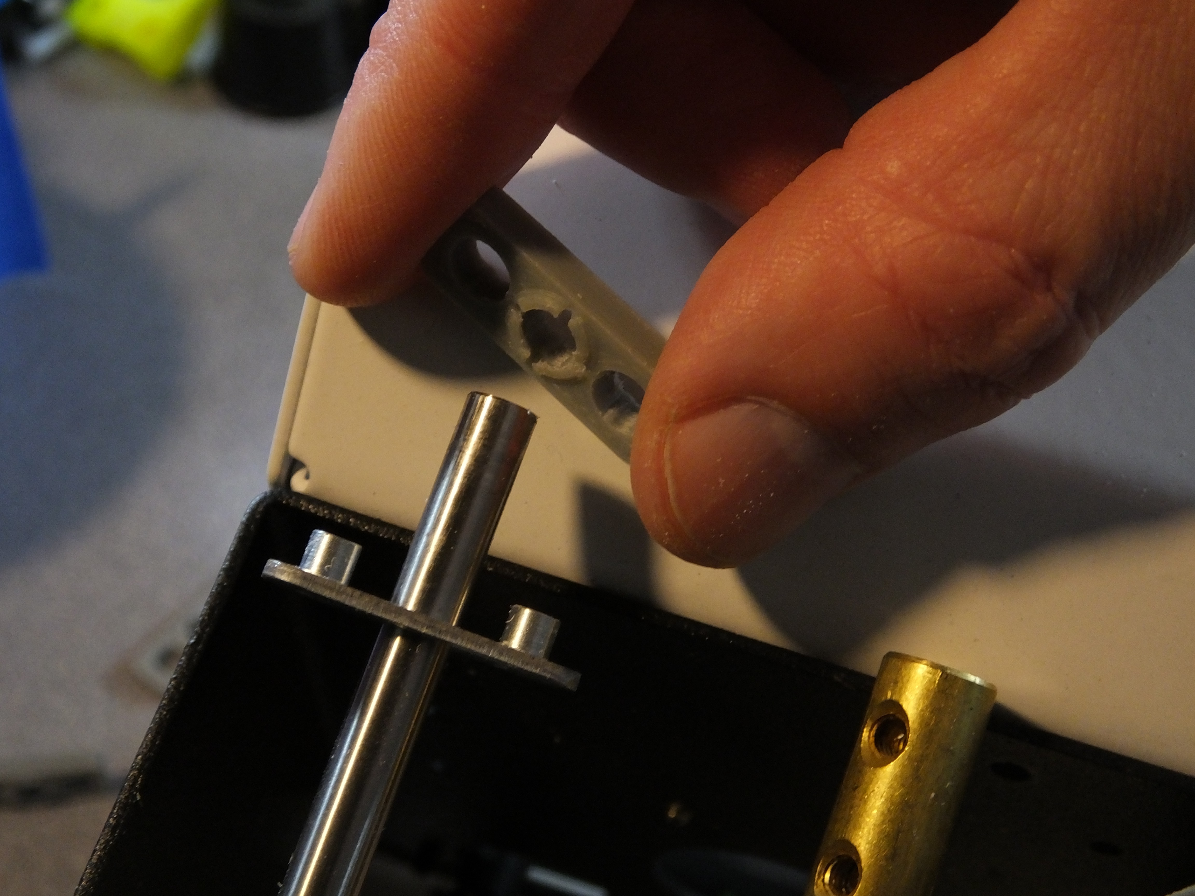
Installing the printed stabilizers was very straightforward. The first step is to slide one of the brackets over the rod. The next step is to push the rod into the stabilizer through one of the rod openings. The rod should be hard to press into the hole, as it has to spread the opening to pass through. This is normal. The stabilizers only go on one way, so make sure you are pushing them on with the clamping feature facing the bracket. The third step is to realize you forgot to put the bracket on and so you have to remove the stabilizer and then start over with the bracket.
With the stabilizers in place, you can slide the brackets down and in place over them. The brackets have tight tolerances with the holes in the stabilizers, so make sure toy press them straight on. They should snap in place against the brackets with a little effort.
Now, you can reinstall the assembly in the printer tower. When you tighten the cap screws on the brackets, the clamp features on the stabilizers under the brackets will constrict tightly around the rods and secure them from moving.
You can now reassemble the rest of the printer and you should see less play in the tower!
Congratulations! You've just made a huge improvement to the Z-Axis stability for a few pennies of filament and a little of your time!
-
Replacing the wimpy Belt Tensioners to improve positioning accuracy
09/16/2016 at 17:46 • 0 commentsThe very first improvement we could make to the MPSM which was fairly obvious right off the bat was that the stock bent tensioning system used spring clips, which have a relatively low spring force, and could easily flex during fast translations, leading to overshooting or undershooting artifacts in the print.
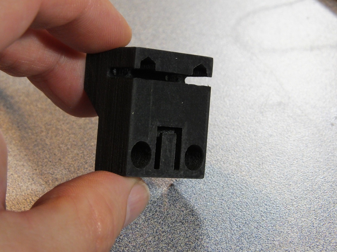
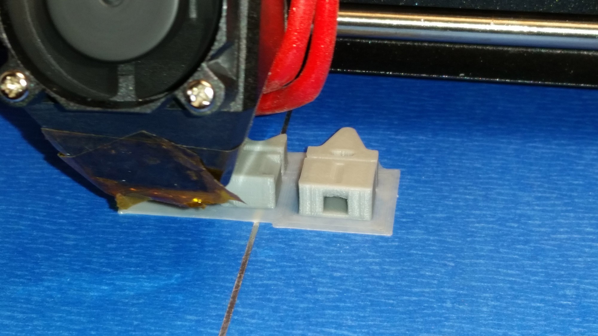
Our solution to this issue was to create and print some new rigid Belt Tensioning Clips for the X and Y axis belts. We whipped up a prototype and printed it on the MPSM itself.
You can find the belt tensioner files on our thingiverse page at: http://www.thingiverse.com/USWaterRockets
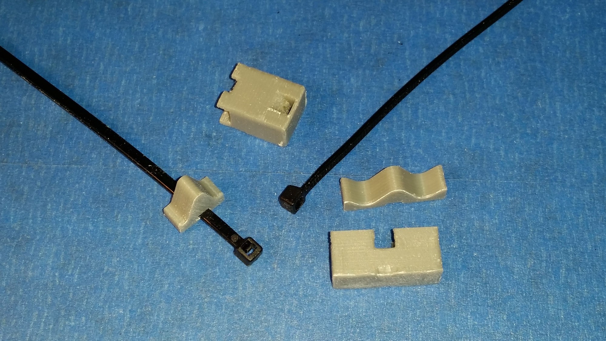
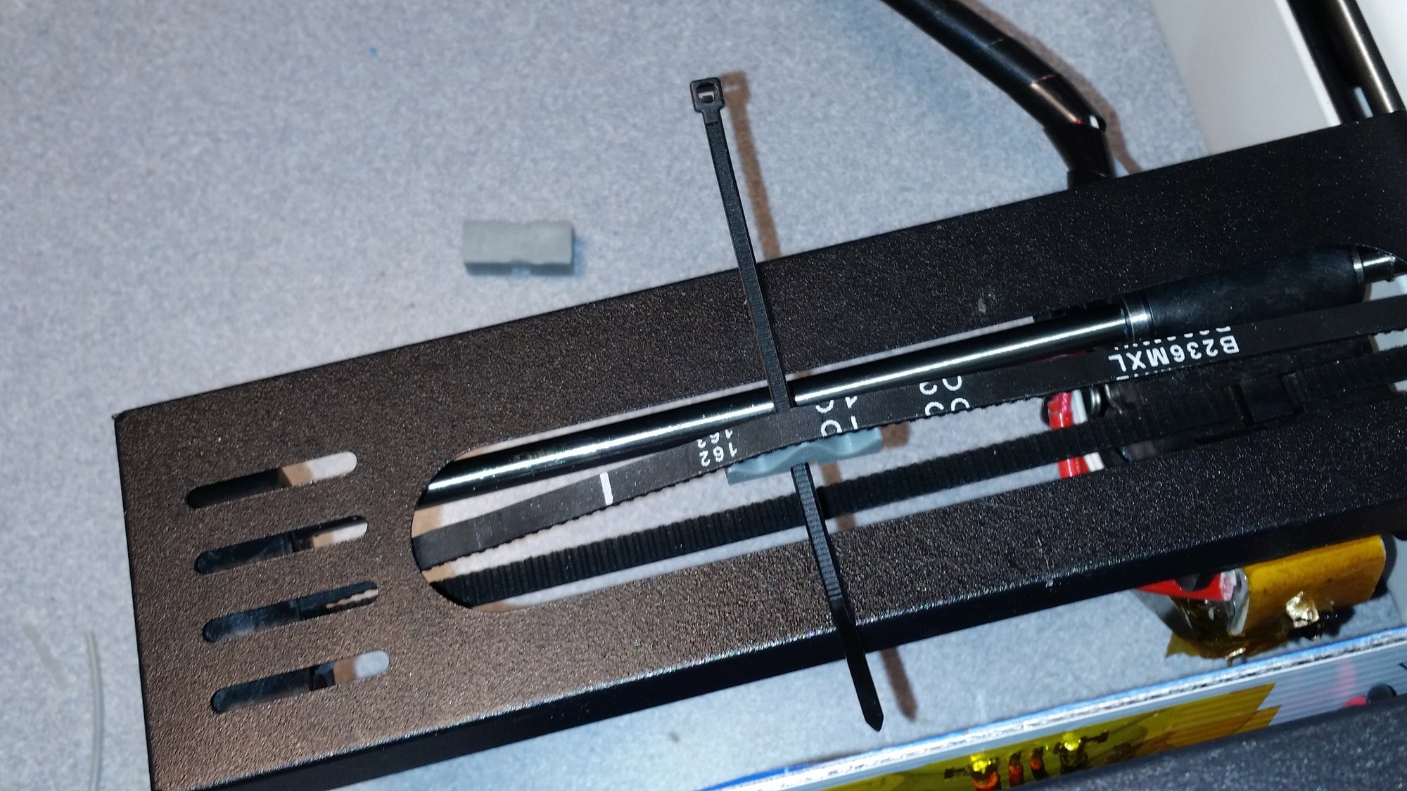
After printing the new tensioners, the old ones were removed and the new ones were installed in their place. The new tensioners use a cable tie to compress two halves together to deflect the belt and provide tension. Tension is adjusted by tightening the cable tie. Note that the tensioners differ for the two belts. This is because the space available to place the tensioners in each axis was not the same, so we had to get creative with the shape of the tensioners.
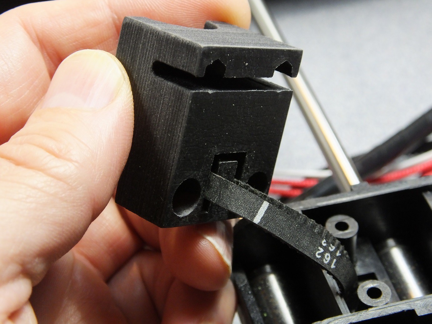
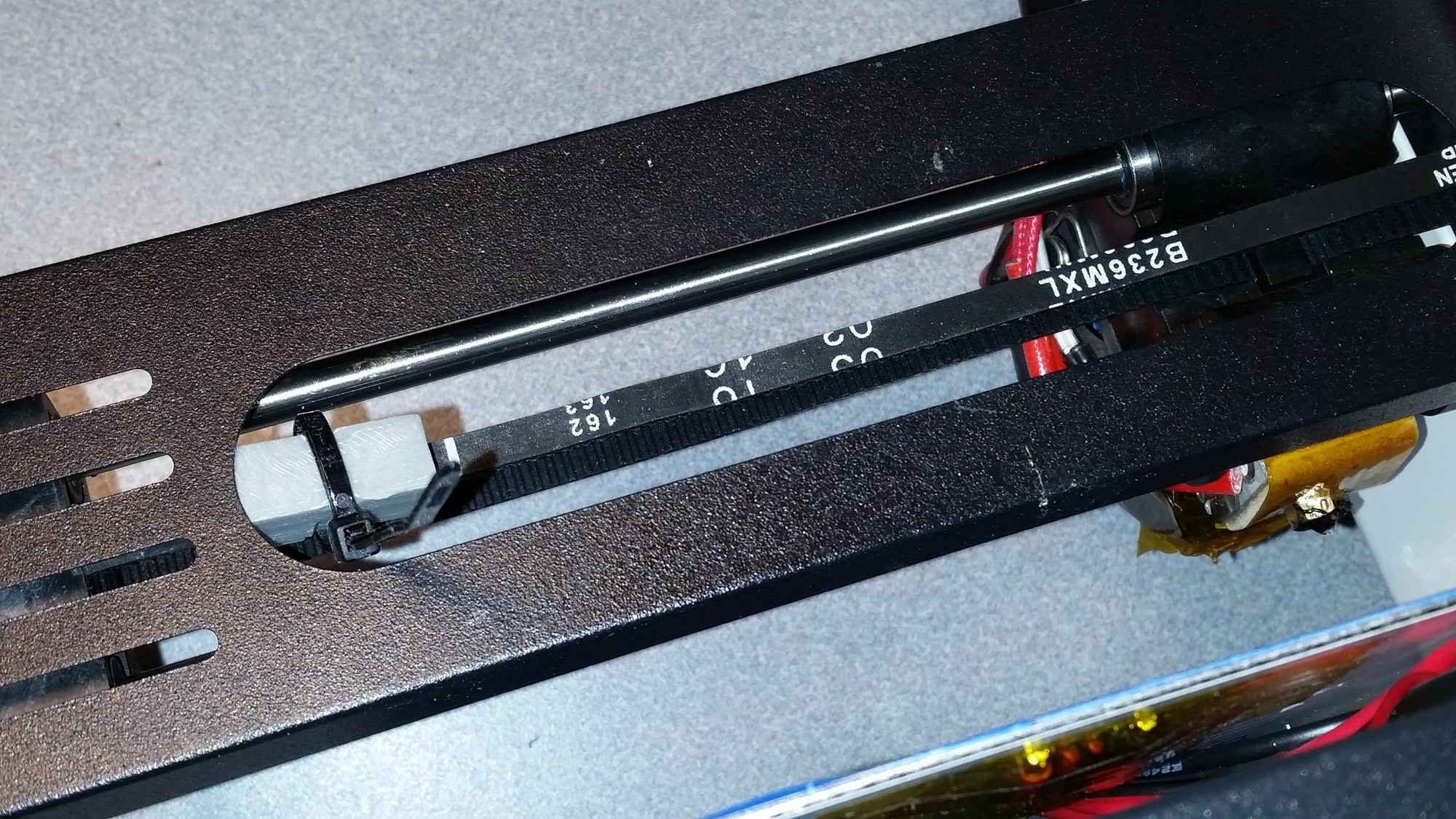
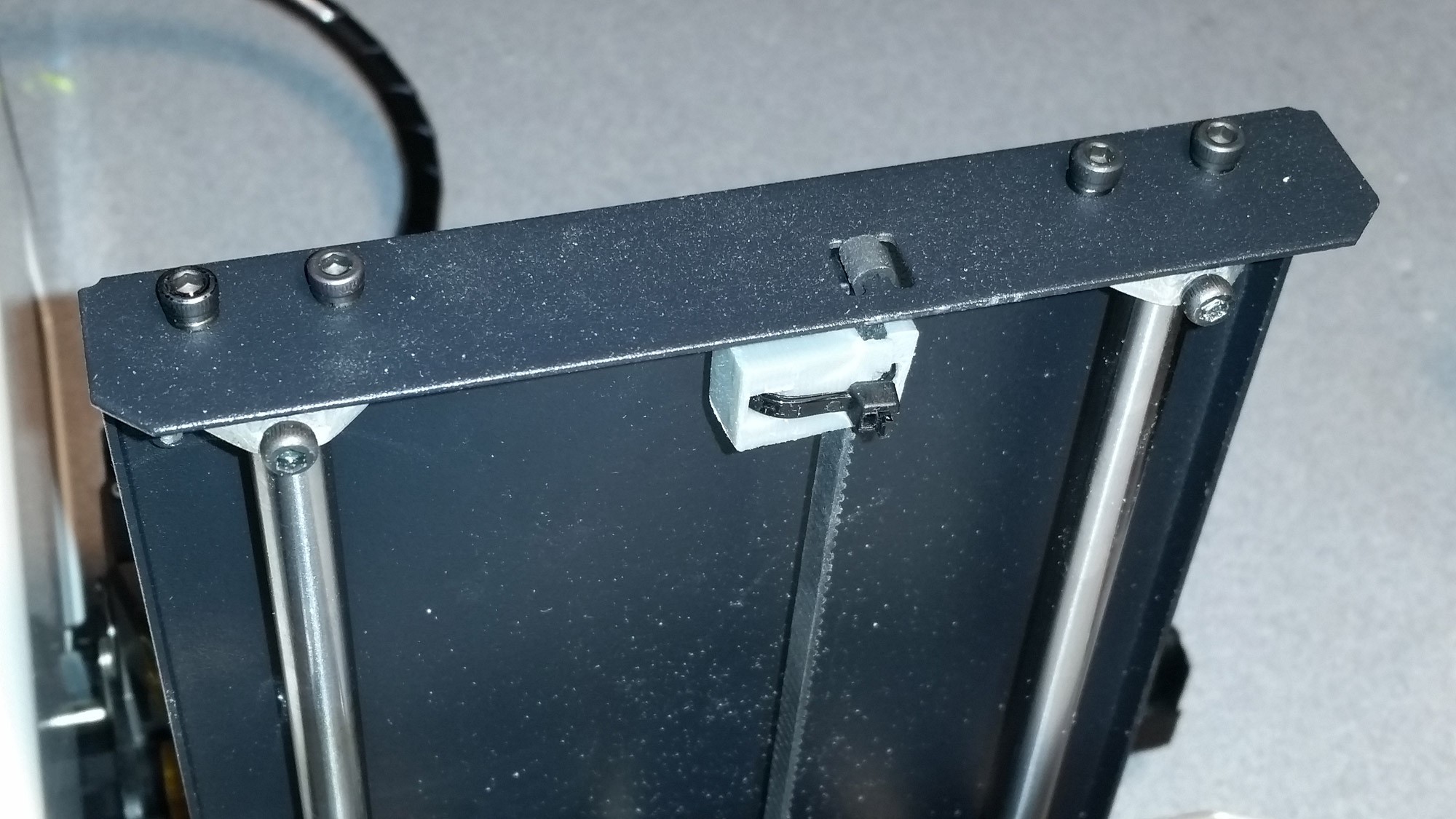
The X-Axis belt runs behind the extruder carriage and is the more difficult to install. The tensioner and clip must be installed on the belt so that it does not hit the pulleys when the extruder is fully travelled to either end. You can find a suitable spot to place the clip by moving the extruder head to the minimum and maximum position and finding a spot along the belt in the middle of those extents.Also be careful to place the tensioner on the belt with the larger side facing the rear of the printer, or the clip could rub on the carriage as it passes by.
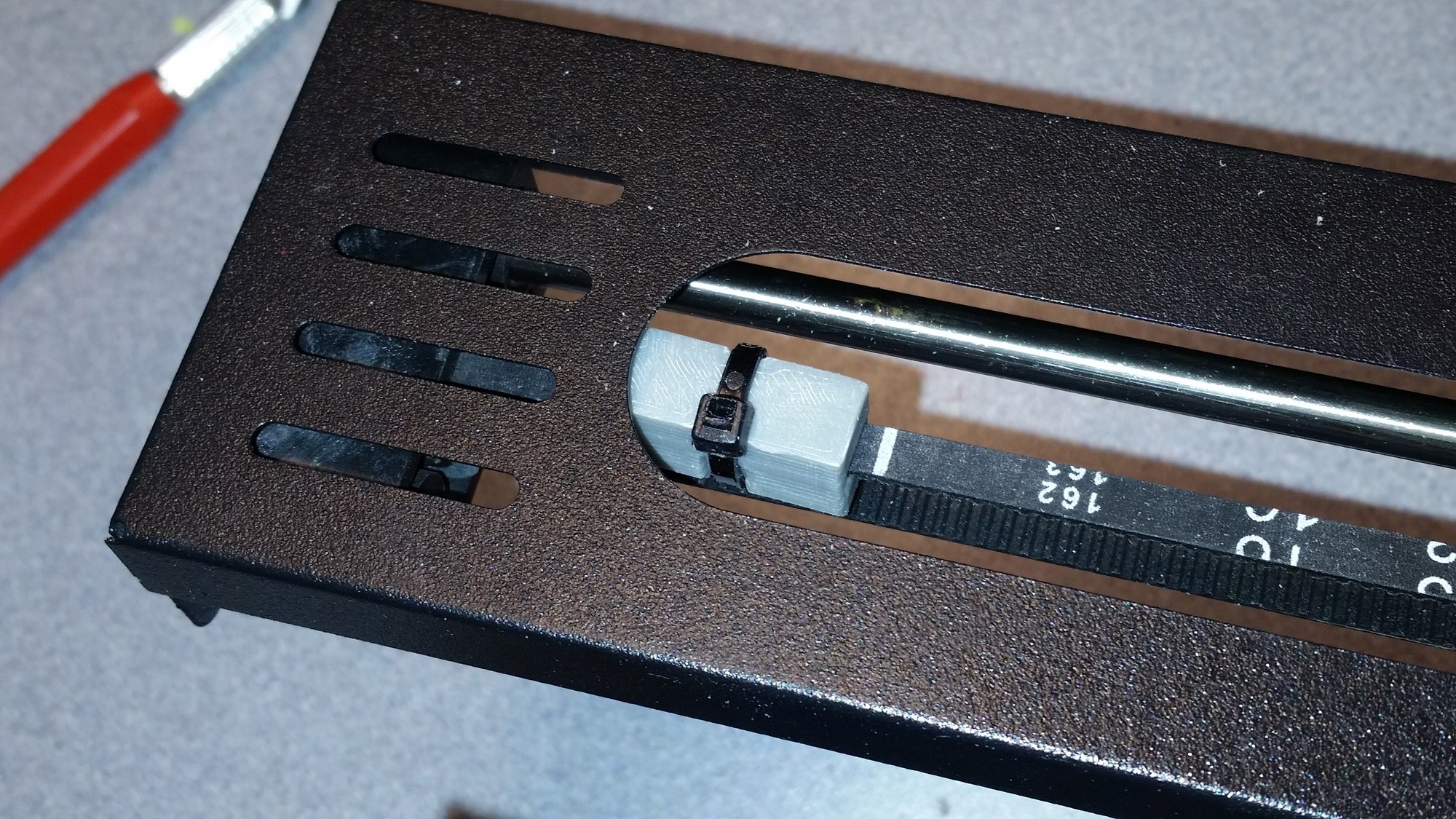
Position the tensioner as shown and support it with the cable tie.
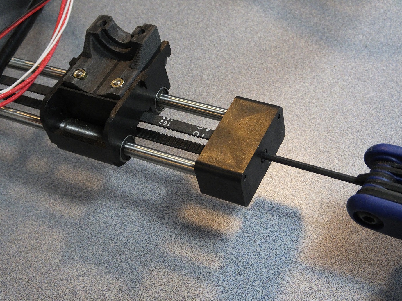
Loosely close the tensioner with the cable tie and test that it is in the location you prefer.
Then you can tension the cable tie to tighten the belt and trim off the excess cable tie.
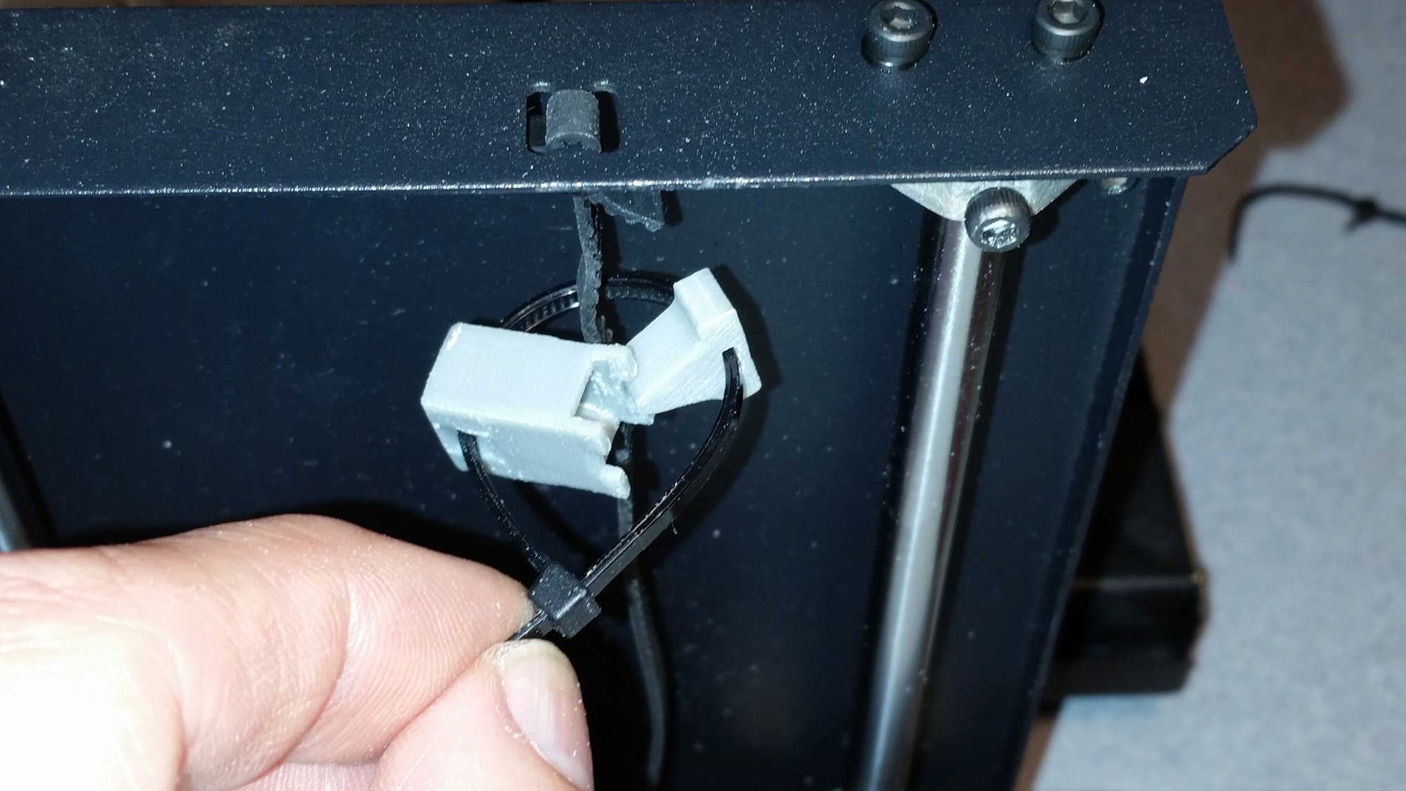
The second clip for the Y belt is located under the metal tray that supports the build plate near the front of the printer. This one is easy to install with no real issues.
Place the Y Axis tensioner as far forward to the front of the printer as possible. that will insure it will not interfere with the pulleys under the tray or the limit switch.
Adding the clip to the Y belt put increased tension on the Y axis bearings, and eliminated some noticeable slop in the bearings on the stock printer. The total cost of this upgrade was a few cents in filament and cable ties? Maybe $0.25 if you really rounded up?
This upgrade was well worth the effort.
Monoprice Select Mini Maximum 3D Printer Mods
Low/zero cost upgrades for the Monoprice Select Mini 3D Printer.