-
X-Axis GT2 Belt Upgrade E3Dv6 Carriage
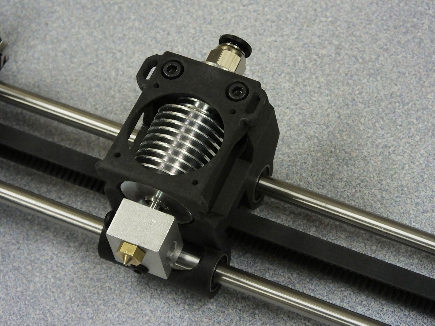
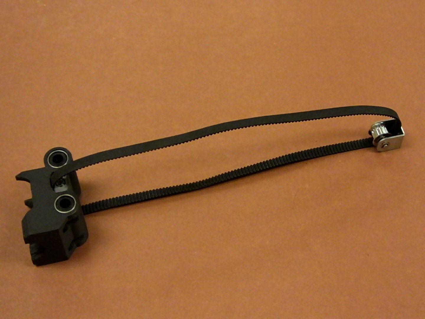
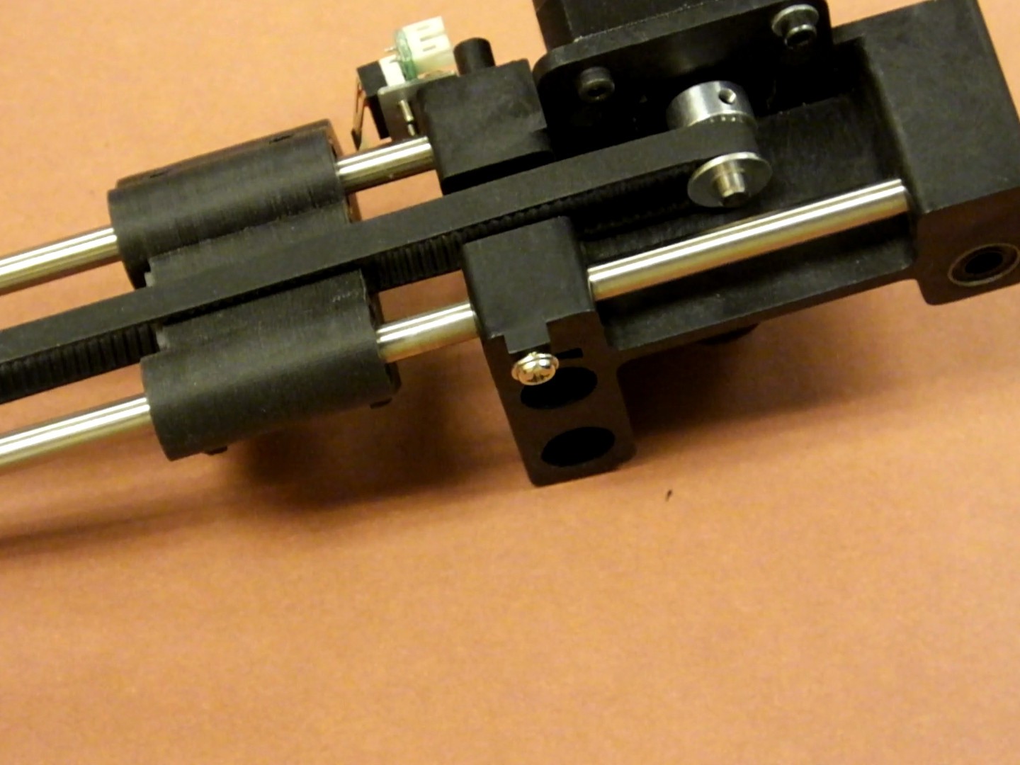
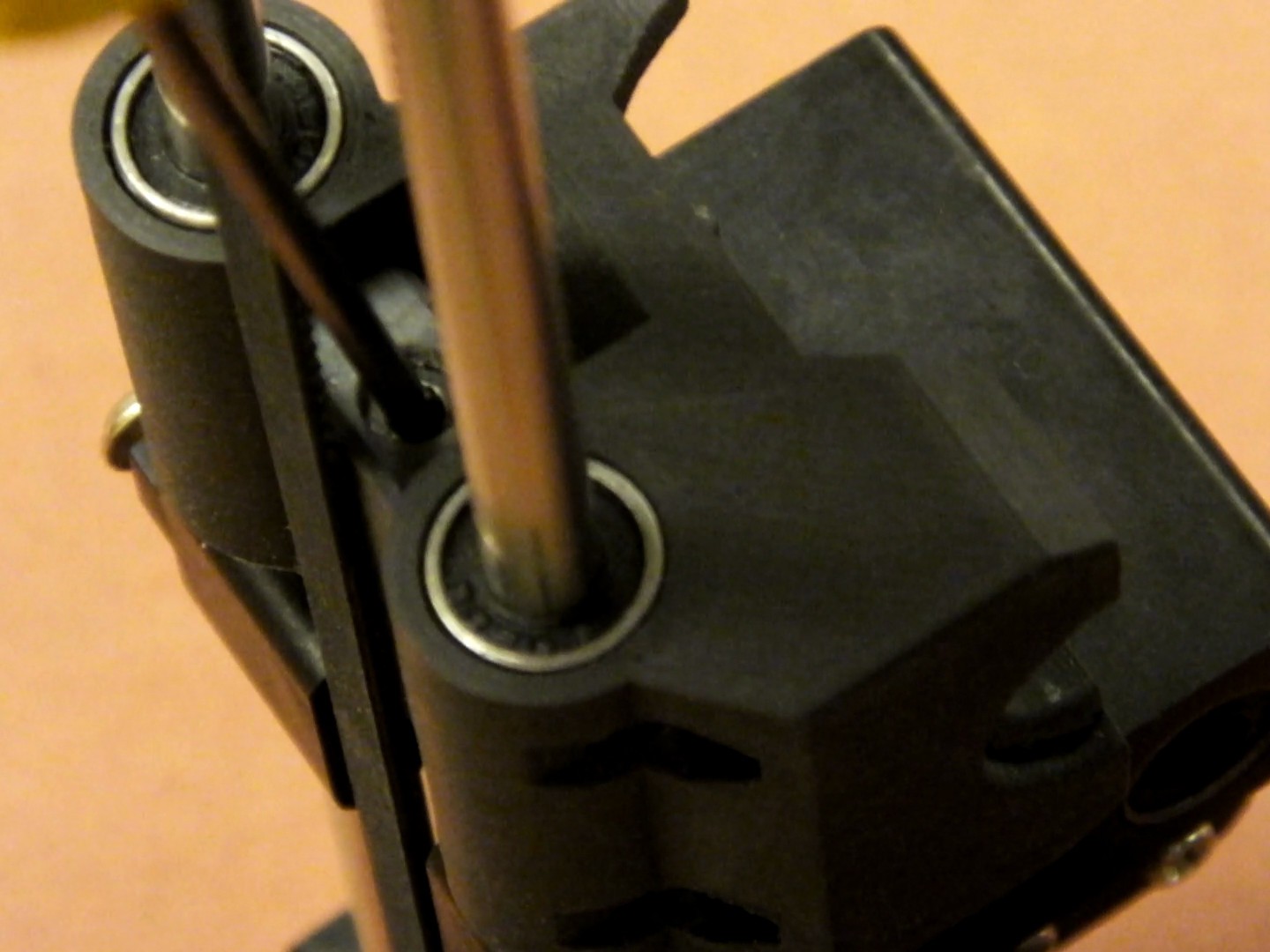
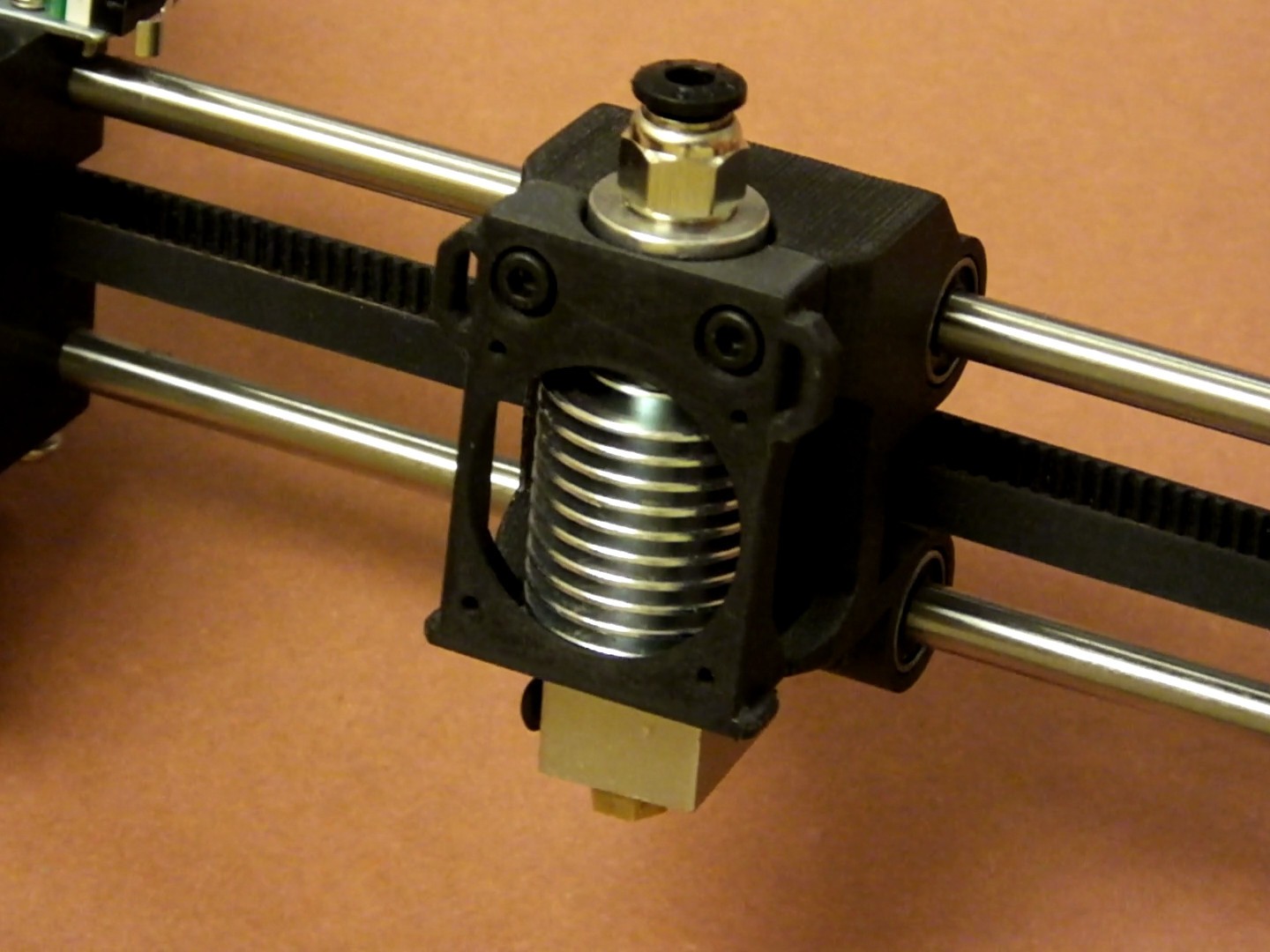
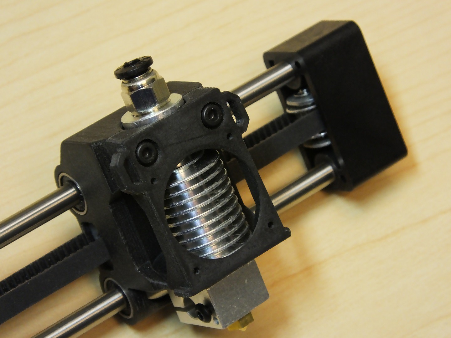
05/23/2017 at 20:14 • 14 commentsThe purpose of this modification is to completely replace the stock Monoprice Select Mini V1/V2 X-Axis Carriage with a 3D printed replacement part, which will serve as a E3Dv6 compatible hot-end mount, but will also feature an integrated belt attachment and tensioning system for a GT2 timing belt. The X-Axis belt and pulleys will need to be replaced, and you will likely want to install fresh LM6LUU bearings on the new carriage, to obtain a smoother operation than stock, and avoid having to extract the existing bearings from the stock carriage.
The 3D printable files for this project can be found at the following links:
https://www.thingiverse.com/thing:2353376 (Carriage and Belt Tensioner Clamps)
https://www.thingiverse.com/thing:2049820 (Optional X-Axis Idler Pulley Alignment Clip)
https://www.thingiverse.com/thing:1848402 (Optional Clip-On Fan Shroud part from our Zero-Offset E3D Adapter)
To perform this upgrade, you will need the following hardware:
2x LM6LUU Linear Bearings
480mm (48cm) GT2 Timing Belt, 6mm wide with 2mm pitch
1x 16T GT2 drive pulley for 5mm shaft
1x 16T GT2 bearing idler pulley for 3mm shaft
Before starting this project, go to our thingiverse page and download and print out the printed components associated with this project. You will need to print the new X-Axis Carriage, the Hot-End Clamp/Fan Shroud, the Idler Pulley Alignment Clip, and the Clip on Part Cooling Fan mount (This is identical to the mount used on the Zero Offset E3Dv6 mount, so you may already have this on your printer, if you did that upgrade).
Make sure you have the parts printed and are satisfied with them before starting this mod, because you will not be able to print new parts once you have started this upgrade. Also, be sure you print the new X-Axis Carriage and Fan Shroud in a reasonably high temperature filament. Plain PLA has been known to melt in proximity to the hot-end components. Our example print is in carbon fiber filled PETG.
 You will also need some fasteners for this project. You will need one 25mm M3 socket cap screw, two 16mm M3 socket cap screws, and three M3 Nylock nuts. You can use standard nuts, but we strongly recommend the use of Nylock nuts because they will not vibrate loose.
The first assembly step is to remove the existing hot-end, heather, thermistor, fans, and wiring from the stock X-Axis carriage. In these instructions the assembly instructions have been photographed with the complete X-Axis assembly removed from the printer for clarity, however, this upgrade can be done with the X-Axis installed in the printer with just the metal covers removed from the X-Axis and the Z-Axis gantry tower. The disassembly steps for the printer to get to this point have been omitted from this tutorial, because this is well documented in many other places, and is actually pretty obvious how to do anyhow.
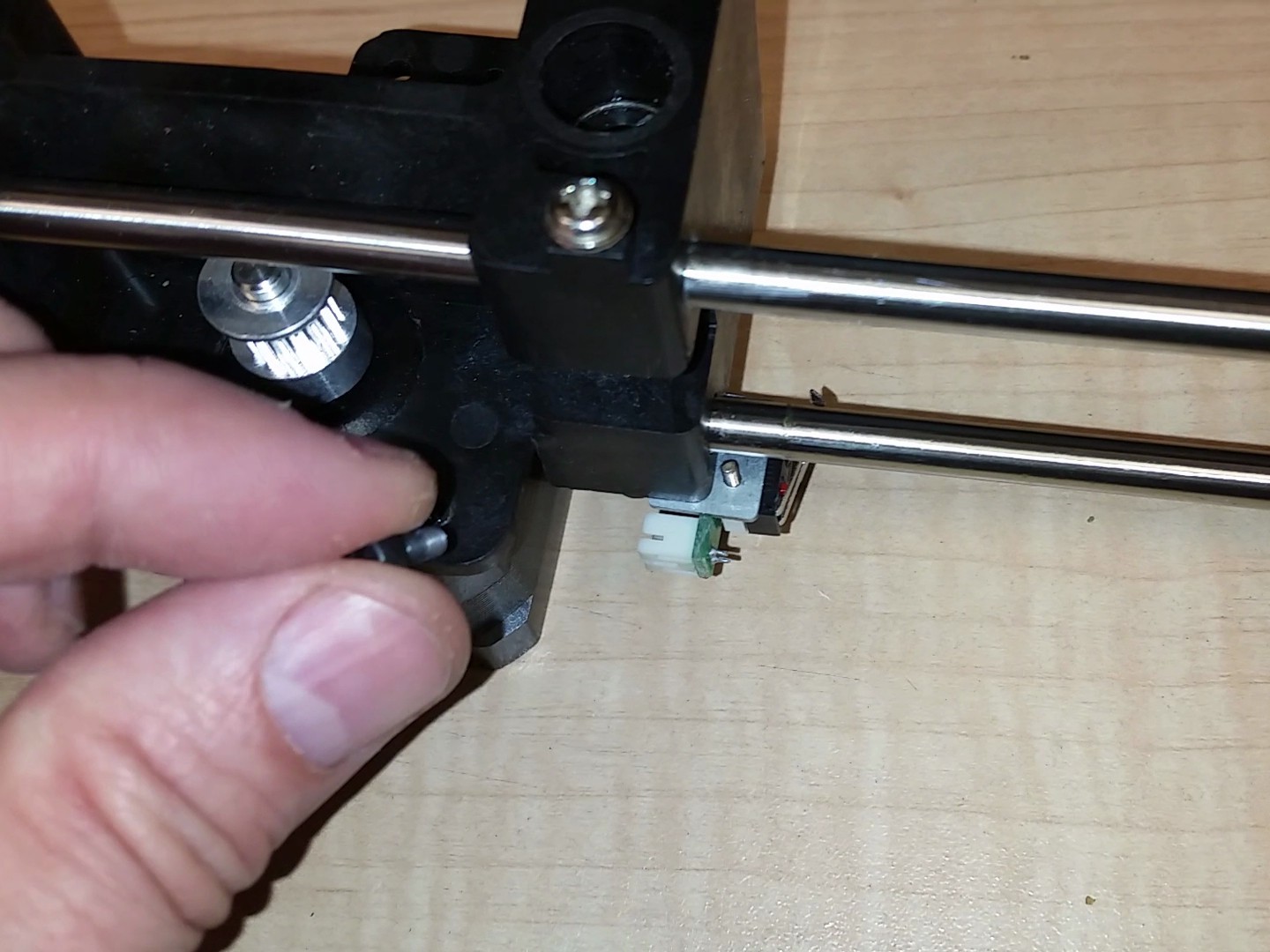
Remove the screw holding the X-Axis Pulley to the end of the X-Axis linear rods. Set this screw and pulley assembly aside for later. You will be reusing these parts.
 Gently tap on the inside of the plastic end cap for the X-Axis linear rods, until it pops off. It is just pressure fit on, and should come off relatively easily with a few sharp raps on the back side.
Remove the four M3 screws holding the X-Axis stepper motor to the gantry. Make a note of how your wiring is installed and routed, and also the orientation of the connector. You will need to note this so you can assemble it back the way it was originally installed. This seems to differ between different revisions of the printer.
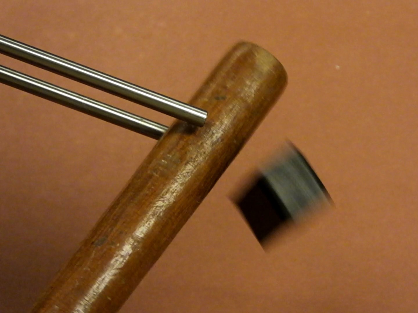
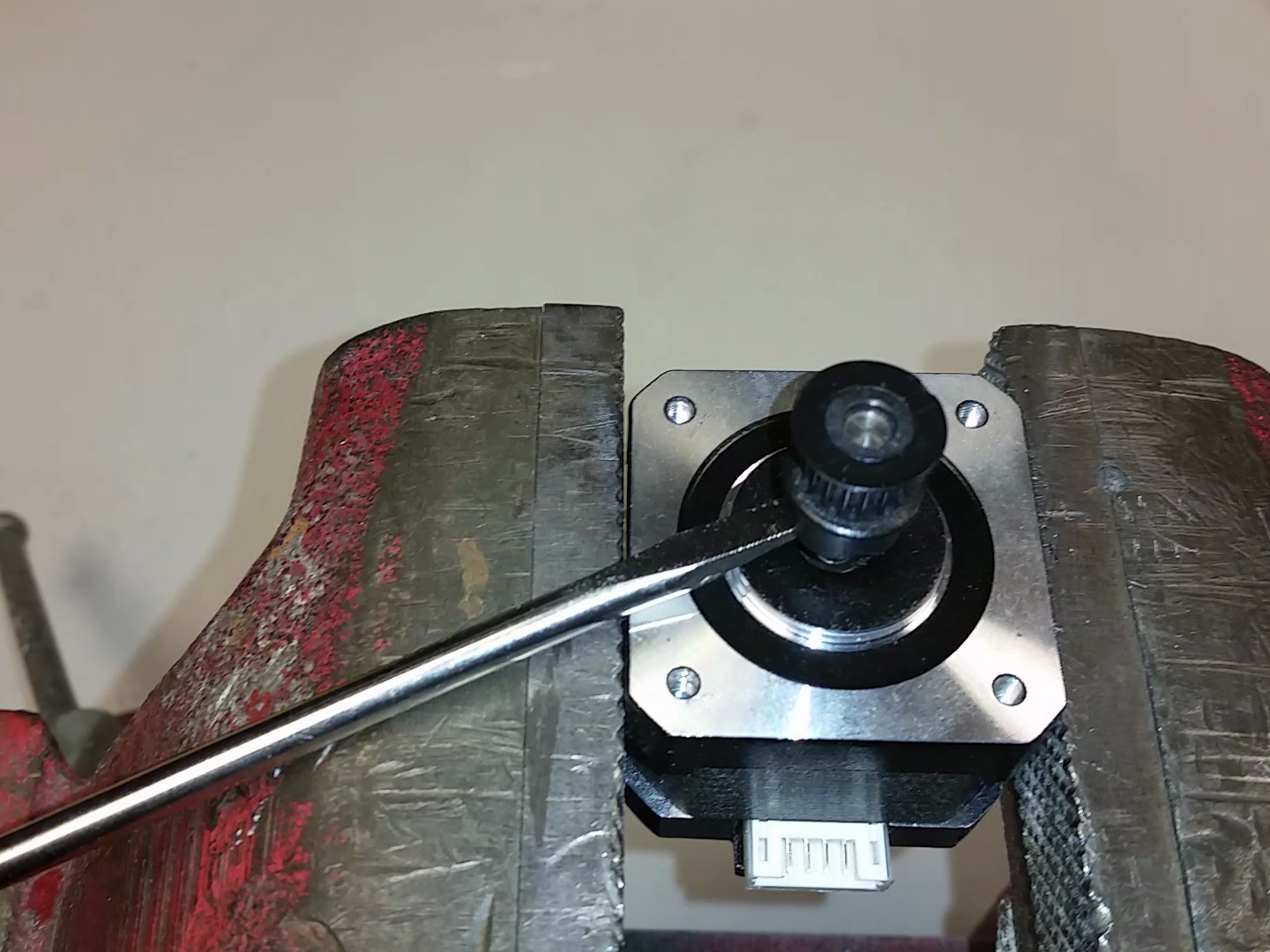
 Pry the plastic toothed pulley from the end of the stepper motor shaft using a thin flat screwdriver or similar tool. The pulley is just friction fit over the motor shaft, so it will just slide off with some prying force. If the pulley is very difficult to remove, you can try warming the plastic pulley with a heat source and it will expand and soften and more easily come off.
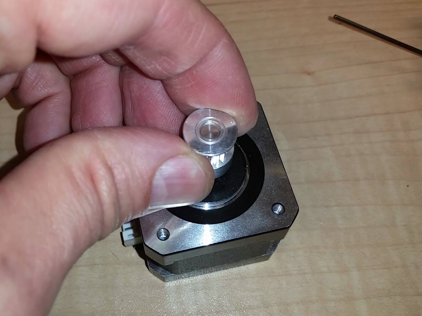
Install a new metal GT2 16T drive pulley on the stepper motor shaft. Don't fully tighten the grub screw because you will need to fine tune the height adjustment later.

Replace the stepper motor in the gantry and put the screws back in the same way they were when you removed the motor.
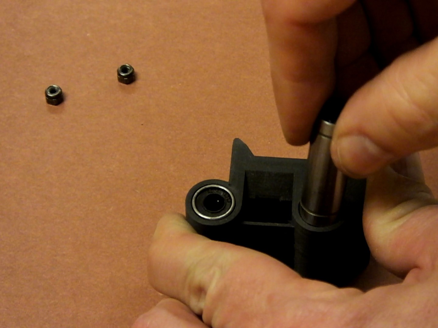
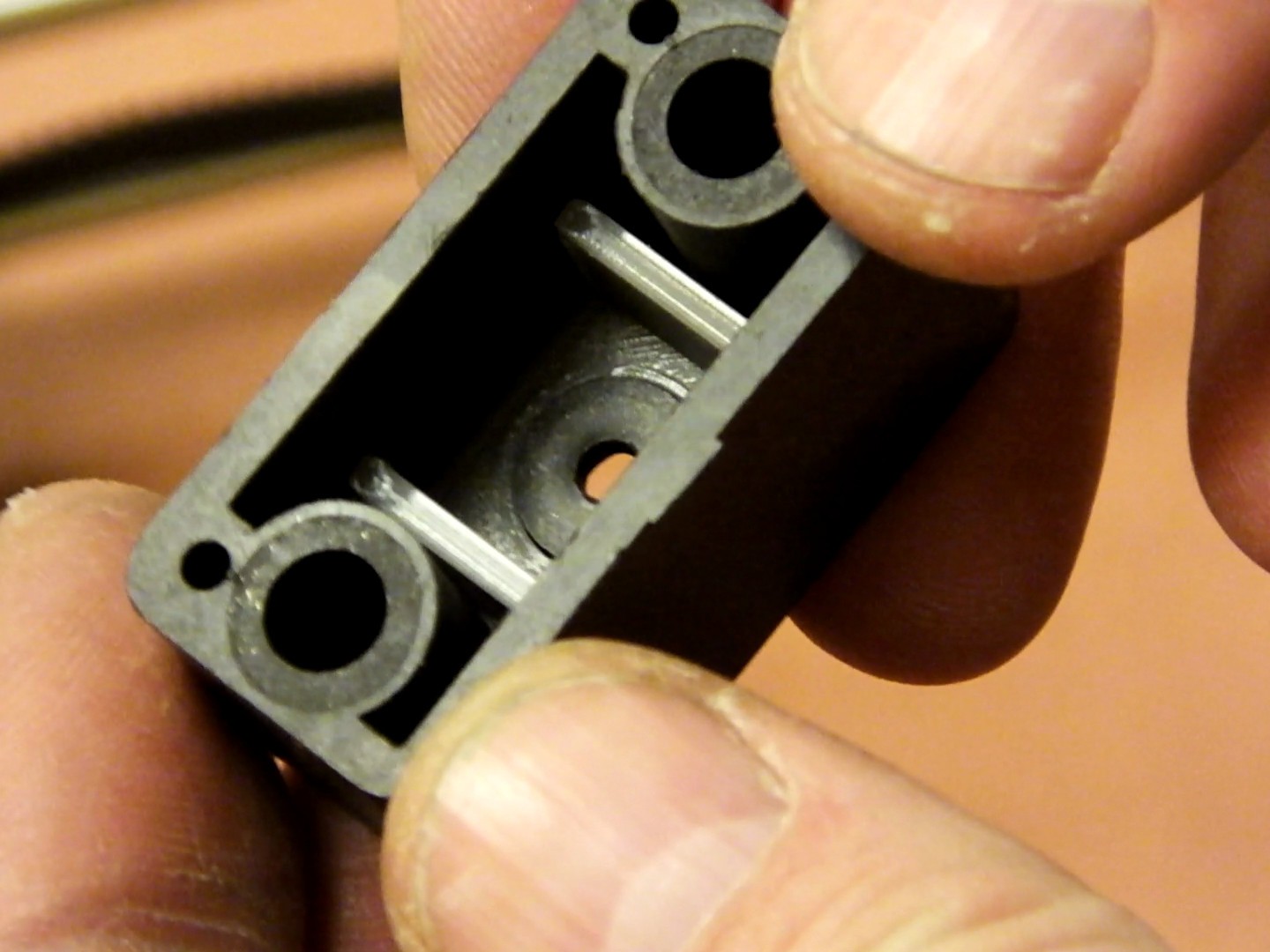
Insert the two LM6LUU bearings into the holes in the new X-Axis Carriage. The fit should be very snug. If you worry that the bearings may slip during use, you should put a little epoxy or CA glue on the side of the bearing before fully seating it.
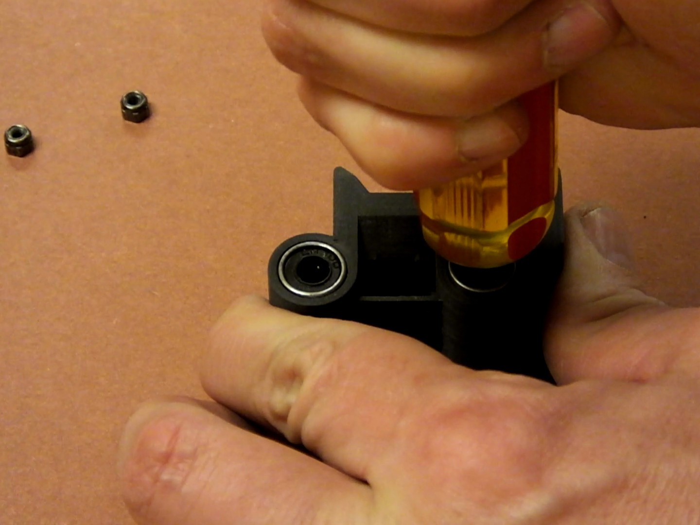
Press the bearings fully into the holes in the X-Axis Carriage. Do not hammer them or abuse them as you press them in.
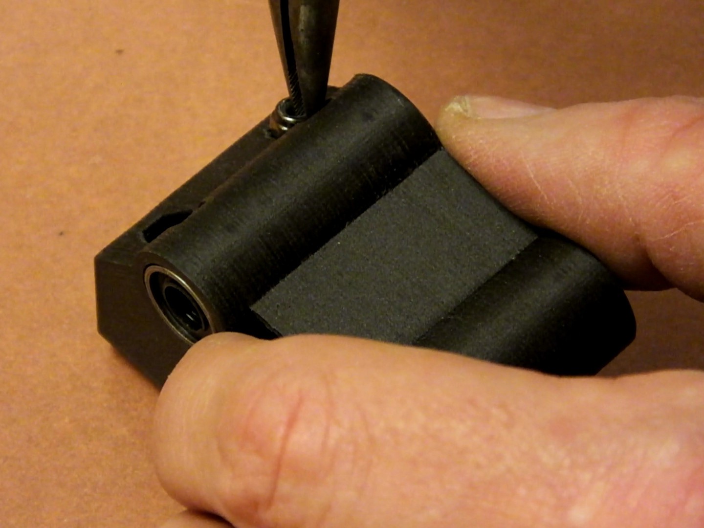
Insert two of the M3 Nylock nuts into the rear of the new Printed X-Axis Carriage. They should snap into place at the bottom of the holes.
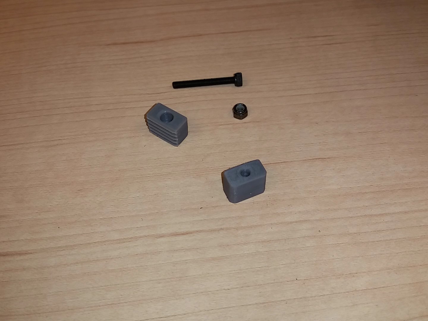
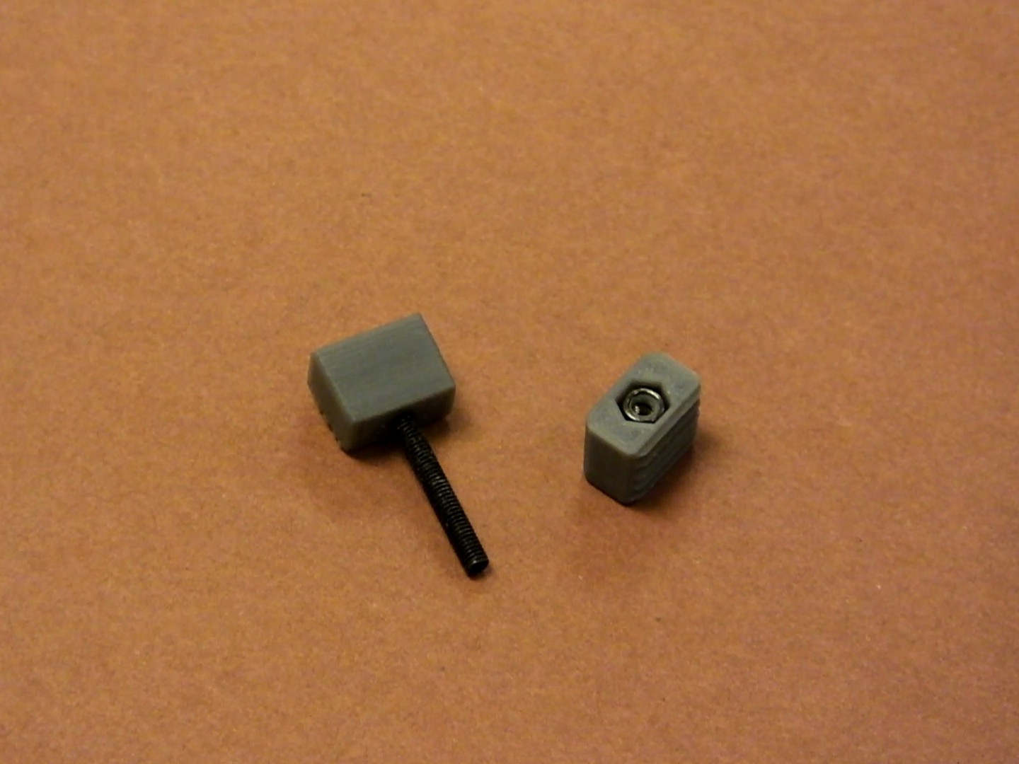
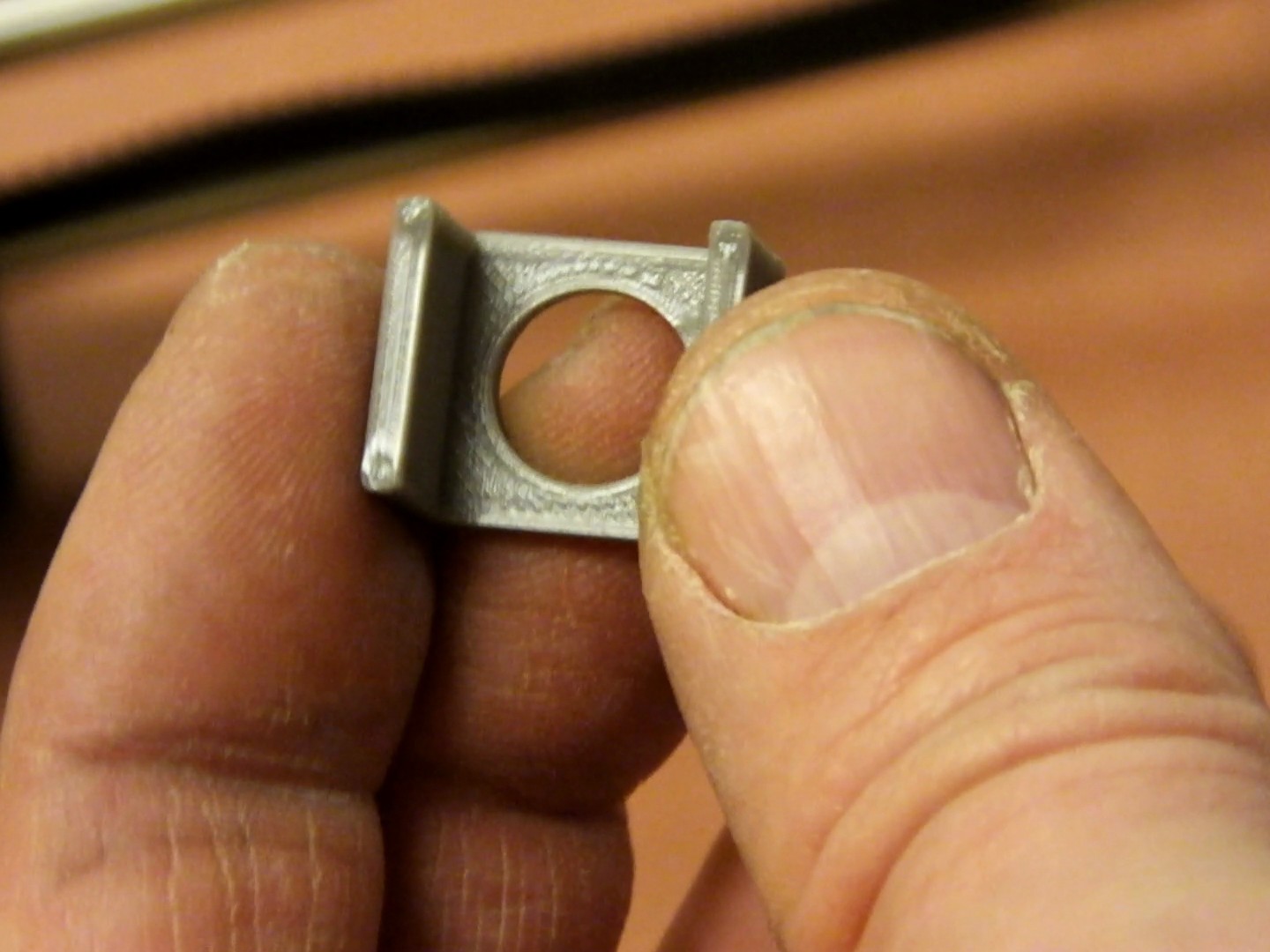
Insert an M3 Nylock nut and the 25mm M3 socket cap screw into the two halves of the GT2 Belt clamp, as shown here.
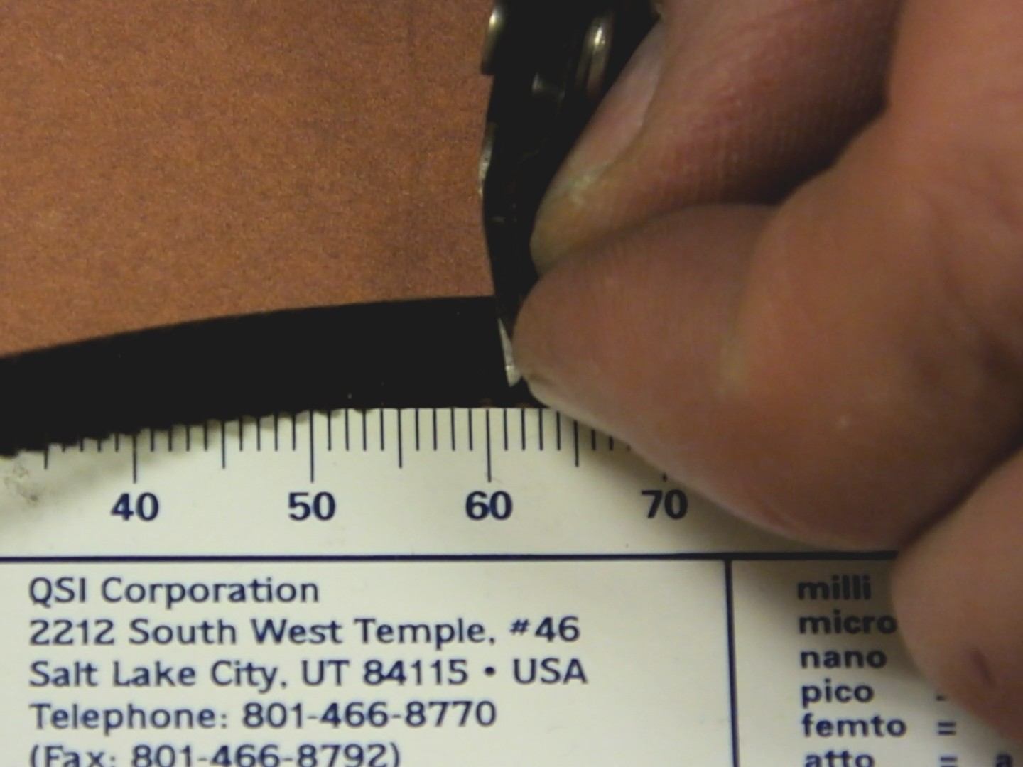
Cut a length of GT2 belt to 480mm (48cm). You can match the new belt to the one you took off to make sure you got the size correct, because the new belt will be the same size if you put them side by side.
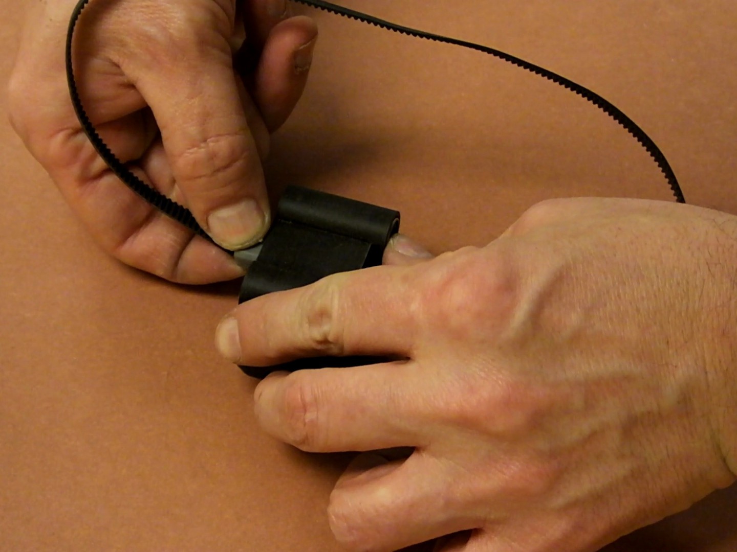
Align the GT2 belt end with the GT2 clamp which has the 25mm M3 screw through it.
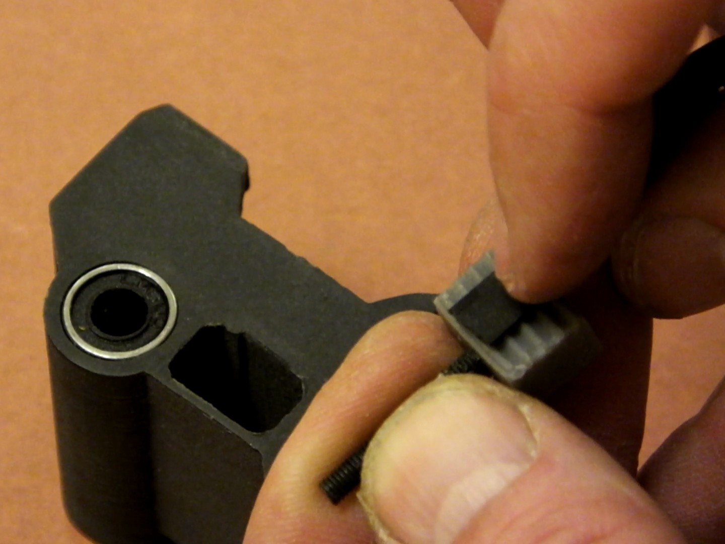
Insert the GT2 belt and clamp and screw into the right side of the new X-Axis Carriage. The teeth of the belt should face to the back of the carriage. The right side of the carriage has a more recessed hole for the clamp, the left side you will notice has no recess. Note: the recess allows for clearance of the idler pulley when then X-Axis is fully moved to the right, which gives another 3-5mm of X-Axis width to your printer.
Mate the GT2 clamp with the nut inside to the other end of the GT2 belt (make sure there are no twists in the belt) and insert this clamp and belt into the left side of the X-Axis carriage. Thread the screw of the right side GT2 clamp to the nut in the left side GT2 clamp at little bit, so the assembly does not fall apart while you continue to work.
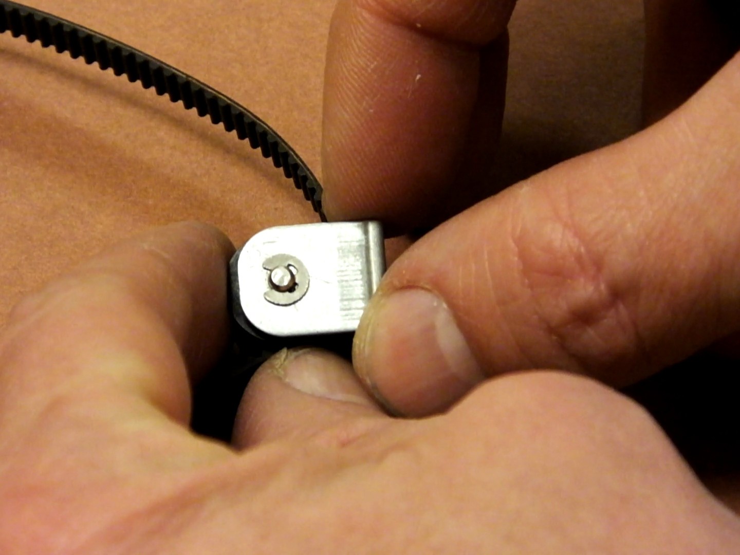
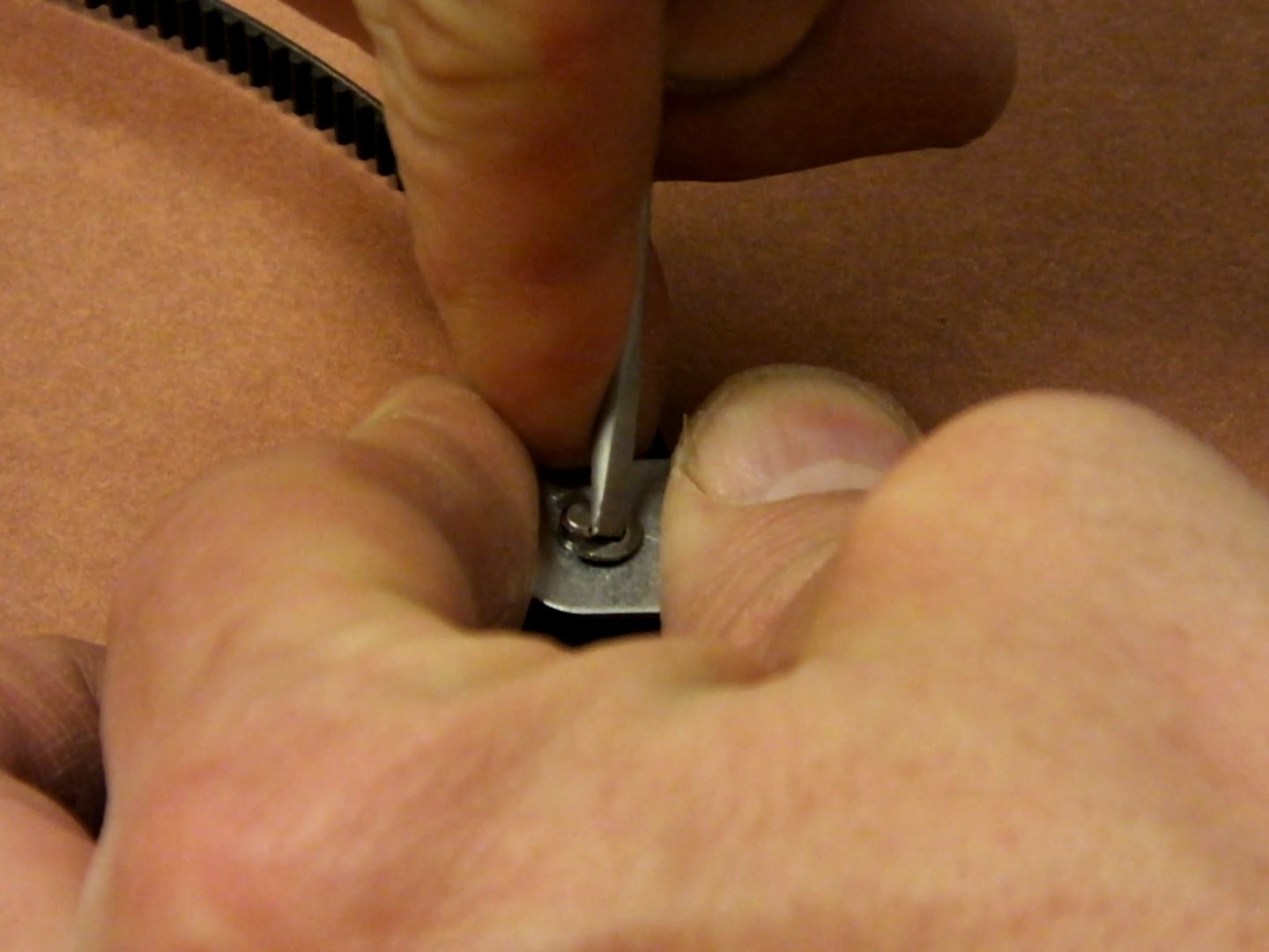
The original belt should still have the original pulley and bracket installed. You need to remove the C-clip that holds the pulley axle in place.
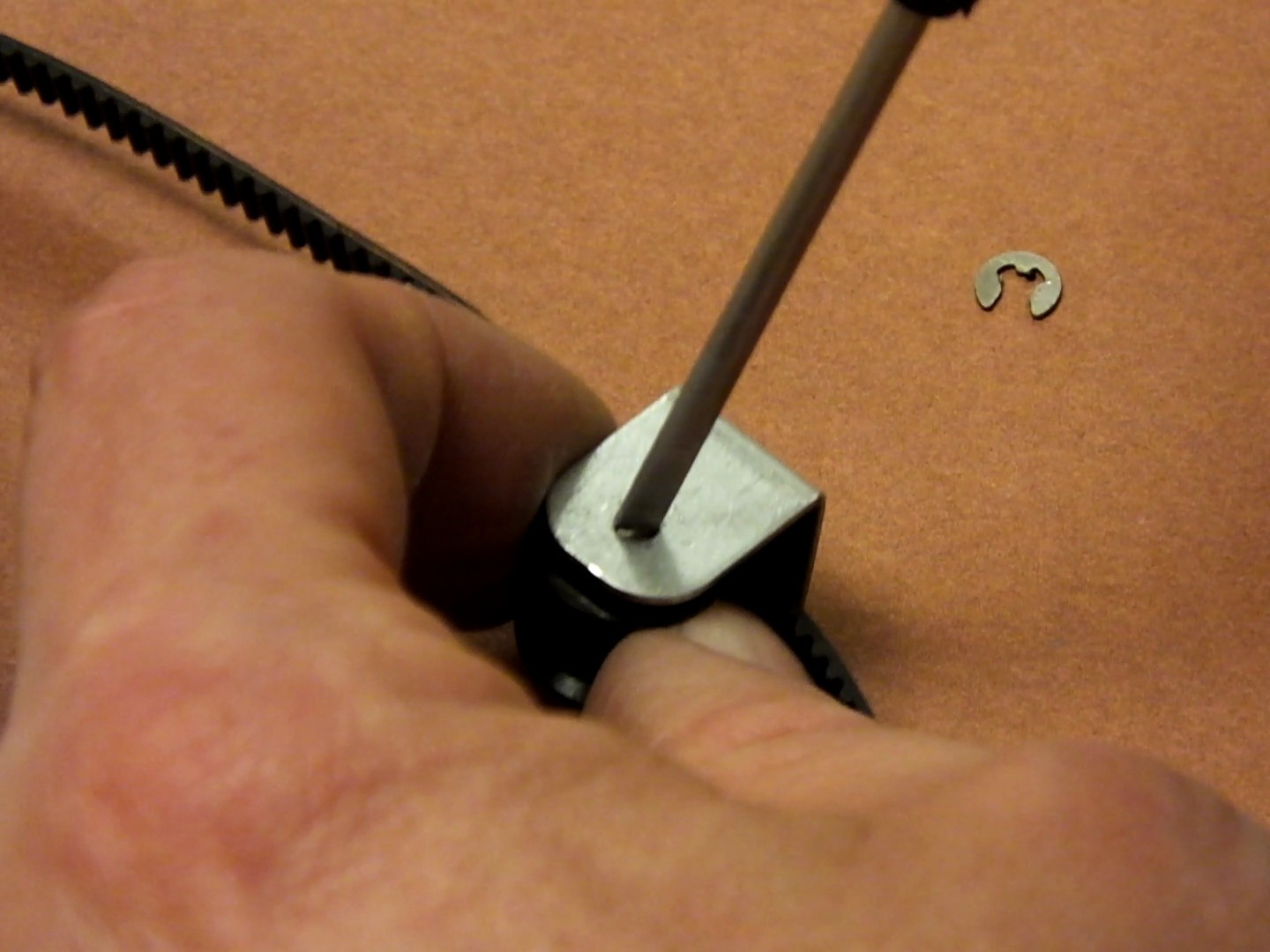
Slide the C-clip away from the axle as shown. Be careful it does not spring free and get lost.
Slide the axle out of the bracket and remove the old belt and pulley.
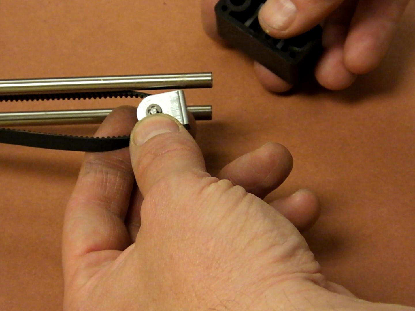
Insert the new GT2 belt through a new metal GT2 16T bearing idler pulley, and re-assemble this to the bracket and axle with the C-clip as shown here.
Install the optional pulley anti-rotation alignment clip, to make sure your pulley is perfectly aligned.
The pulley alignment piece fits into the end cap of the X-Axis before installing the pulley bracket, and prevents it from rotating.
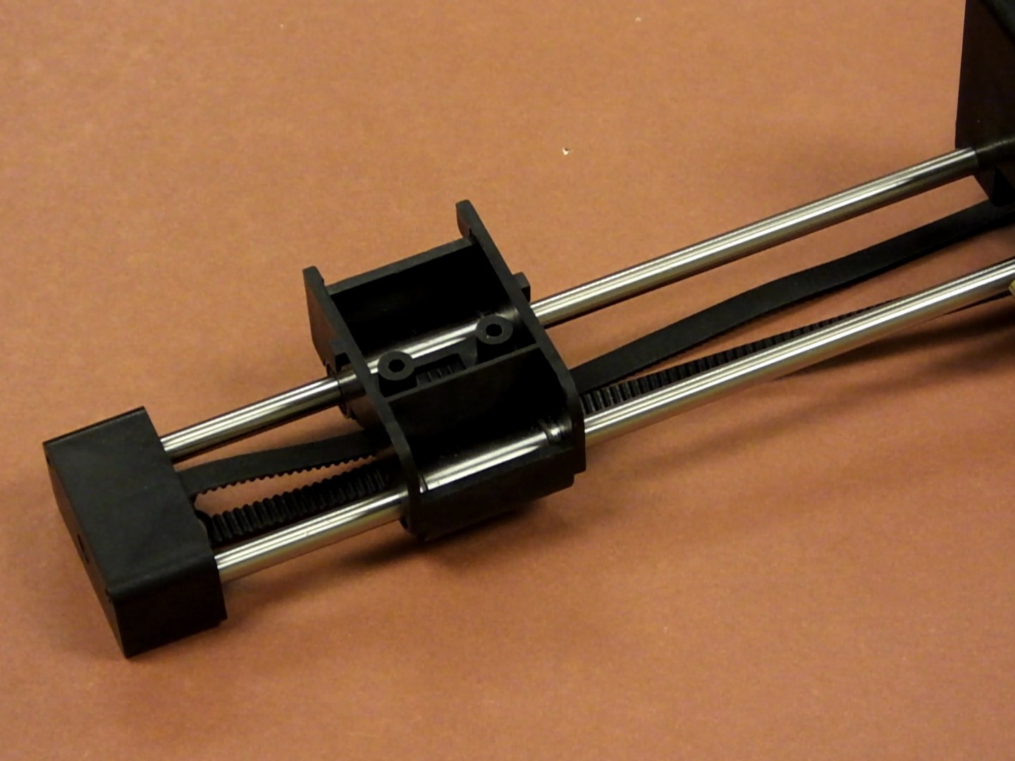
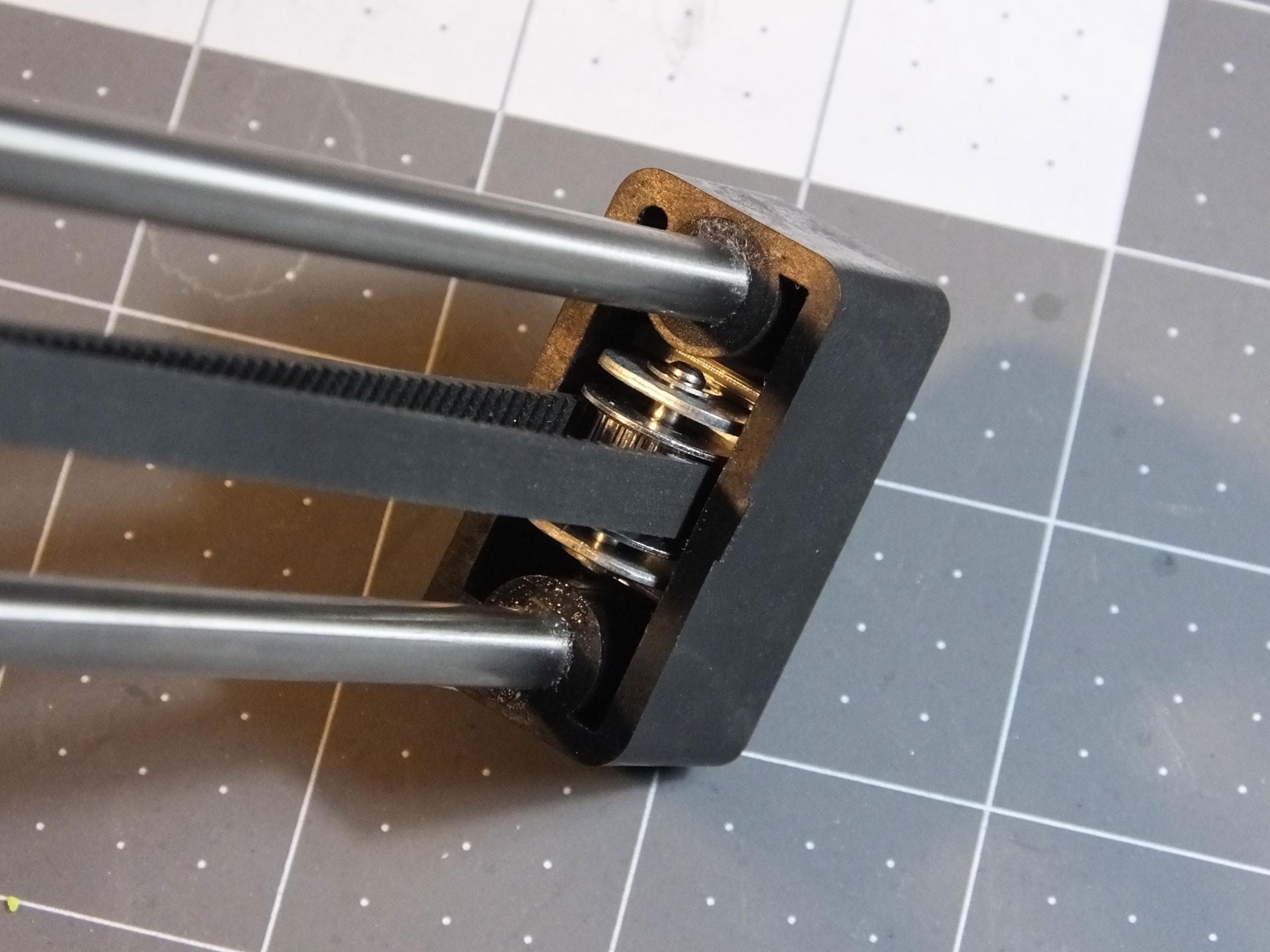
Slide the X-Axis Carriage over the linear rods and then make sure the belt is straight when the pulley bracket is inserted into the X-Axis end cap as you slide it on over the ends of the X-Axis linear rods.
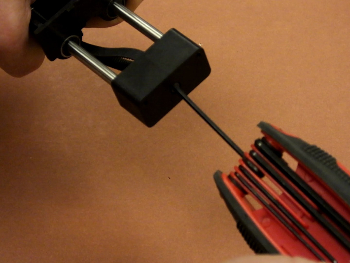
Replace the screw holding the pulley bracket in place and tighten the screw. Tap the end of the plastic X-Axis end cap to fully seat it on the ends of the linear rods. Make sure the new GT2 belt is looped around the new GT2 drive pulley on the stepper motor.
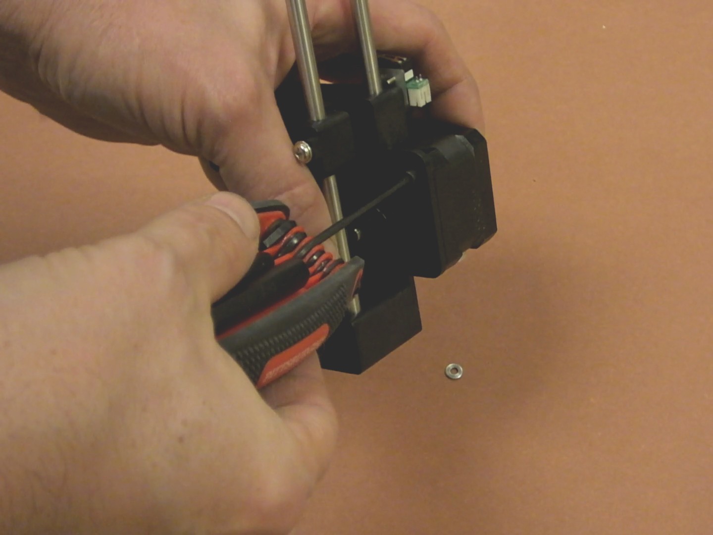
Loosen the grub screw on the stepper motor pulley, and fine tune the alignment of the pulley with the path that the belt takes. You want the belt to be perfectly straight and parallel. Then tighten the grub screw holding the pulley to the stepper motor.
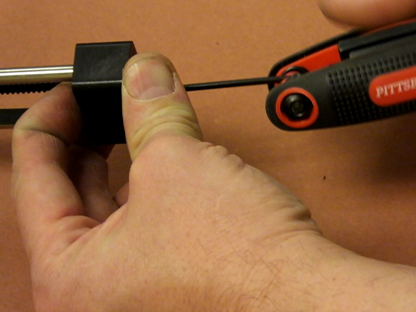
Tighten the 25mm GT2 clamp screw to tension the new belt to your liking. It should be taught, but not so much that it becomes difficult to slide by hand.
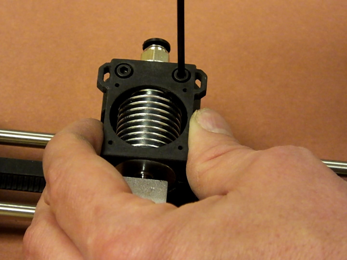
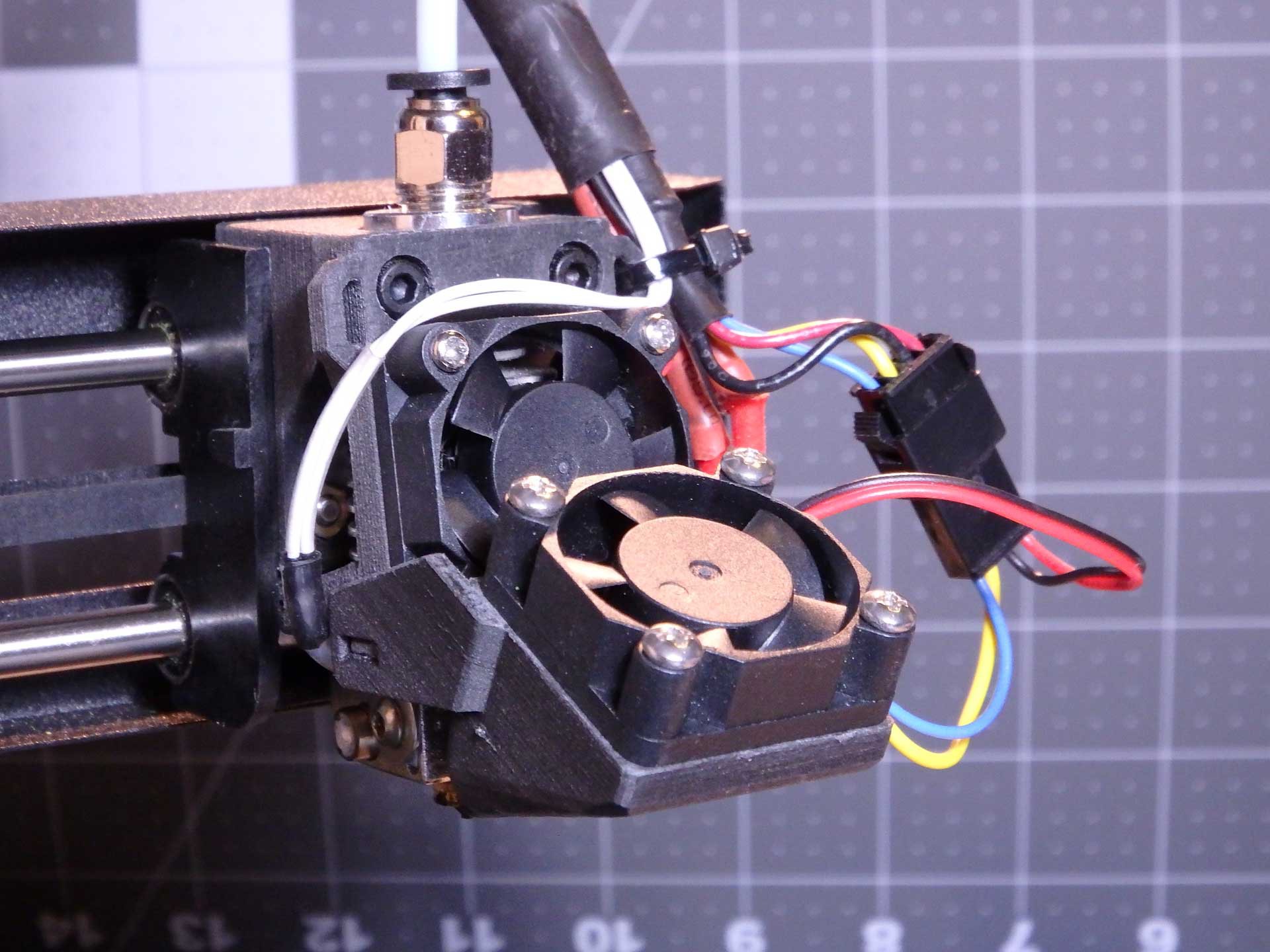
Install an E3Dv6 style hot end into the new X-Axis Carriage.
Two 16mm M3 socket cap screws secure the printed clamp/fan bracket to the new carriage.
You're ready to install the wiring back on the new hot-end and reassemble any parts of the printer you removed to get access to the gantry.
At this point, you should be ready to configure the main board with the new GT2 belt drive parameters.
Calibrating the printer CPU for the new GT2 X-Axis belt and pulleys is simple, and you must do this or the size of your prints will be wrong. You can use the calculator at www.prusaprinters.org/calculator to find out the correct steps per millimeter for my motor and lead screw combination. The X-Axis in the MPSM V1 is a 1.8 degree (200 steps per revolution) motor, and the printer can do 1/16th microstepping. The GT2 belt is 2mm Pitch and the pulley is 16 teeth.
Plugging those numbers into the calculator gives me a result of 100 steps per millimeter. The calculator even nicely reminds you that the G-code for this uses the M92 command. For the V2 the motors do 1/8th microstepping, so the result value is 50 steps per mm, so adjust the settings below accordingly.
All that's left to do is send this to the printer to tell it the new value for X steps per mm and we're done. The easiest way to make this happen is to open up a text editor and create a text file and stuff the commands into it and then save it as "xxxx.gcode" and take it to the printer and print "xxxx.gcode" (use any name you like in place of xxxx.gcode). The printer will read the settings and configure the printer accordingly. The extra commands in this print file are there to make the printer home the axis so you get some feedback that the file printed, and the motors turn off at the end so that you can move them axis by hand once the configuration is finished.
The file looks like this for the V1:
M92 X100 ; Configure X MotorM500; Save New Settings
G28; Home All Axis
M84 ; Disable All MotorsEnjoy your new carriage, and stay tuned for a similar fix for the Y-Axis!
-
Upgrade the Z-Axis with a NEMA17 Stepper and TR8x8 Leadscrew
03/24/2017 at 00:46 • 18 commentsThis mod breaks with the tradition in this project of doing everything at minimal cost. There's simply no getting around the fact that the Z stepper motor setup in the early Monoprice Select Minis which were produced, caused a lot of issues with Z-wobble and banding artifacts in prints. I was fortunate to come across a used Mini made in the summer of 2016 that exhibited some of these issues, and I was curious to find out if replacing the Z-Axis motor with a NEMA17 motor with an integrated Leadscrew would help. I also hoped that it would speed up the movement of the printer in Z moves, because the stock motor is so slow that configuring the slicer to perform Z-hops on retract actually makes blobbing worse because the Z movement time is long enough for the nozzle to drool. This project shows how the mod was done.
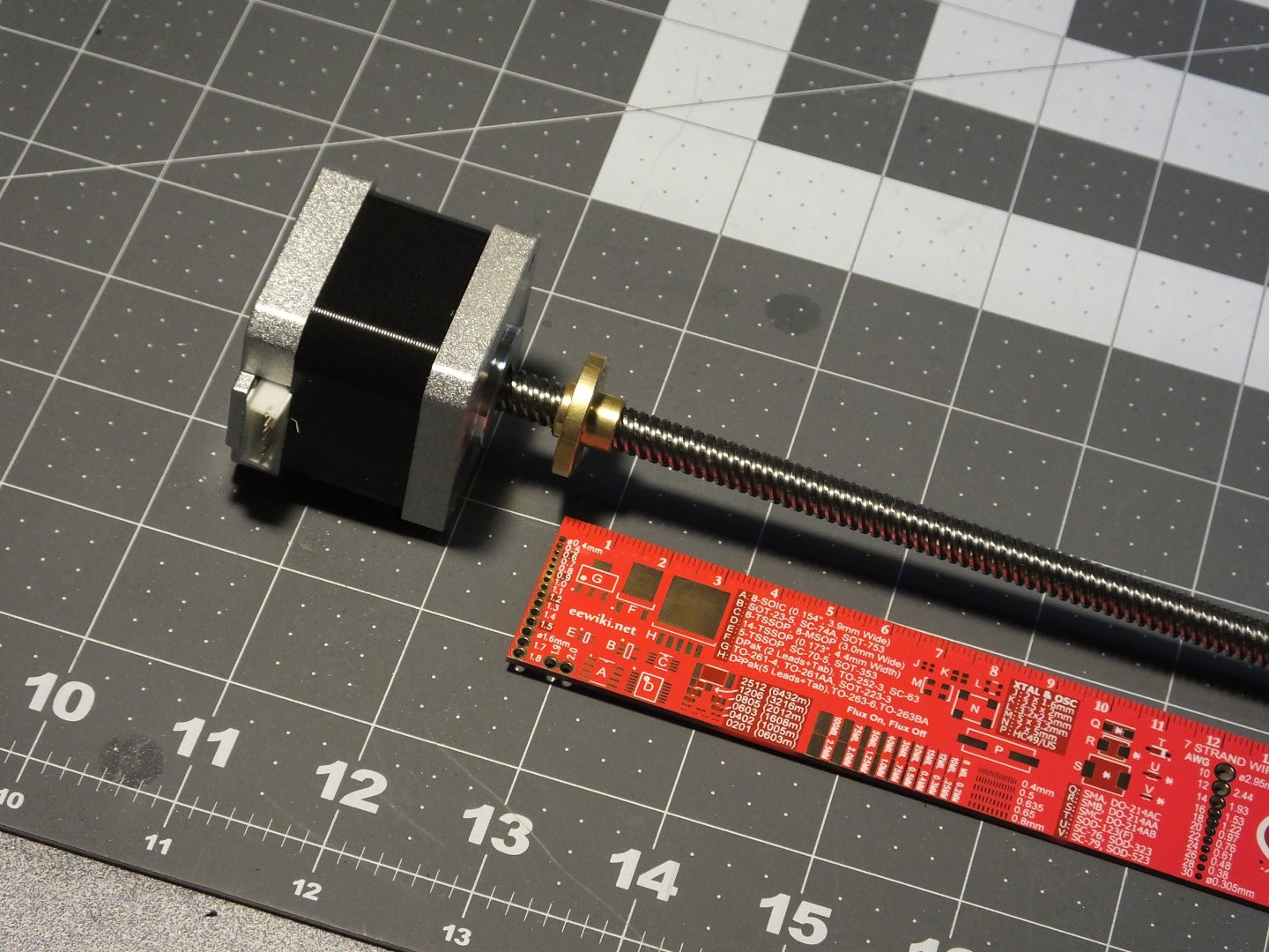
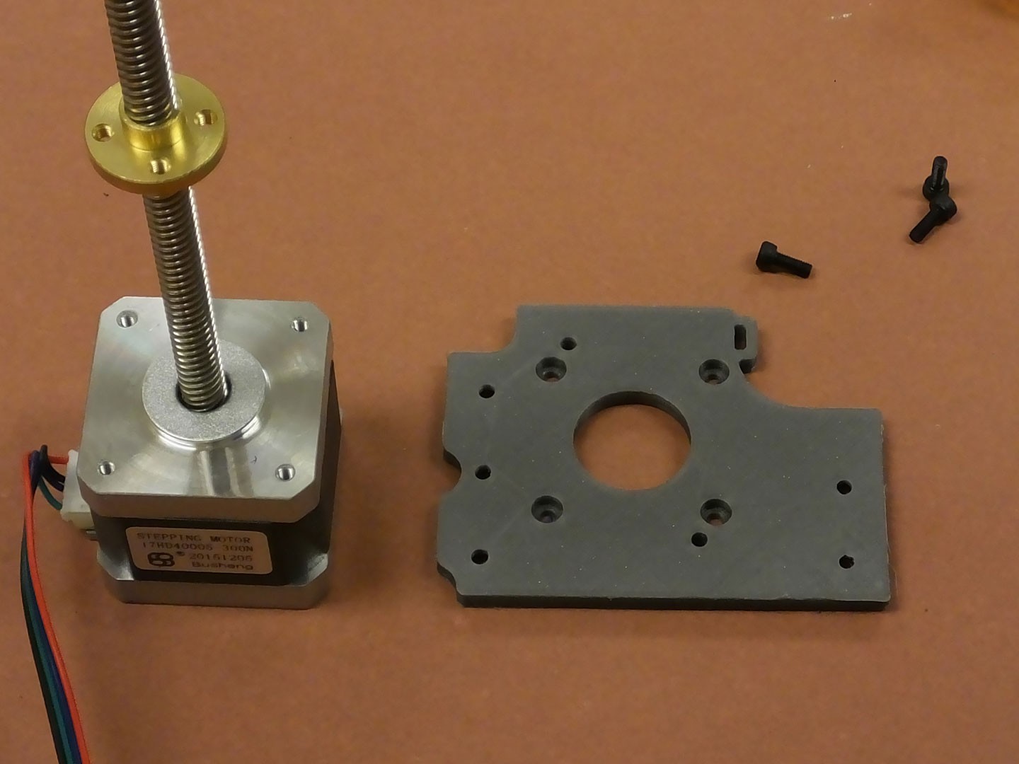
 The first thing you need is a NEMA17 motor with leadscrew with a matching nut. I was able to find several sets of them on Amazon.com, and they all seem to be made as upgrades for the Prusa I3 and clones. That means they all have a 300mm long lead screw. This value includes the portion of the screw inside the motor, so it's really about 260mm long. This is actually too long to fit inside the Mini. Note that you can probably get away with a separate motor and leadscrew using a coupler to join them. There should be plenty of room for the coupler under the X-Axis gantry. There must be a standard footprint for the nuts on these lead screws because the hole pattern in the new nut matched the holes in the X-axis gantry on my Mini exactly.
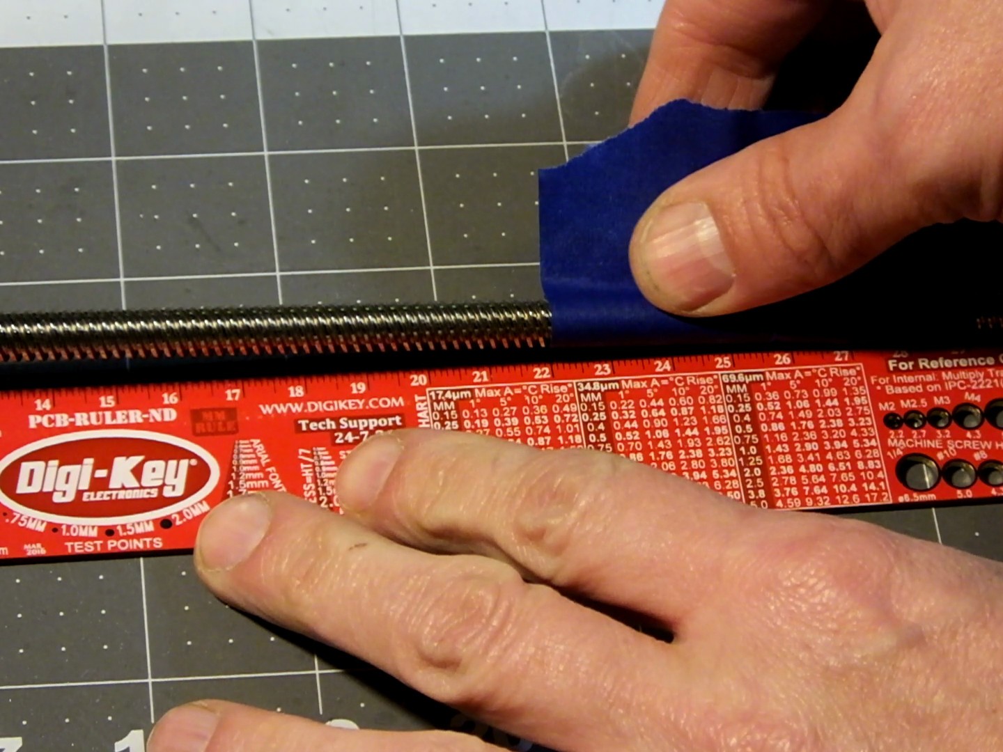
 Through some careful measurement and calibrated guesswork, I determined that the lead screw for the Mini with this modification should be 220mm in length, so I measured the correct distance from the top of the NEMA17 Motor, and marked the spot to cut with a piece of tape I happened to have laying around.
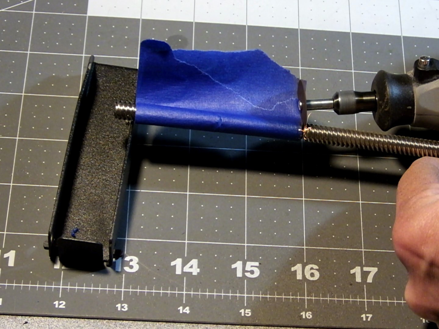
 I used a rotary tool with a cutting wheel installed to cut the leadscrew to the proper length. I tried to do this as carefully as possible and as straight as possible, by rotating the leadscrew by hand as I cut into it around the perimeter and toward the middle until the excess part fell off.
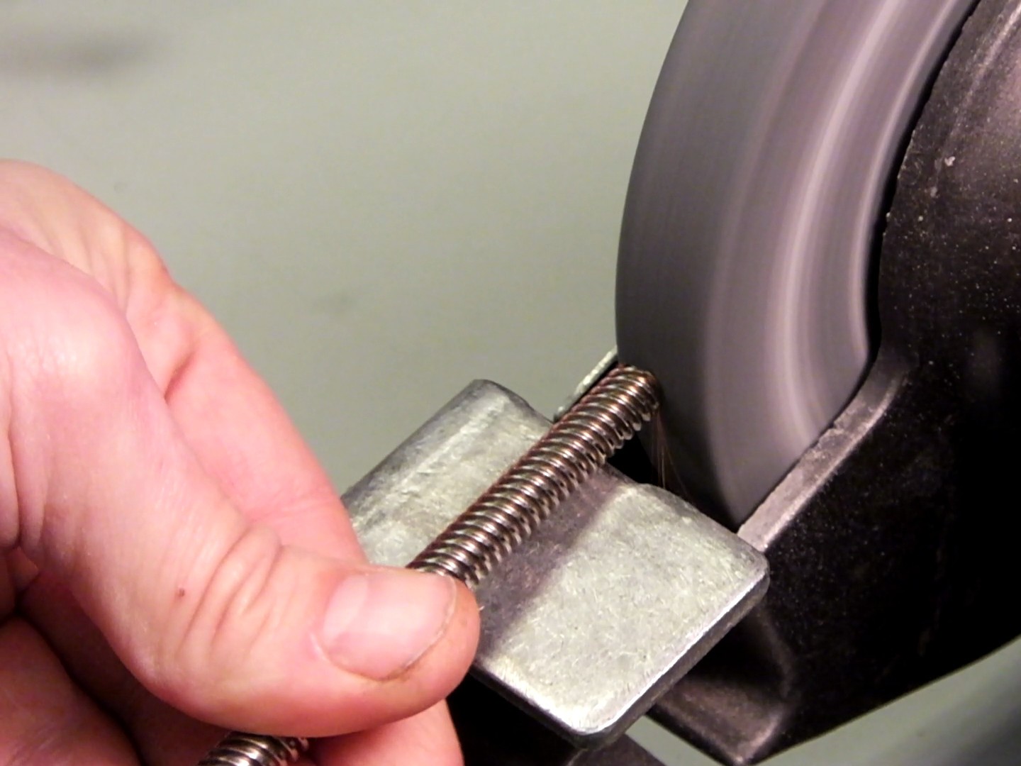
 The cut end of the lead screw was a little jagged and had sharp edges and it was difficult to get the nut to thread on, so I used a bench grinder to round off the end of the lead screw to get rid of the sharp edges. Now the not would go on and off easily. With the motor prepared, it's time to dig into the guts of the mini and swap the motors and lead screws. I've already detailed how to remove the existing lead screw in my previous project entry: https://hackaday.io/project/14823-monoprice-select-mini-maximum-3d-printer-mods/log/51880-dont-go-wobbly-on-me-now and how to remove the X-axis gantry and Z-axis rods in this project log: https://hackaday.io/project/14823-monoprice-select-mini-maximum-3d-printer-mods/log/45659-adding-3d-printed-z-axis-rod-stabilizers. You will want to perform the Z-axis stabilizers and install them with this upgrade because these mods compliment each other and most of the same disassembly steps are required for them both.
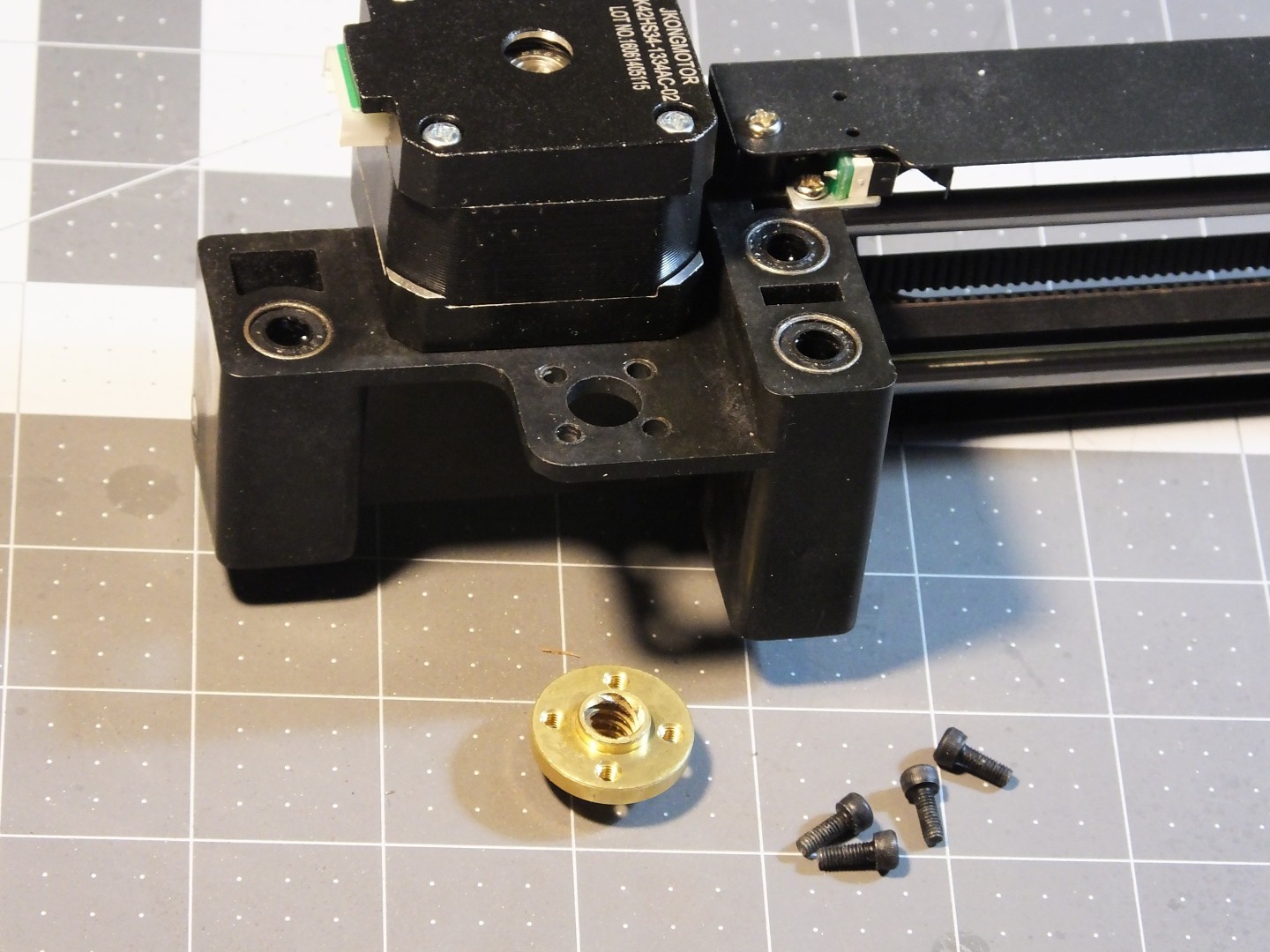
 The next step is replacing the lead screw nut on the X-axis gantry with the new one that came with the leadscrew. Take out the 4 screws from the existing nut and swap in the new nut. You will need some M3 screws to hold the new nut in place. Note that the nut can sit on top of or below the gantry. If you use a separate motor and leadscrew with a coupler, you will possibly have to put the leadscrew nut on the top of the gantry to leave space for the coupler under the gantry.
 You should have a printed NEMA17 mounting bracket for the Z-axis already printed and ready to install. If not, grab the file from our Thingiverse page here: http://www.thingiverse.com/thing:2199805 and put your mini back together and print it out. ;-) The bracket plastic doesn't matter (as long as you don't use flexible filament) because it should not get too hot. You will want to use thick (>1mm) walls and top/bottom with heavy (>25%) infill to make sure this part is stiff and does not flex. Be sure it is not warped when you print it too. It has to be perfectly flat.
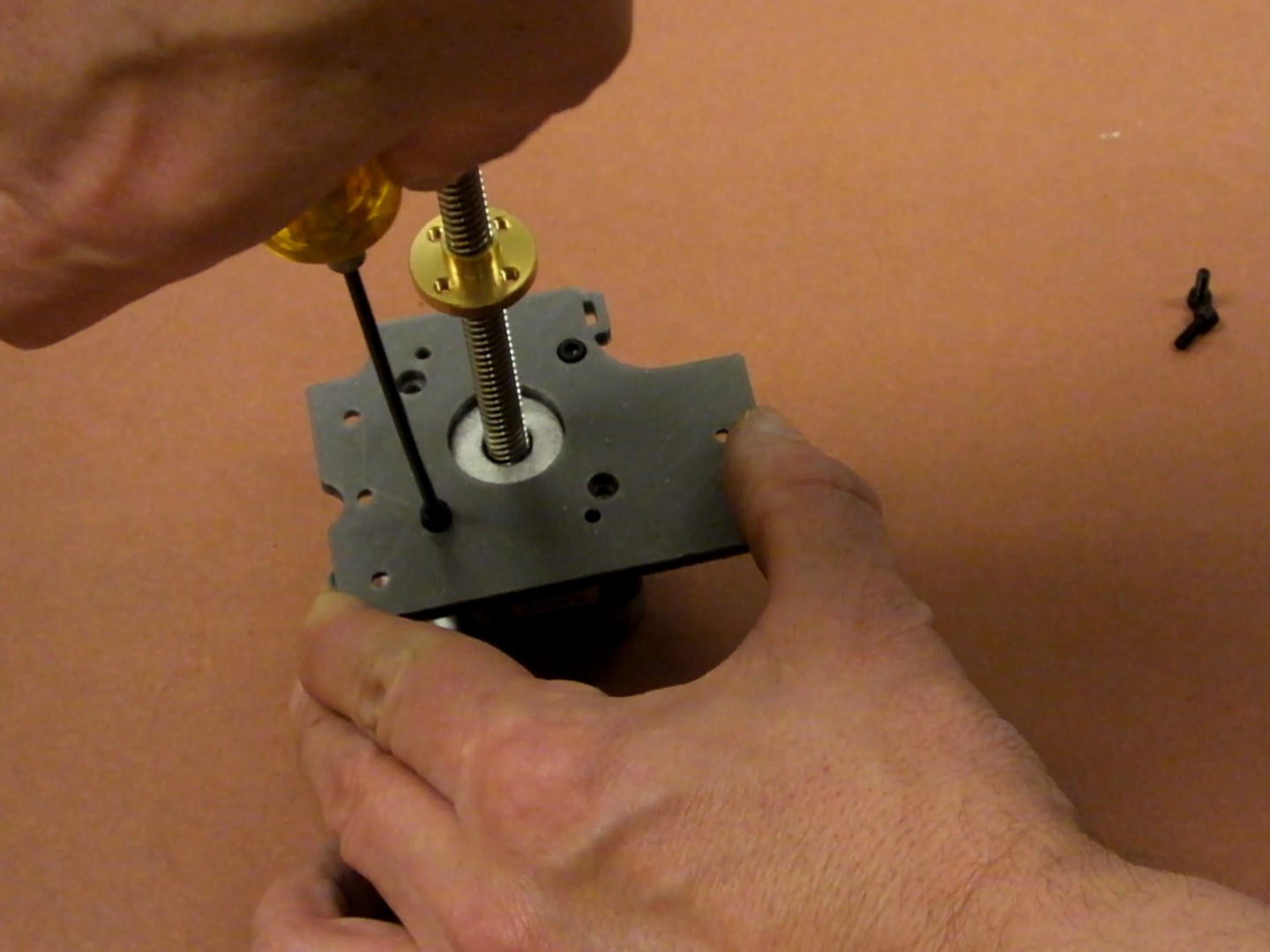
 The bracket mounts on top of the NEMA17 motor and has recessed countersunk holes for four M3 socket cap screws. The bracket only works in this orientation, so be sure the screws are in the countersunk holes and are not bottoming out in the motor. They screws have to be secured to the plastic so the motor cannot move. Different motors seem to have different depth threaded holes so try a few screws until you find ones that don't hit the bottom of the holes in the motor.
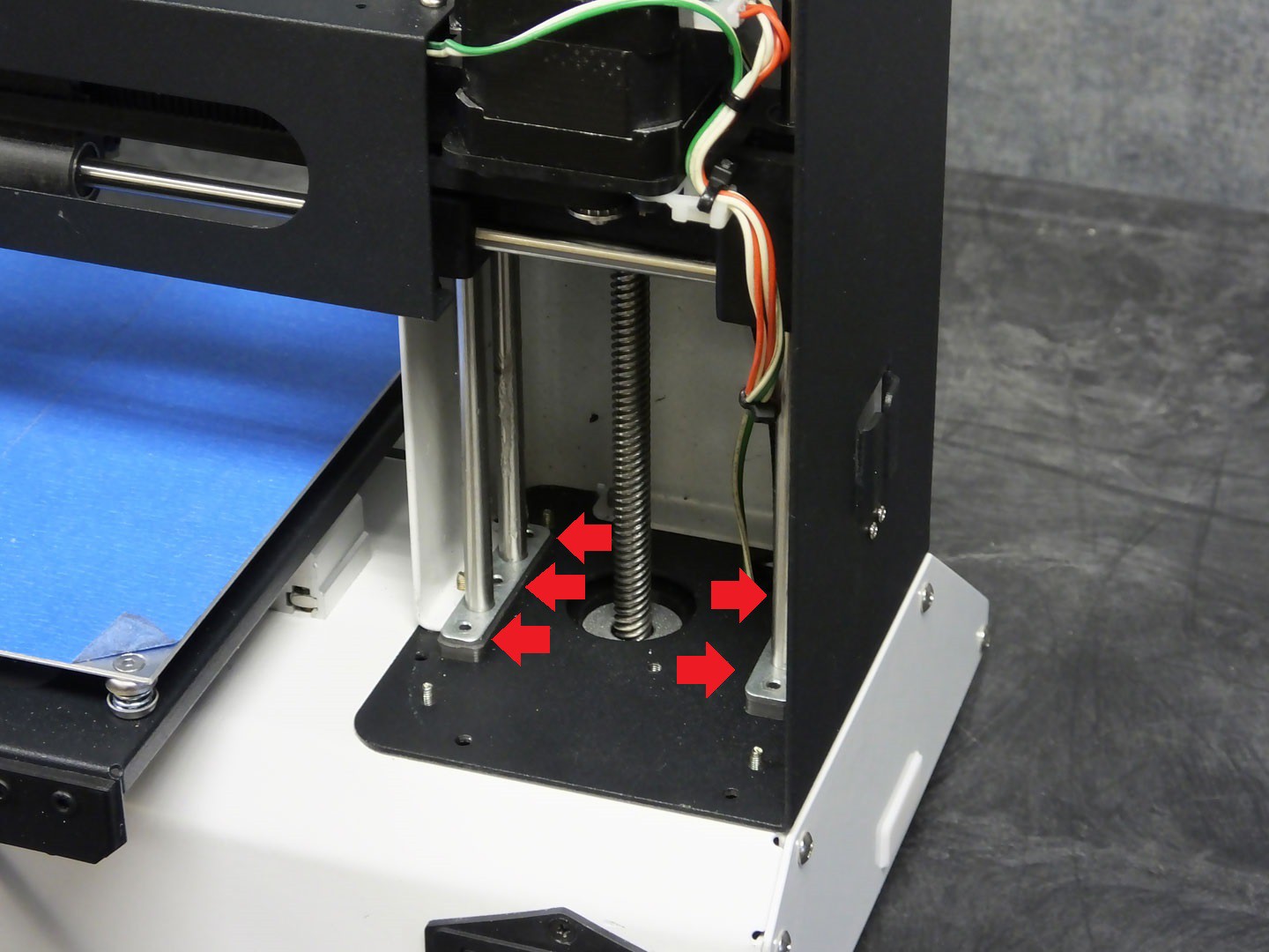
 Reassemble the Z-axis rods and X-axis gantry as described in the "Z-axis stabilizers" part of this project, and insert the NEMA17 motor into the chassis from below. Do not install the screws in the Z-axis rod ends shown here with red arrows just yet. You will also need to start the leadscrew threads into the leadscrew nut on the gantry and turn the leadscrew by hand until the NEMA17 motor can slide in place without the gantry hitting the upper extent of travel.
 You can now install the screws through the motor bracket and into the z-axis rod stabilizers, holding the rods and the motor to the chassis and also in perfect alignment to each other. You may need slightly longer screws for this as the screws now need to go through the motor bracket.
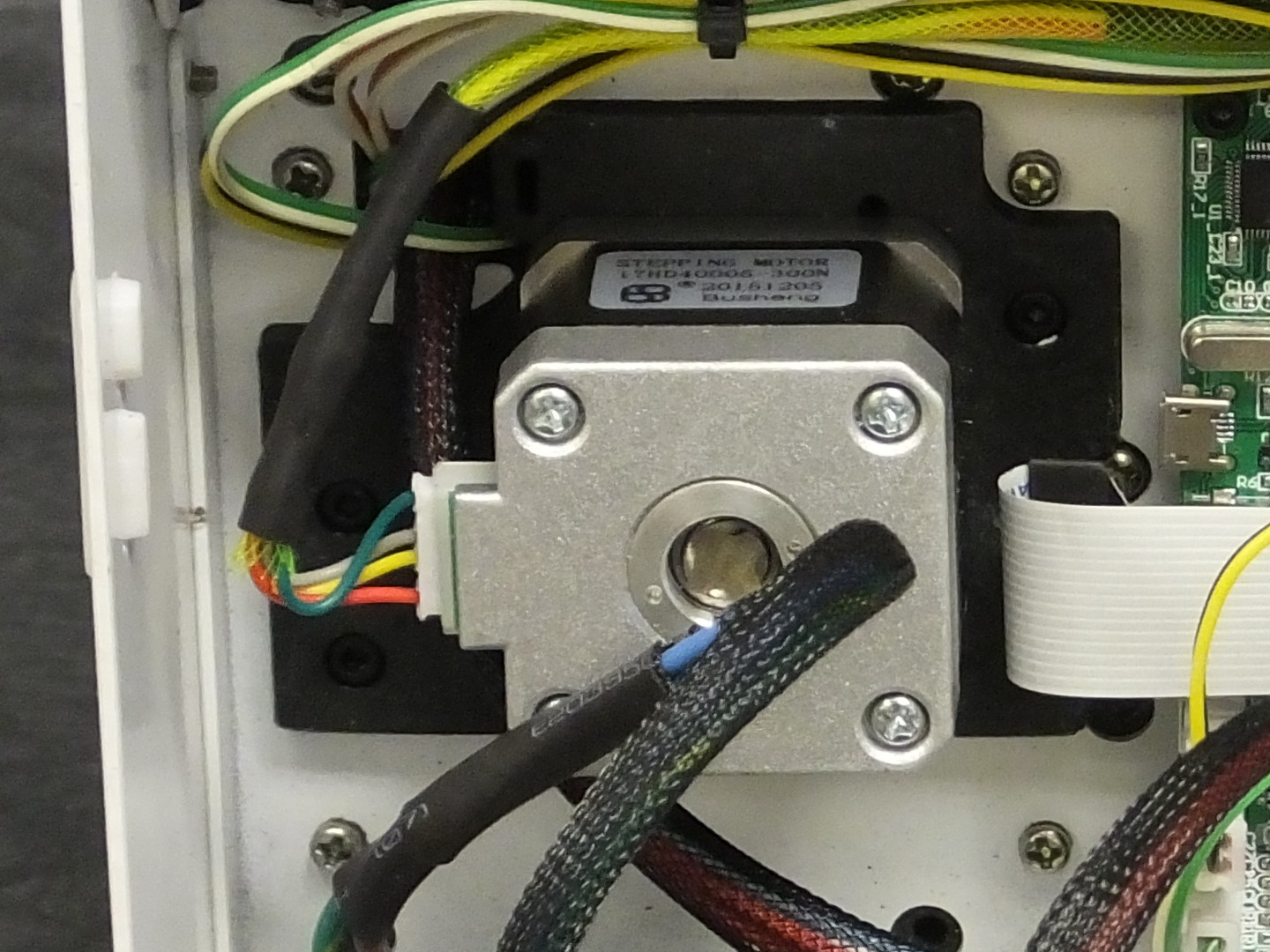
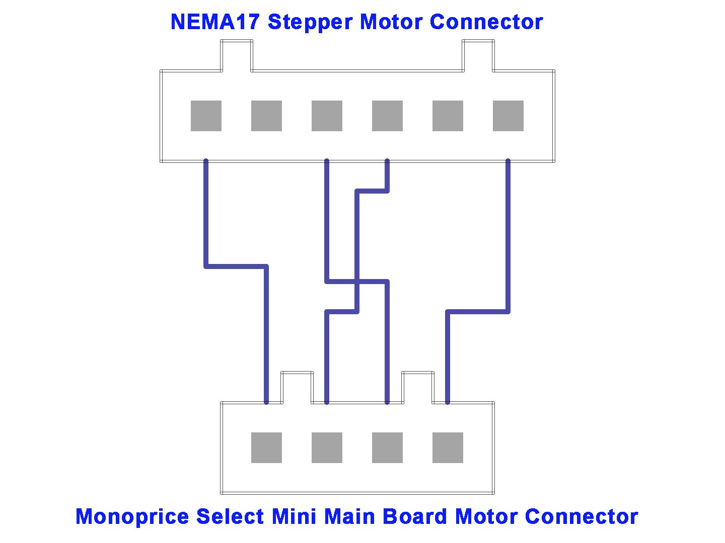
 The last thing you need to do is wire up your motor. If your motor has wires connected directly to it, you may have to do a little digging around the MPSM facebook Group to find out the correct way to wire your motor. I picked a motor with a cable that plugs in so that I could use the cable that came with the printer, only I was surprised to find out that the old motor and new motor had different plugs. Fortunately, the NEMA17 motors in the printer did have the same plug as the new NEMA17 motor. The only odd plug was on the old Z-axis motor. I simply took off the cable going to the Y-axis motor in the mini, and used that as a model to copy when making the cable for the new motor. All I did was cut the plug off the old Z-axis cable and spliced the wires to the cable that came with the printer in the correct locations. It worked!
 At this point, you should be ready to test the new motor and then configure the main board with the new motor parameters. To test the motor you can just power up and use the "move" menu to move the Z-axis up and down. The motor should rotate freely and raise and lower the gantry without hitting anything. If all is good, you can reassemble the covers on the printer and move on to calibrate the board to the motor.
Calibrating the printer CPU for the new motor is easy, and you must do this or the size of your prints will be way out of whack. I used the calculator at www.prusaprinters.org/calculator to find out the correct steps per millimeter for my motor and lead screw combination. I know from the seller that my motor is a 1.8 degree (200 steps per revolution) motor, and the printer can do 1/16th microstepping. The leadscrew thread pitch is 8mm per revolution, and the motor has no gearing, so the ratio is 1:1. Plugging those numbers into the calculator gives me a result of 400 steps per millimeter. The calculator even nicely reminds me that the G-code for this uses the M92 command (but it does have a type where it calls this out as the X axis).
All that's left to do is send this to the printer to tell it the new value for Z steps per mm and we're done. The easiest way to make this happen is to open up a text editor and create a text file and stuff the commands into it and then save it as "xxxx.gcode" and take it to the printer and print "xxxx.gcode" (use any name you like in place of xxxx.gcode). The printer will read the settings and configure the printer accordingly.
The file I used looks like:
M92 Z400 ; Configure Motor
 M500     ; Save New Settings
 G28      ; Home All Axis
 M84      ; Disable All Motors
That's it!
-
Major Upgrades Begin Here!
03/24/2017 at 00:41 • 0 commentsAt this point we've gone about as far as we can to make the stock MPSM as good as we can on a shoestring budget. At this point we want to do some more extensive modifications but we still want to keep the price reasonable, so what we do will be low cost. We've just lifted the artificial cap of $199 for the printer and all mods combined which we self-imposed when we started.
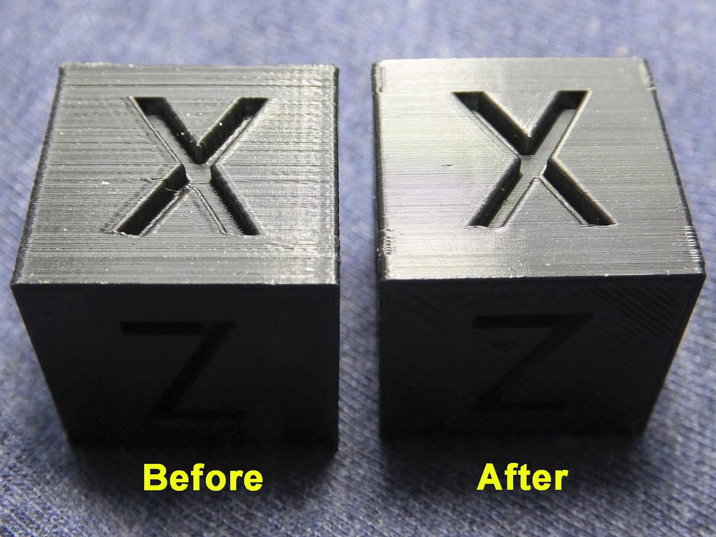
Over the past few months, we've done over 20 modifications to a second Monoprice Select Mini that we purchased on the used market. We've taken the stock mini and added about $50 in upgrades to it and as you can see from the photo below, we had spectacular results.
 This was done on the same printer with the same filament at the same cura settings (except for a tiny difference in layer height due to different Z-axis thread pitch). You can see what a difference it makes!
In the coming weeks, we will be releasing the files and instructions for these modifications, and will begin featuring some upgrade instruction videos on our YouTube channel http://www.youtube.com/USWaterRockets! We hope you can make use of these upgrades for your own mini, or just to learn about making your own upgrades for another printer. Be sure and follow this project, subscribe to our YouTube Channel, and follow us on thingiverse at http://www.thingiverse.com/USWaterRockets where we will be publishing the files!
Enjoy!
-
Keeping the X-Axis Belt from Twisting
01/20/2017 at 05:17 • 4 commentsOver on the Facebook Group for the Mini, Brian Corbino started a flurry of activity when he posted a description of how he went about changing the plastic pulleys and cheap belts in the Mini with aluminum pulleys and GT2 belts. Quite a number of people were interested in this project, and have been having a lot of success with this upgrade.
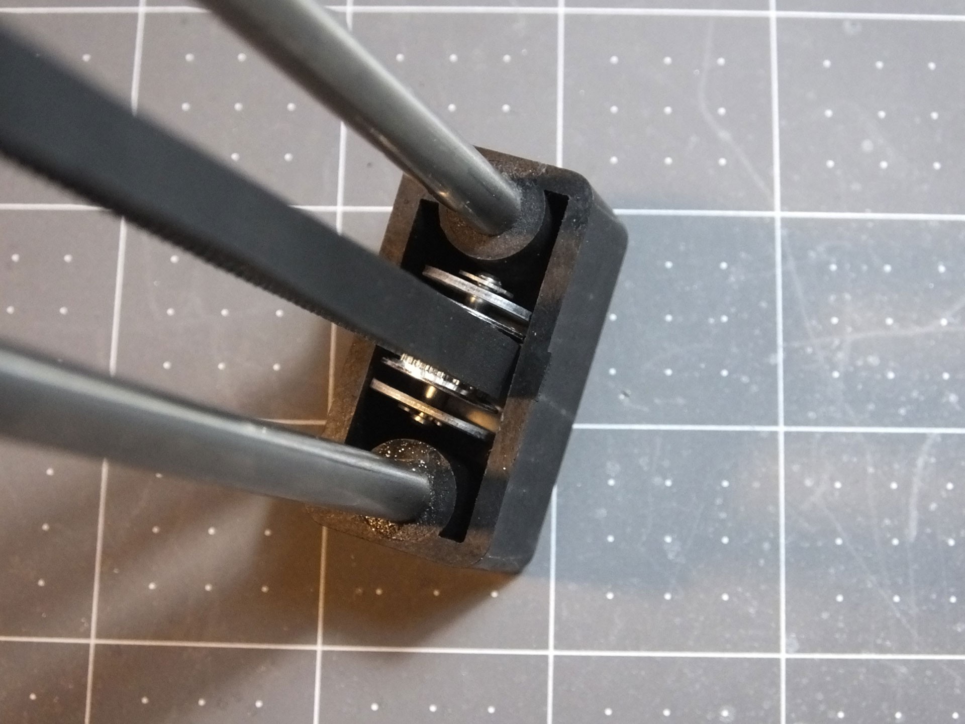
Seeing how many people are swapping the pulleys reminded me of something I wanted to fix on the Mini for a long time but never got around to it. What I'm talking about is the way the pulley bracket for the X-Axis idler pulley is fastened to the end of the gantry with a single screw on the center point of the bracket. This means that the pulley is completely free to twist out of alignment when you tighten the screw.
 See how the pulley bracket is twisted? This is really annoying, and every time you install this pulley you have to mess around and try and get it straight by hand. Because this annoys me, I created an Alignment Clip that goes between the pulley bracket and the plastic channel where the pulley sits, which keeps the pulley at a perfect right angle to the rods, which will make the belt perfectly flat and level.
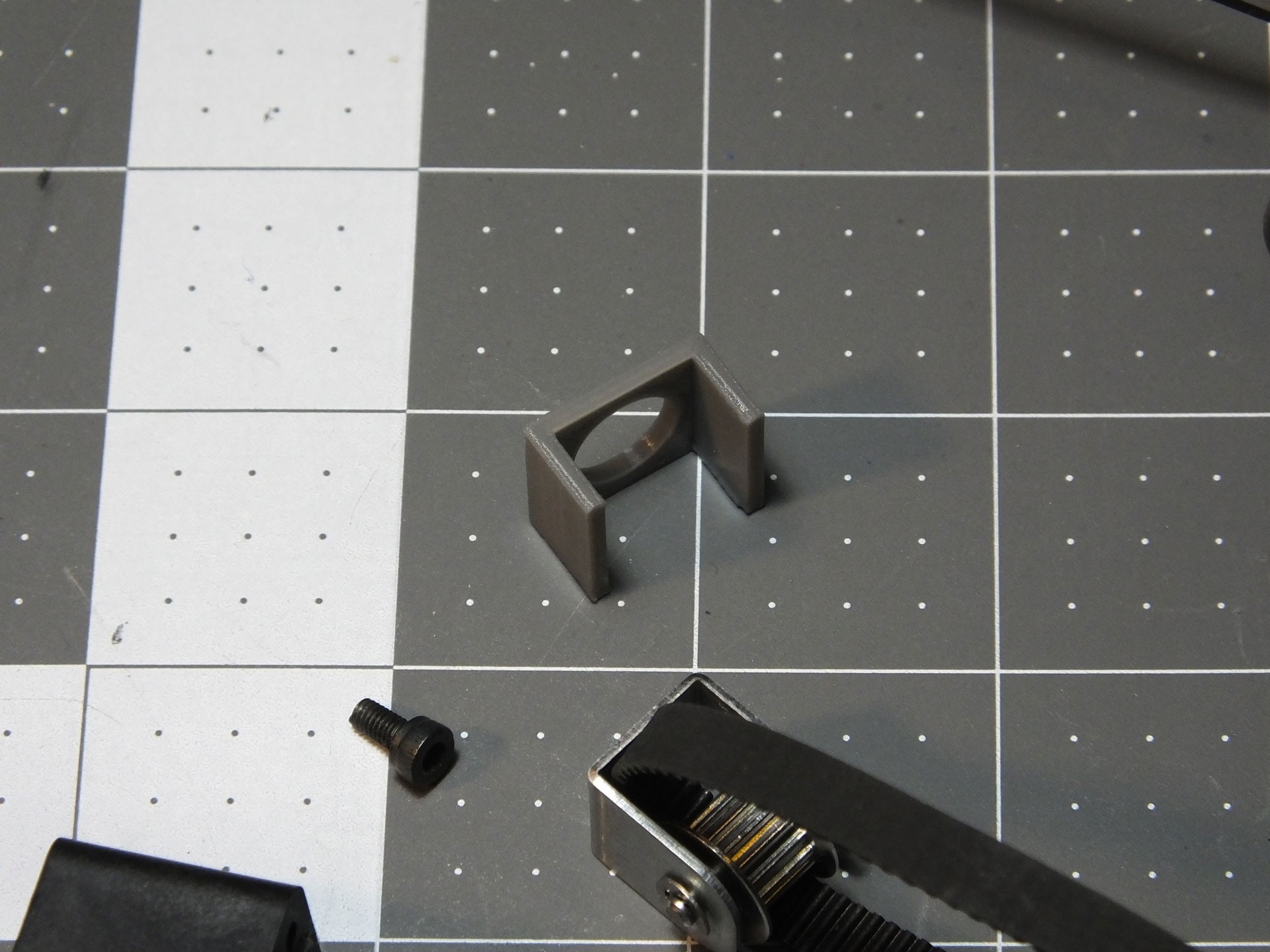
 Here is what the Alignment Clip looks like before it is installed. To install the alignment bracket, you can clip it over the pulley bracket and insert it into the channel in the end of the gantry, or put the Alignment Clip in the channel first and then install the pulley bracket. If you want to print your very own Alignment Clip, you can get the model from my Thingiverse Page: http://www.thingiverse.com/thing:2049820
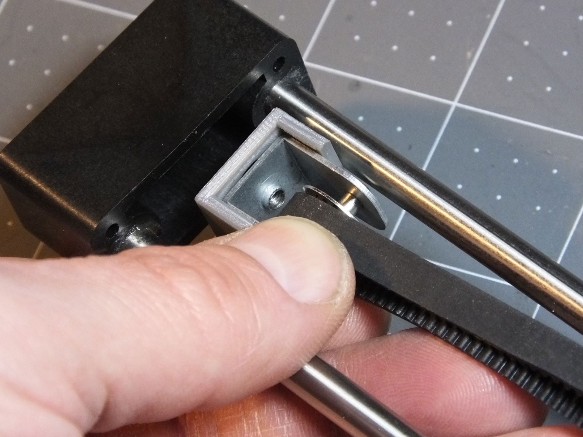
 Note the orientation of the Alignment clip. It should only clip on one way and should center itself once you install it on the gantry. It should fit snugly in the channel, and prevent the pulley from twisting.
 Here's the "After" photo, showing how nice and straight the pulley is now that it can't twist. Does this affect print quality or the life of the belt and pulley? I'm not sure. However, it takes only a couple of minutes to print, and makes working on the belt and pulley totally effortless. You don't have to fuss with the alignment of the pulley by hand any longer.
 -
Don't go wobbly on me now!
01/14/2017 at 23:02 • 0 comments Several people in the Facebook Group for the Monoprice Select Mini have experienced severe issues with wobble in their Z-axis that is not cured by stabilizing the rails. I have seen several people who have observed that their print quality suffers because the stock coupler between the Z-Axis Stepper Motor and the Threaded Rod is not aligning the two shafts properly, or the grub screw is shifting the rod to one side. I decided to make a replacement for the coupler that forces the threaded rod into perfect alignment with the motor shaft. Get the file on my Thingiverse page: http://www.thingiverse.com/thing:2038369
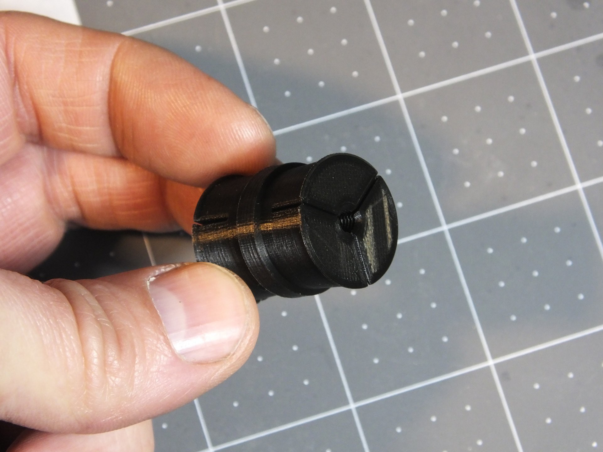
 Here is the coupler which I designed. On one side it has threads for the 4mmx0.7 Threaded Rod, and the other side has a hole to accept the 3mm Motor Shaft. Three clamping surfaces per side will be used to hold the coupler firmly in place and force the two shafts into perfect alignment.
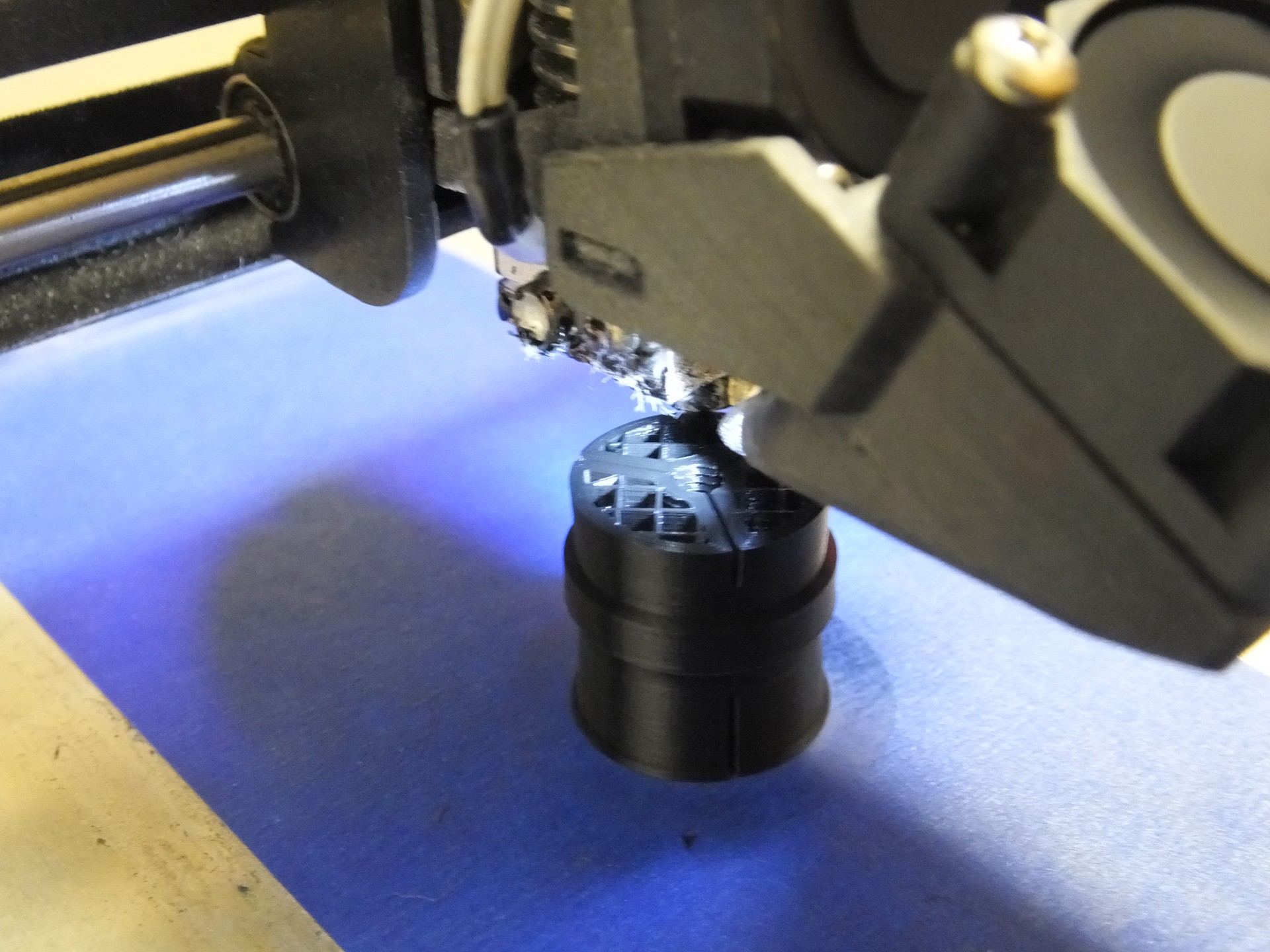
 This piece will print perfectly fine with no supports and oriented so that the threaded hole is facing up. Please print with thick walls and a decent fill. I used 4 perimeters and 20% infill for this one. I do not think the plastic type is important because this part is not subjected to heat.
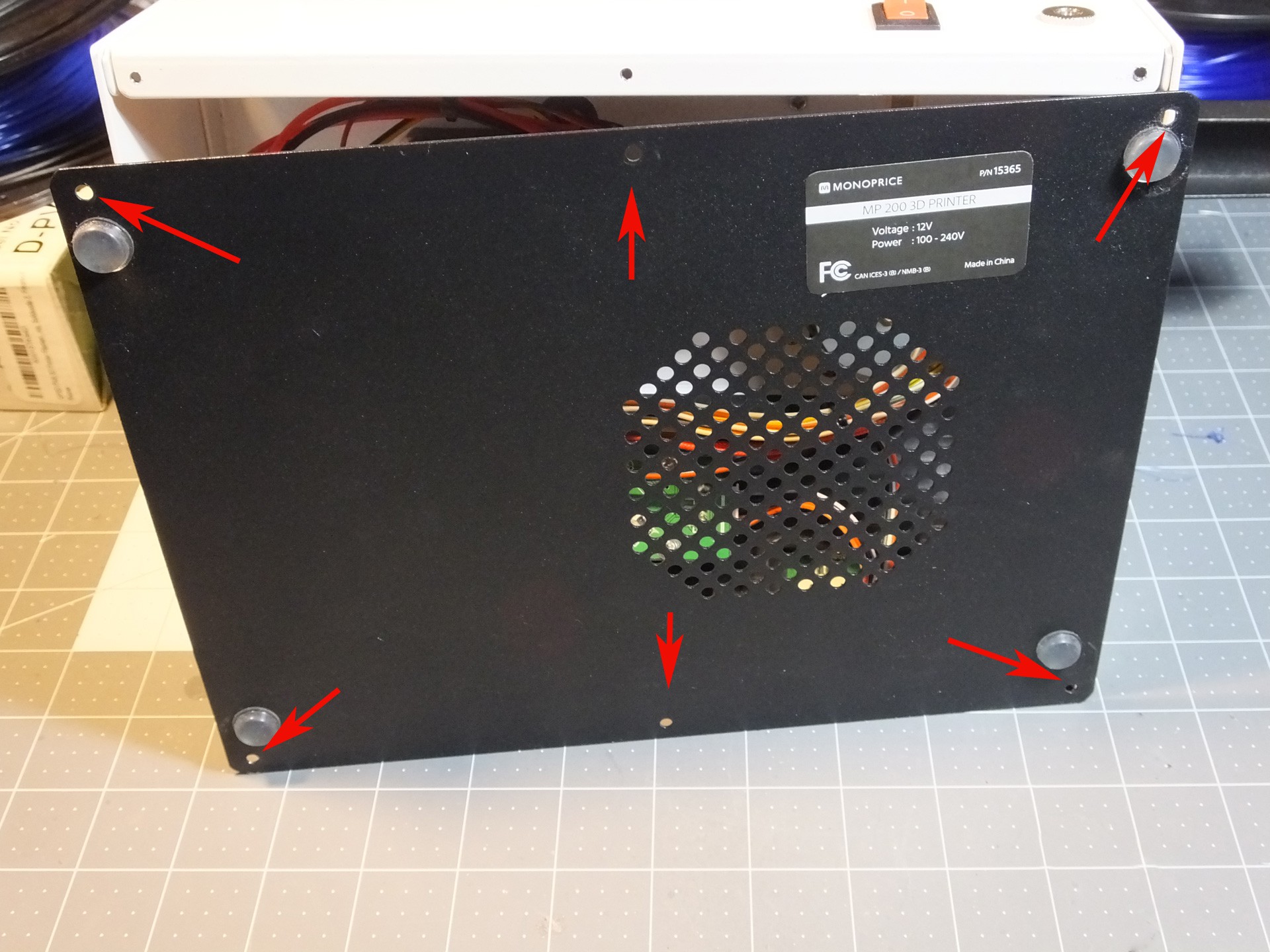
 Installation is very simple: Begin by removing the six screws that hold the black metal bottom to the mini and pull the bottom off the printer.
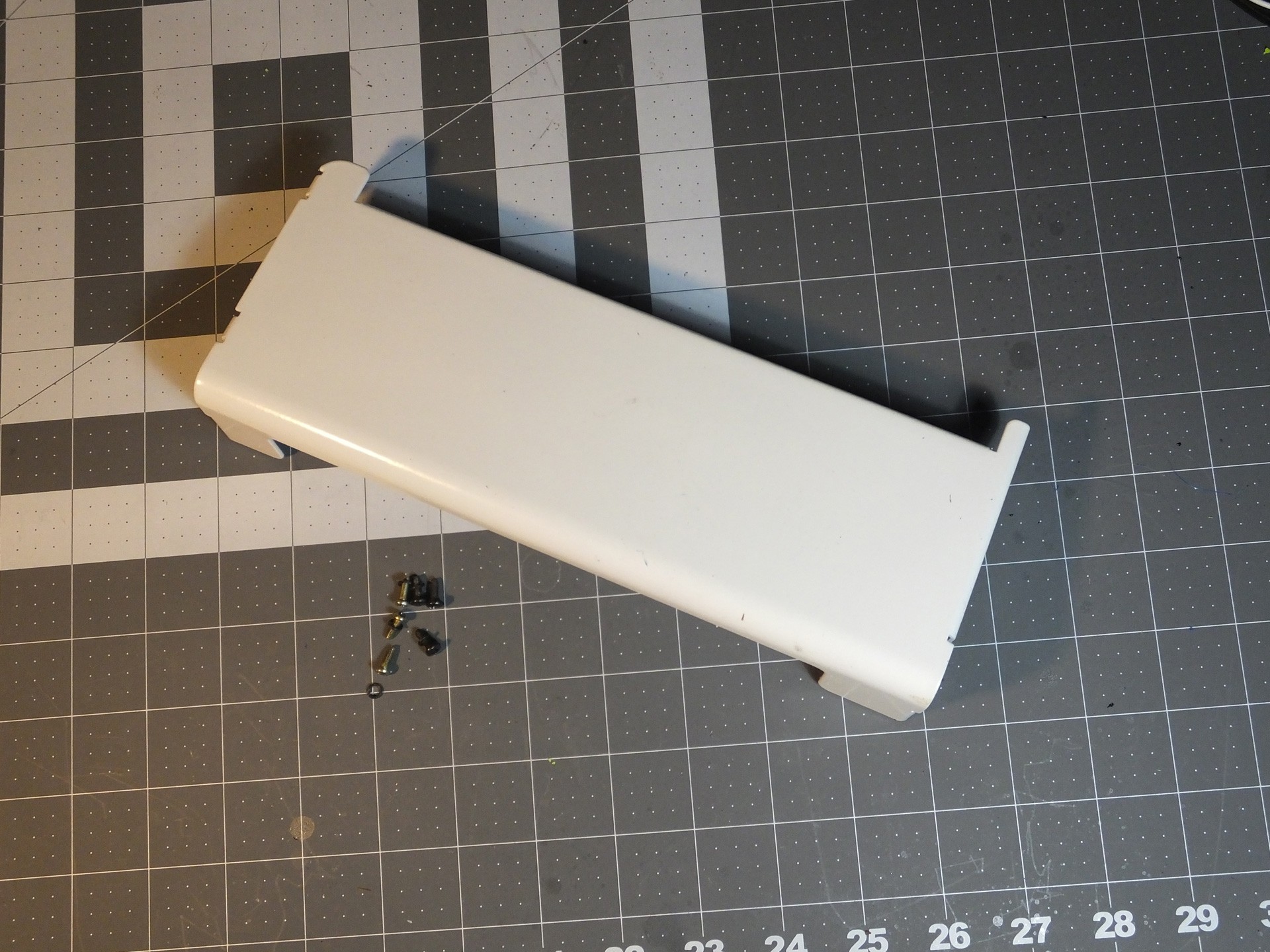
Six more screws hold the metal cover to the back of the tower, three on top and three inside the base of the Mini. These screws may have small washers on them, so keep track of the screws with washers and where they were located.
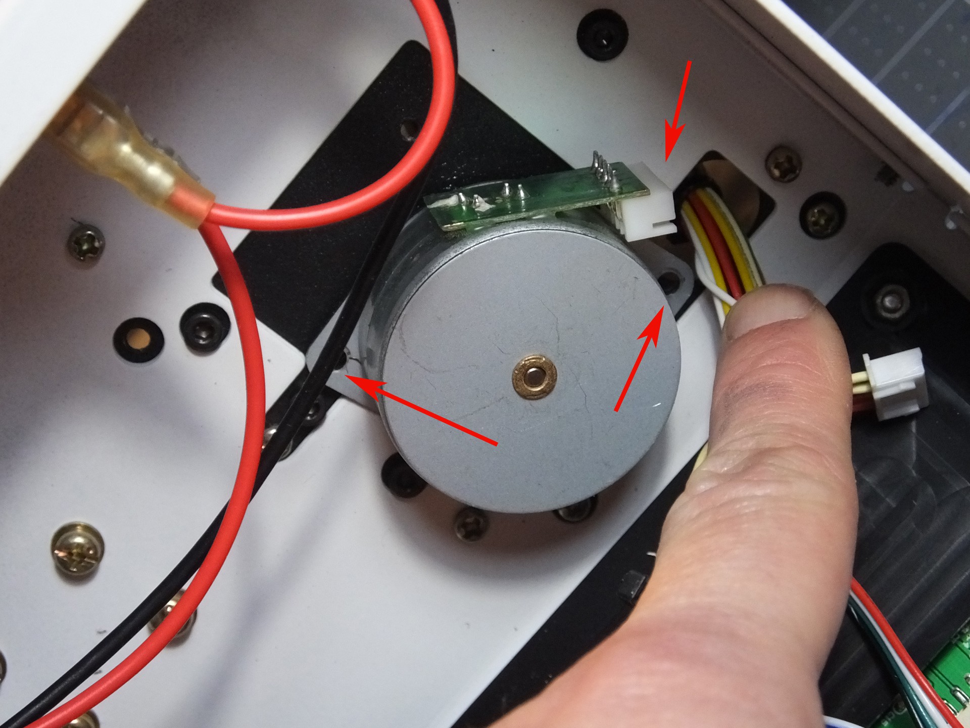
 Remove the two screws holding the Z-Axis Stepper Motor to the underside of the tower. Also unplug the cable while you're in there. Note the position of the connector on the motor where the wires were plugged in. When you put the printer back together, you have a 50% chance of facing this in the wrong direction, unless you make a note this position now.
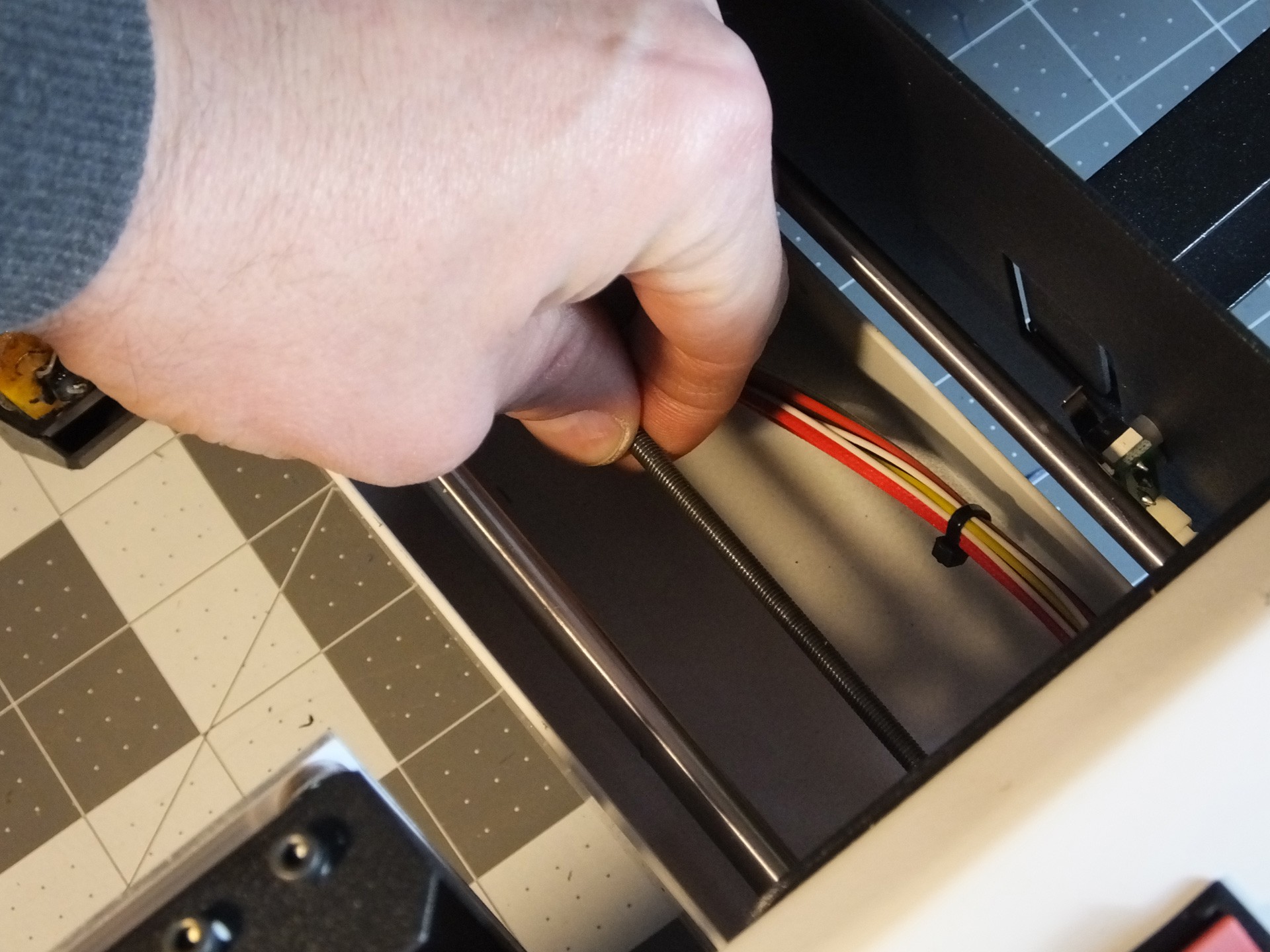
 Spin the Threaded Rod to unscrew it from the Gantry. If you are reading these instructions before you began working then you get a bonus! When you begin work use the move menu to raise the Gantry all the way to the top before tearing down the printer. It will save you a lot of spinning of the Threaded Rod in this step here.
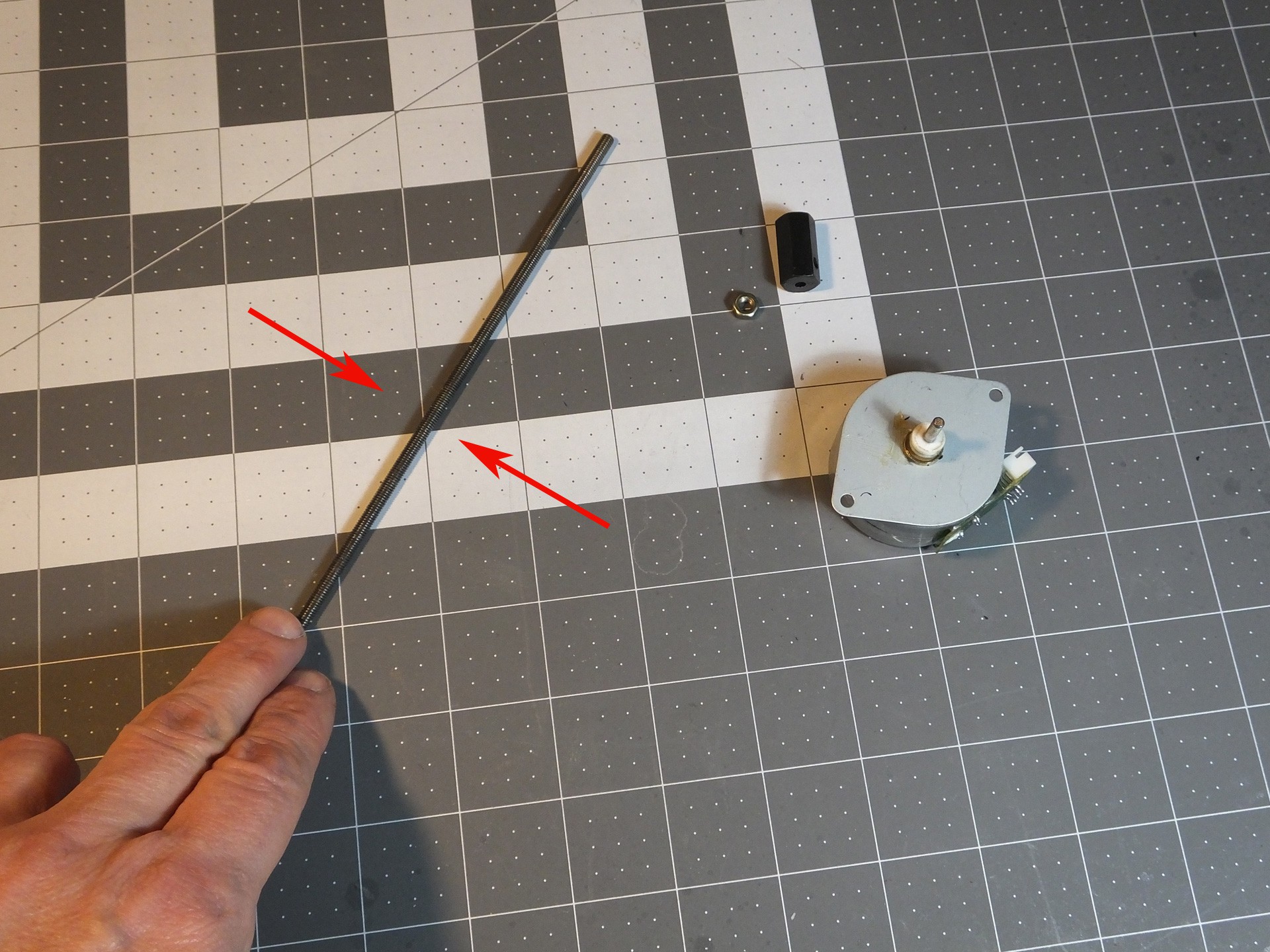
When you've unscrewed the Threaded Rod from the Gantry, it will come right off with the Stepper Motor. You need to remove the factory coupler from the Threaded Rod and the Stepper Motor, by loosening the grub screw or screws in the side of the coupler. There are often locked in place with a threadlocker, so use a flame from a lighter to heat the coupler very hot and the threads should come loose. Just be careful not to touch the hot metal. The coupler and the locking nut on top should come right off with a couple of wrenches now.

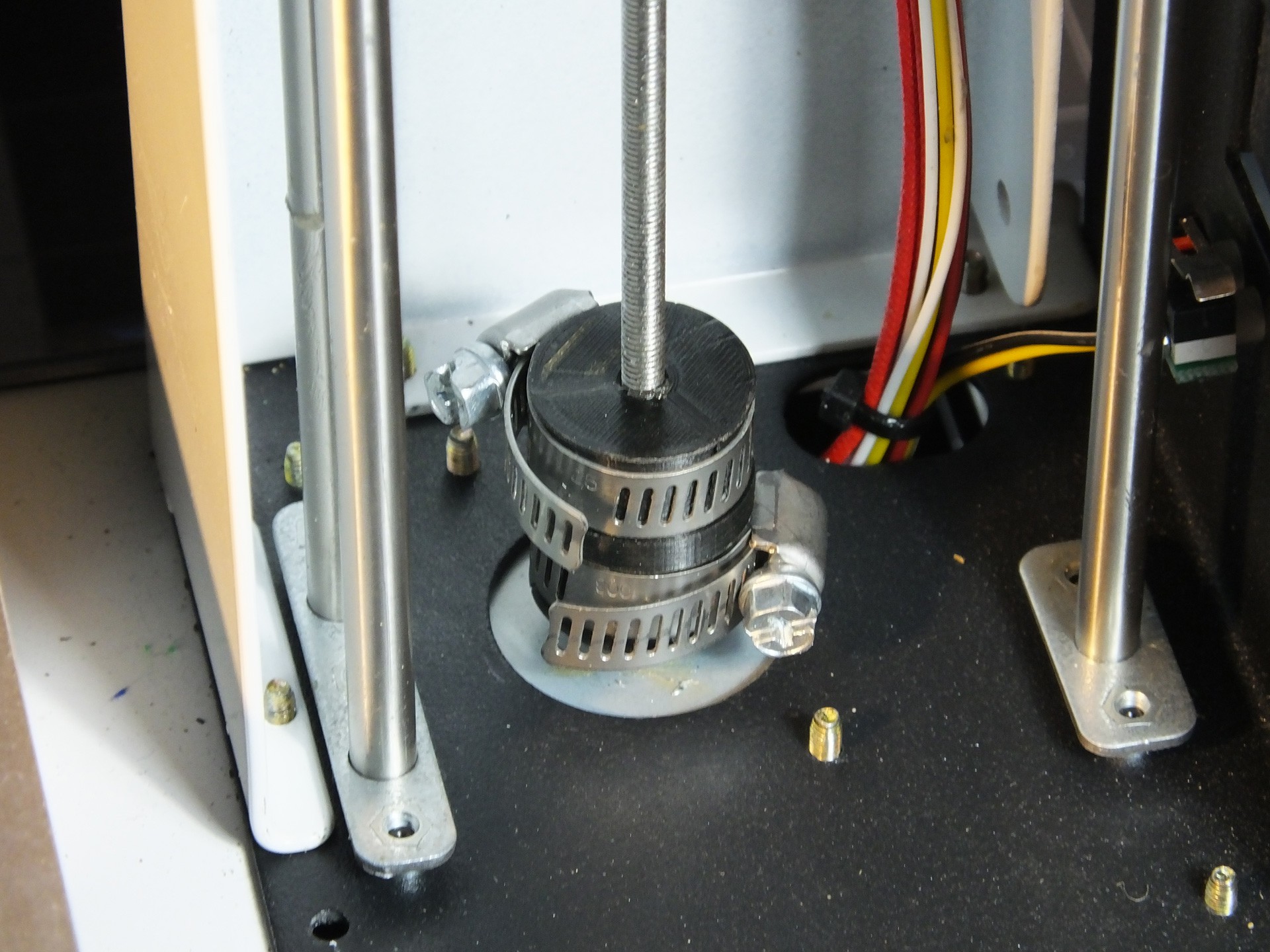
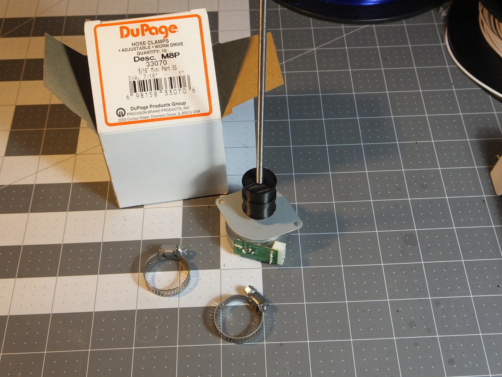
Roll the Threaded Rod on a perfectly flat surface and look to see if it is warped or bent. If it is, you can try to straighten it by hand until it rolls perfectly, or obtain a replacement part. Push the unthreaded side of the New Coupler on the Motor Shaft until it just touches the spacers on the shaft. If you don't have spacers, don't go any closer to the motor than about 5mm. Then, thread the Threaded Rod into the threaded side of the New Coupler, and tighten it until it reaches the bottom of the hole. At this point you want to get a pair of Hose Clamps ready. The Hose Clamps should fit a 1" pipe and have a 5/16" wide band. Slightly smaller clamps should fit as well. Just prepare them by opening them up wide enough to fit over the New Coupler easily. DO NOT INSTALL THEM YET. If you do, you won't get the Stepper Motor back on.
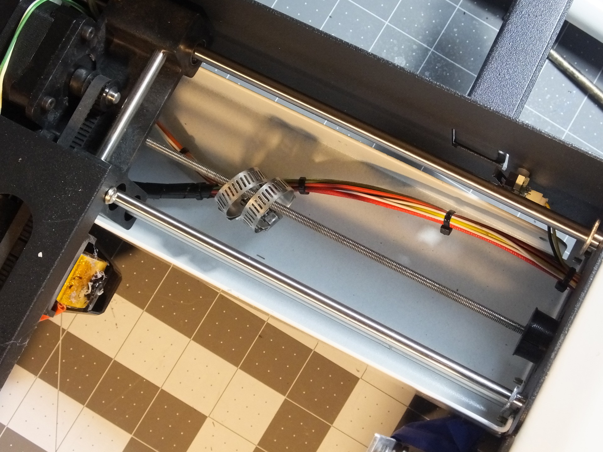
 Now, insert the Threaded Rod through the hole and slide the Hose Clamps over the rod before you start threading it back into the Gantry where you removed it. Keep screwing the Threaded Rod into the Gantry until you can seat the Stepper Motor back where it belongs and screw it back in place, making note to get the connector back in the right position to reach the connector on the wiring harness.
 Now you can slide the Hose Clamps down into the grooves in the New Coupler and tighten them up, to secure the Threaded Rod and Z-Axis Motor Shaft in perfect alignment.
Check that the clamps don't interfere with the wiring inside the tower. If you think they may snag, you can cover the clamps with Electrical Tape to prevent them from catching the wiring.
Reinstall the rear cover of the tower, and then put the bottom cover back on the printer.
This upgrade cost me about $1.00 total, for two hose clamps. That's it!
Happy Printing!
-
I have the Power!
11/09/2016 at 18:11 • 7 commentsOkay, so I screwed up. I was attempting to measure the power consumption of the Mini by putting a power resistor inline with the power supply and computing the power from the voltage across the resistor. That was the idea, but I was lazy and used clip leads to tap into the power at the barrel connector of the Mini, and I shorted the power supply by accident and it died. I should have opened the printer and tapped into the power wiring inside, but I was in a hurry because I wanted to get back to a big printing project and in my haste I killed the power supply. Thankfully, the Mini itself was fine when I tested with a benchtop supply. I only killed the power supply.
The idea of using a bench supply every time I used my mini was bugging me, and I had seen other people replacing the supply and relocating it inside the Mini before, so I decided I would try to make an internal supply mod for my Mini as well.
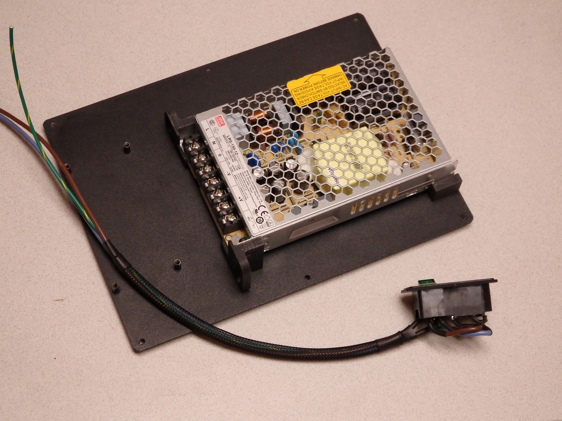
I hit the interwebs and tried to find a power supply that was small enough to fit inside the Mini, but had better specs than the stock supply. I wanted something with more current, so I could further mod the Mini and not run into power supply loading issues. The stock power supply is supposed to provide 10A of power at 12VDC, so the stock supply should be rated for 120 Watts (10A * 12V = 120W). By picking a higher capacity supply I would also be running it below spec and it should stay cooler as well. I settled on using a Meanwell LRS-150-12 supply. These are 150W at 12VDC, and sell for about $20 online, and my measurements indicated it would fit inside the Mini case.
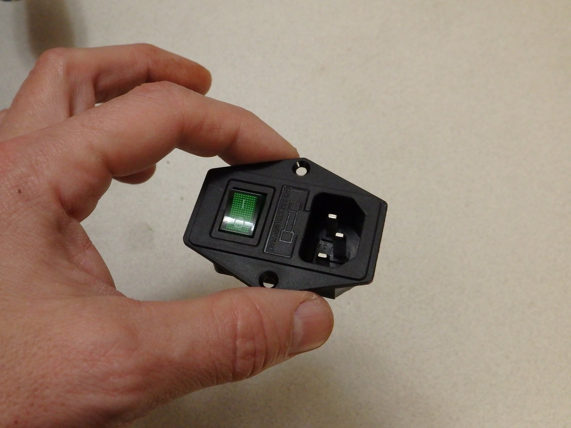
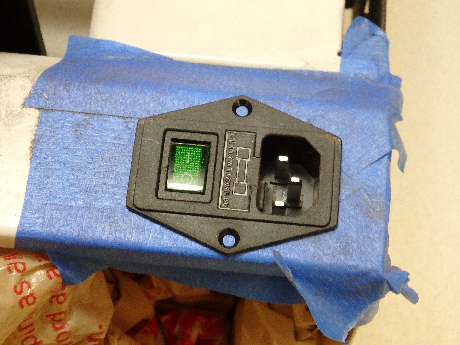
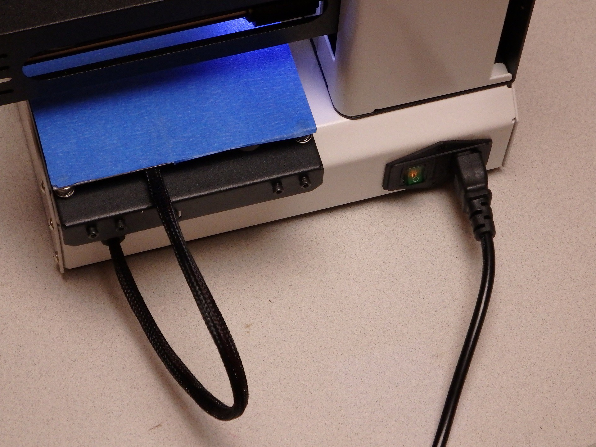
While I was messing around with the power supply, I decided I would add a switch and a fuse and when I was looking around I came across a nice little IEC320 C14 Power Socket with Illuminated Switch Fuse Holder on Amazon (Search for the part by name and several sellers come up). I did some measurements, and determined that the socket would fit in a hole that completely covered the existing power input and switch holes in the Mini, so it would look like it was a factory installed component.
When I got the power supply I test fit it inside, and there was plenty of room. However, the supply covered the vents in the bottom of the case. The height of the supply is short enough that I decided to raise it up on metal threaded standoffs so that it would have ventilation under the supply. The problem with this idea is that there are only two mounting screw holes on the bottom of the supply. The holes are on opposite corners, so they could hold it in place, but it seemed a little unstable for my tastes. I ditched the standoffs in favor of some printed mounting brackets that would hold it in more than two points.
While my mounting brackets were printing, I wired up the input wiring. Based on the test fitting of the power supply, I opted to directly solder the power wiring to the lugs on the power socket and switch, instead of using crimp on spade terminals. This allowed me to better insulate the wiring with heat shrink, and bend the lugs over to provide extra clearance behind the power supply. This is how the power is wired for use with US 120VAC power.
My printed mounting brackets hold the supply on the bottom edge and side edges and provide attachment on all four corners, I also added some wire harness guide loops to assist in routing the wiring inside the Mini. I tweaked the size of the brackets for maximum clearance for the cooling air to come in through the vent holes below the power supply, and split the one bracket into two sections so there would be an air passage to flow from the vent to the CPU board. You can download these bracket files from our Thingiverse page at the following link: http://www.thingiverse.com/thing:1881464 (see that page for printing instructions)
When installed, they held the power supply firmly in place and had plenty of air gap over the vents to allow cooling air flow under the supply. I turned out great. The edge of the supply with the screw terminals just fits under the Z stepper motor, so I had to be careful where I located the supply mounting. In the end I found a location I was happy with.
Cutting a hole for the Power Socket was simple. I just used a Dremel tool with a cutting wheel. The steel was a lot thicker than I thought it would be, but working slowly and putting tape over the areas I wanted to keep pristine helped. I also stuffed plastic bags inside the Mini case, to prevent the dust and shavings from getting on the mechanism or electronics.
The sharp edges were cleaned up manually with a file and smoothed to the point I was happy they looked decent, then I test fit the Power Socket. The final bit of this work was finished up by drilling the mounting screw holes. I used some M3 flathead screws and nuts in the bracket to hold it in place.
When everything was buttoned up, the only thing I needed was a fuse for the Power Connector (It didn't come with one). I have seen where many people had the same issue with this connector and they ran out and ordered a fuse to match the current rating of their supply, but this is wrong and dangerous. A 10A 12V supply does not require a 10A fuse on the AC input side of the supply. You would use a 10A fuse if you were fusing the 12V lines. In the case of our Power Connector, the fuse is wired to the AC input, which has a significantly higher voltage, therefore the current needed is lower. I couldn't find the complete specs for the power supply, so I measured the AC current draw of the Mini with both heaters running and measured 2.6A on the AC input. I put a 3A fuse in the socket and it didn't blow. The inrush current of the power supply caused by turning the switch on and off didn't blow it either, so I think I have a good value for the fuse.
I'm really pleased with the way it turned out. I just completed a 56 hour long print with the Mini, and it worked flawlessly. I really like this mod. It did kind of blow up my budget on this project because it ended up costing about $25, but I think it looks really nice, and of course it frees up space on the desk by eliminating the bulky external supply. The added safety of the fuse is also a bonus. let me know what you think of this mod in the comments section. Enjoy!
Stay tuned for more mods!
-
What to do if you're not a fan of constantly running fans?
11/02/2016 at 18:50 • 3 commentsI'm not a big fan of having the cooling fan for my hot end running all the time, or having the LEDs on my hot end running all the time, I also wanted to add a cooling fan to my control board inside the printer, but I did not want to have that fan running all the time either. Other printers solve these issues by using software controlled outputs to turn these various peripheral devices on and off only when the printer is printing. I wanted to do something similar, but because the firmware of the printer is closed source and there are no extra outputs on the board to use for this purpose, I had to add this function the old fashioned way: with a circuit hack.
The general principle for this hack is to tap into the heater power and use the operation of the heater in the hot end to turn on and off the fans and LEDs. This is not nearly as simple as tapping into the heater power and using it to operate everything, since the heater is controlled by the software and it is pulsed on and off for various time periods to simulate an analog signal. By varying the amount of time the heater is on over a specific time period, a more precisely controlled temperature is achieved. For example, if you turn the heater on for 1 second out of every 10 seconds of elapsed time, the heater would be getting 10% of the energy it would get if it was on constantly. Therefore, the heater would be about 10% as hot. This pulsing of a digital value to simulate an analog value is called "Pulse Width Modulation" or PWM for short. This prevents us from using the heater control directly to control our fans and LEDs because they would be pulsing on and off as the controller tries to regulate the temperature of the hot end.
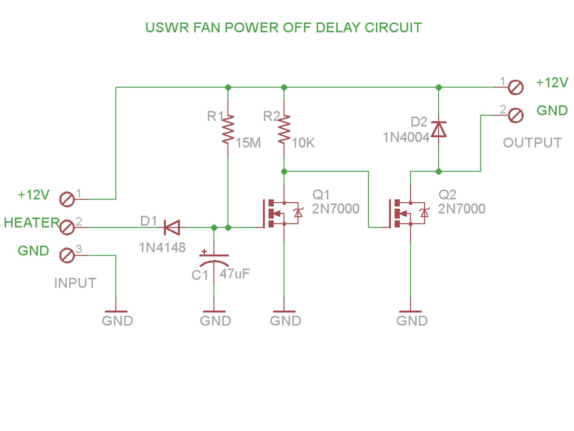
The solution to this issue is to create a circuit that is essentially a delay timer that will start counting when the heater is pulsed, and stops counting when some time has elapsed without activity on the heater. This is certainly a trivial thing to do with an Arduino, but we're going to do this the old fashioned way, with whatever scrap parts we have in the lab. Here is our circuit:
 The operation of the circuit is quite simple: 12V is provided to the heater and the ground for the heater is connected by a FET on the control board, when the heater is turned on. We use this signal to monitor for the heater activity.
When the HEATER signal is grounded (heater is ON), Capacitor C1 is discharged through Diode D1. This causes FET Q1 to turn OFF. This FET will stay off as long as HEATER is grounded. If HEATER is not grounded (the heater is pulsed OFF or shut down) then Capacitor C1 is charged very slowly through 15M resistor R1. Eventually, C1 reaches a point where it has charged enough to turn on FET Q1.
What we have in the circuit right now is that Q1 turns off when the heater is pulsed by the control board at least one time, and it stays off for about 2.5 minutes if the heater does not get pulsed again for that time. This is almost what we want. We really want the opposite logic. To fix this, we add a second FET connected to the drain of Q1 and configured as an inverter. 10K resistor R2 is connected to the gate of FET Q2 so when Q1 is on, it is pulling the gate of Q2 low and turning Q2 off. When Q1 is off, R2 pulls the gate of Q2 high, and turns it on.
Diode D1 is present to prevent leakage from the control board from charging C1 faster than we want, and diode D2 is present as a snubbing diode in case we power an inductive load with this circuit. D2 prevents the backflow of current when and load is shut off from damaging our circuit.
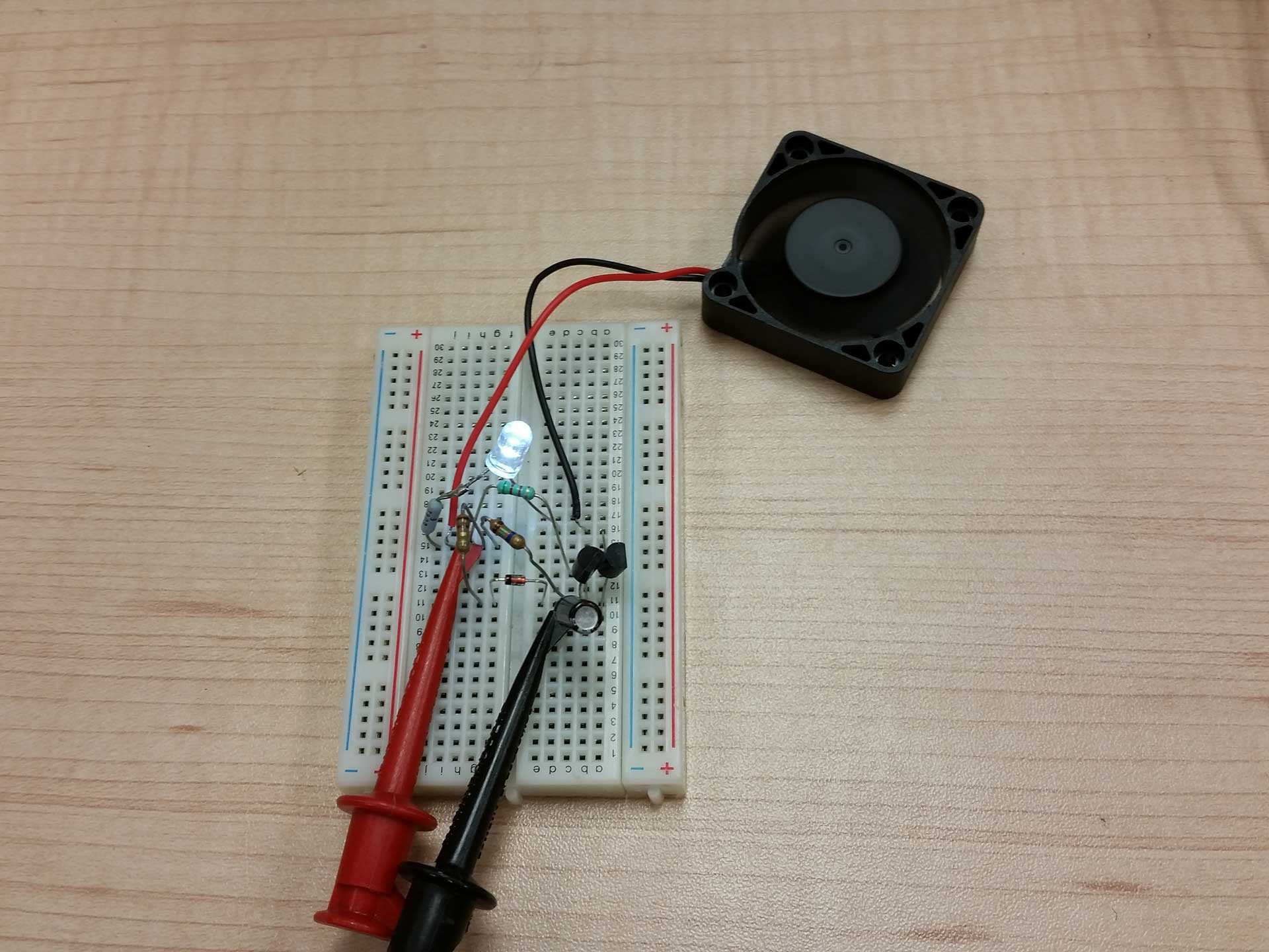
 The circuit was mocked up and tested on a breadboard kit, using through-hole parts I had not touched in a few years. It was fun going back and doing this for a change.
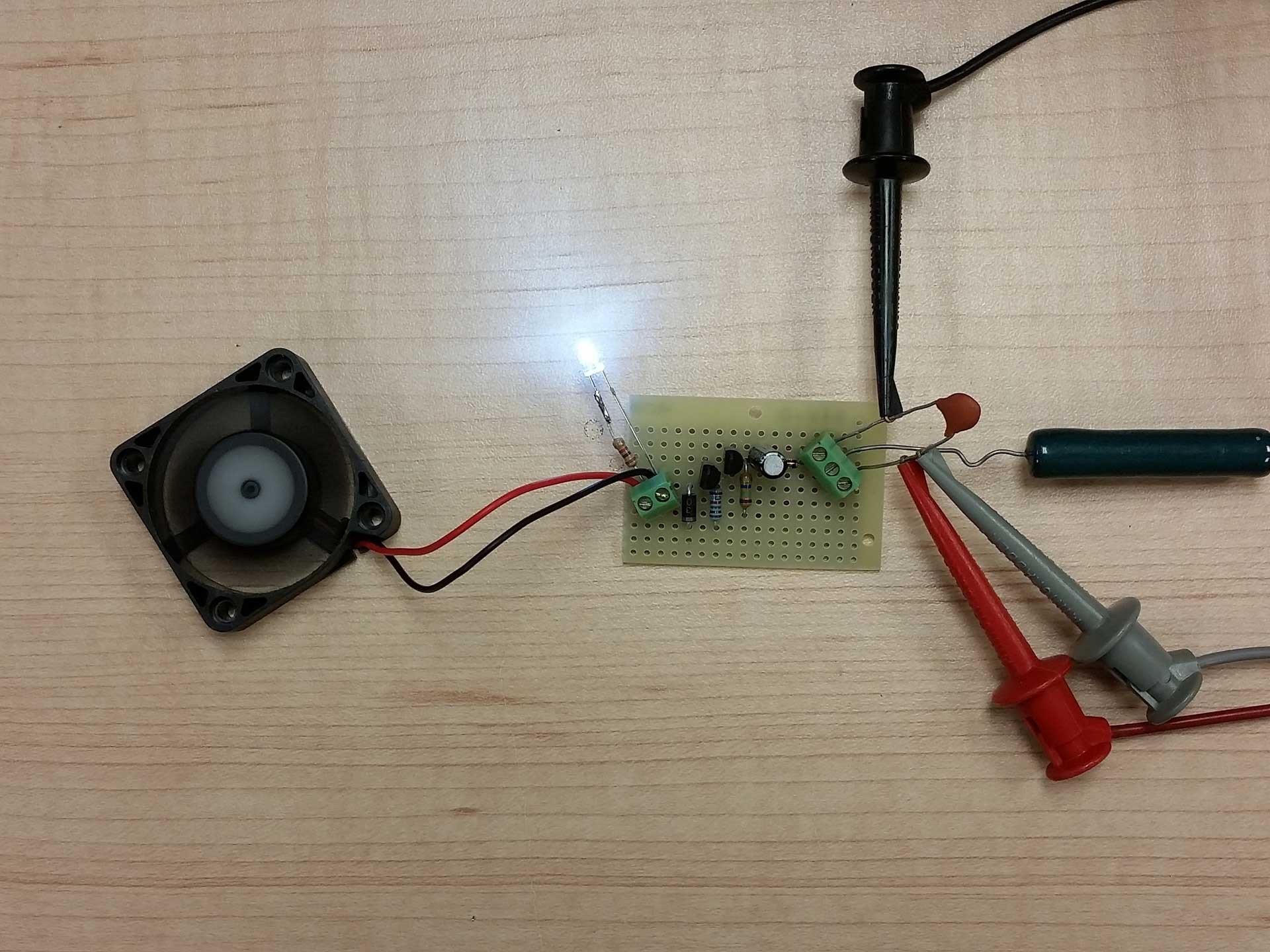
 The circuit was then transplanted to some perf board for installation in my Select Mini. Above you can see where I used an old wire wound 10 ohm resistor to simulate the heater. Grounding the center terminal on the right simulates the pulsing of the heater ground on the Mini. Another thing you may notice is the small capacitor on the + and - power terminals. This has nothing to do with the circuit itself. It's just a neat trick that a very smart guy told me many years ago. The purpose of the capacitor is to provide a place to clip test leads on the power screw terminals. Instead of sticking paper clips or wires into the screw terminals, you insert a capacitor (of sufficient voltage rating for the supply). The trick is that the capacitor doesn't affect the circuit but provides a good place to clip the test leads and the body of the capacitor prevents the leads from moving around and shorting together as you handle the circuit. I always loved this trick.
In the video clip below, you can see the circuit in operation.
If you view the video, you can see where I simulate a single pulse on the heater, and the LED and fan run for 2.5 minutes and then shut off. I chose the lengthy delay because I wanted to insure that when the printer finished a print, the cooling fan would continue to run for a long enough time period to allow the nozzle to cool off. I chose 2,5 minutes based on how fast the stock hot end cooled.
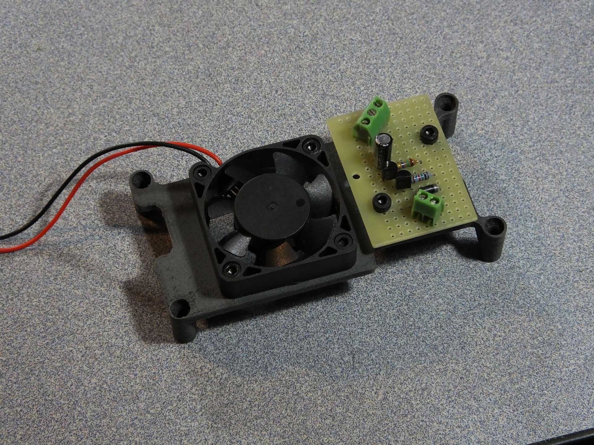
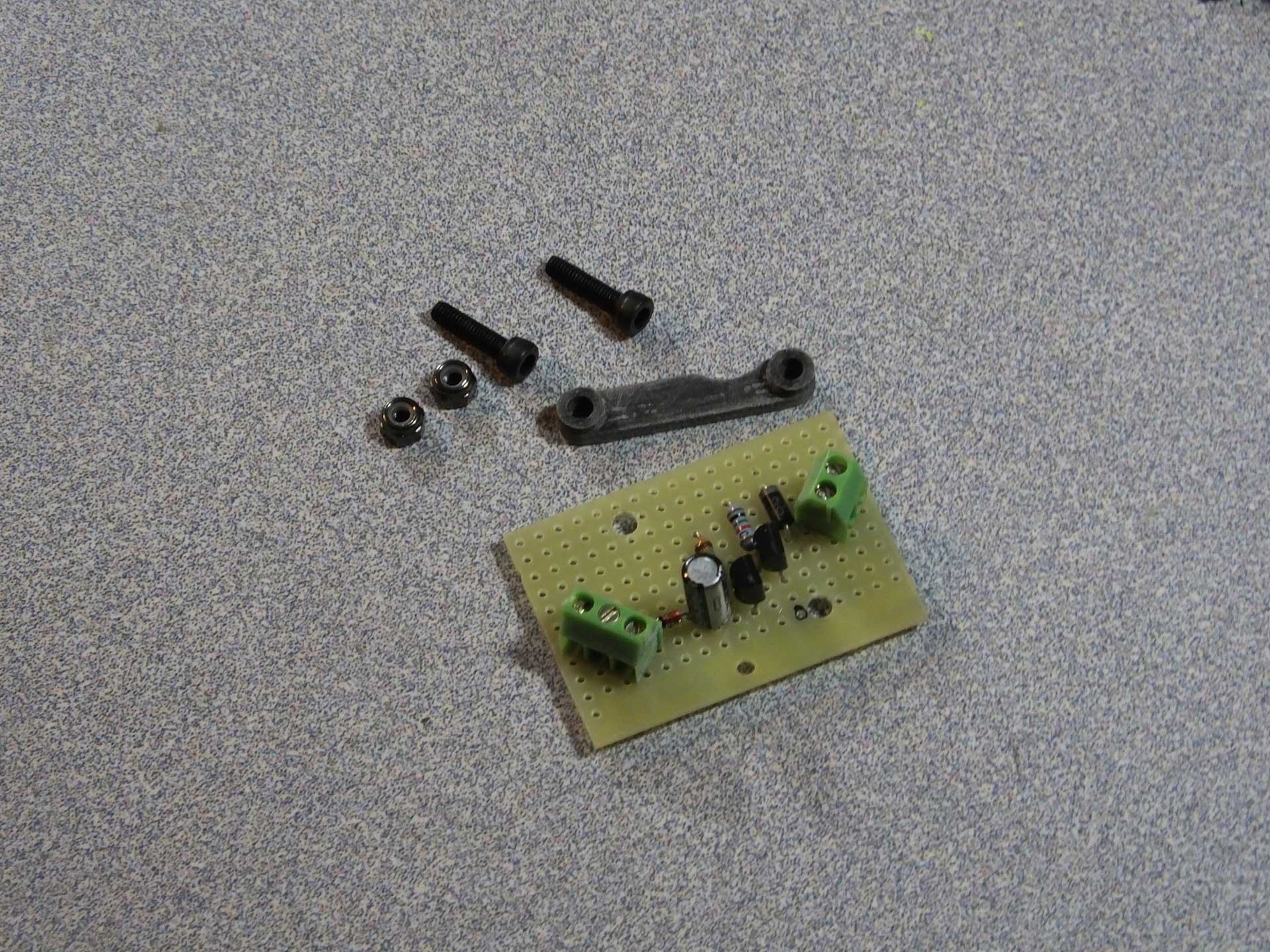
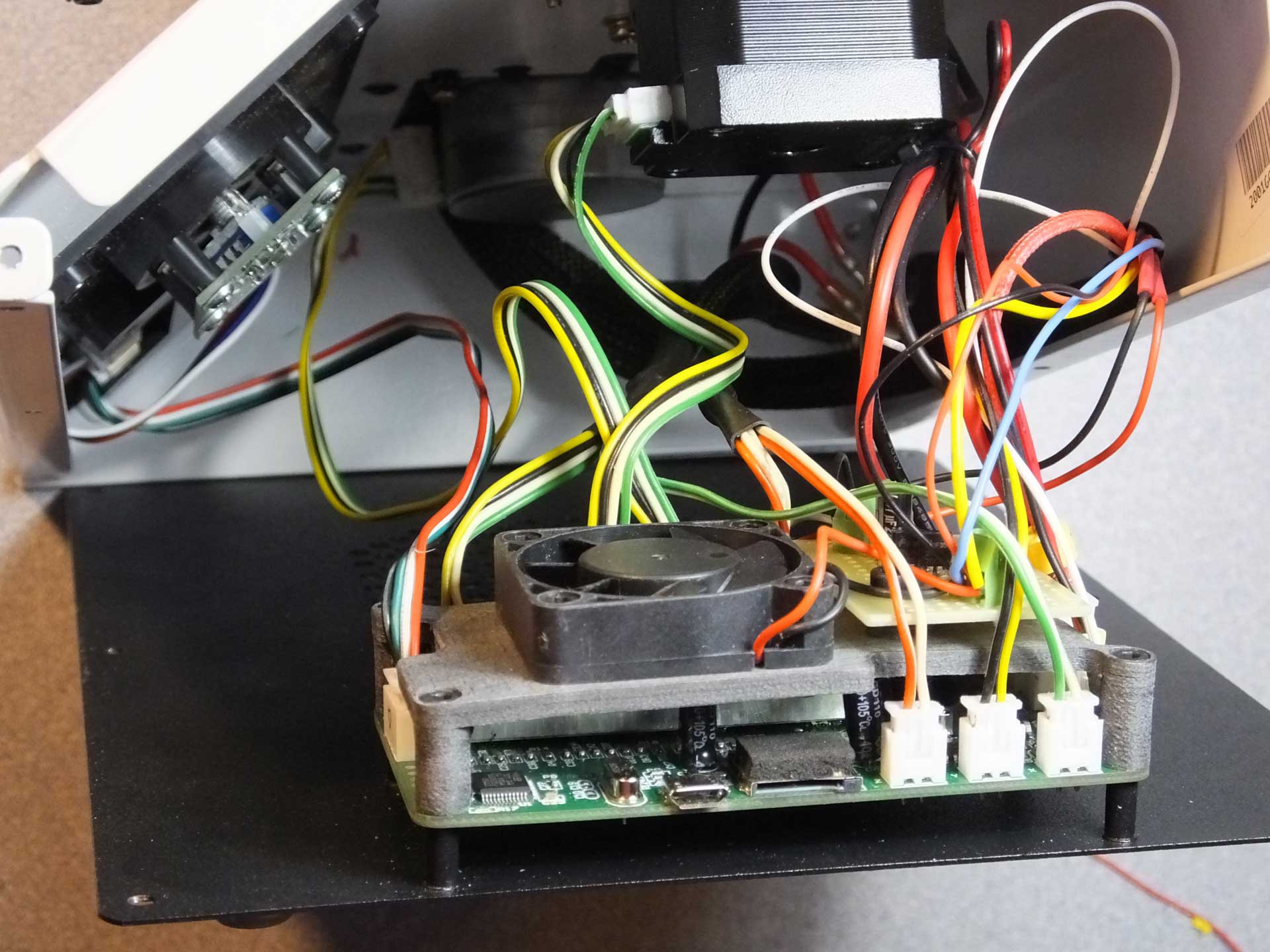
 I printed a small support bracket for the PCB I made, which was designed to fit on the top of the 40mm cooling fan bracket which I designed for the control board inside the printer. The object files for these printed parts is located on our Thingiverse page. You can get them here: http://www.thingiverse.com/thing:1867169
The cooling fan bracket can be used without the additional circuit, if all you want to do is add an internal fan to your Mini. You can see the completed cooling fan and circuit board assembly in the image below.
 I did have to tap into the 12V power and the HEATER control signal coming from the control board, but I accomplished this by soldering some short wires to the underside of the control board to pick up the signals.
 So far the board has worked flawlessly for over 100 hours of printing. I'm very pleased with the way it turned out. This mod literally cost me nothing because I had everything laying around, but as far as I can tell, the whole thing could be made for $3 or $4, depending on how much you want to spend on the fan.
Of course, you can just use the fan bracket to hold a fan that runs when the printer is on and not worry about the timing circuit. I just happen to have a thing for constantly running cooling fans, and took this design as a challenge.
Enjoy!
-
Fixing Heated Bed Heater Failure, Sensor Failure, and Y-Axis Wobble/Errors
10/29/2016 at 20:07 • 3 commentsWhile fixing issues with some wobble in my Y axis, I noticed an issue with the wiring that will cause many problems with the heated bed. I has seen on my prints that there always was a bit of slop in the layer alignment, especially in the Y axis (front to back). Nothing really that serious, but enough to be annoying. I thought it was probably due to the way the belt is attached to the bed, or something in the drive pulleys under the bed. I was going to look at it eventually, but I believe I discovered the cause of the error while I was working on a different modification I was doing.
 Check out the video below and see if you can spot the issue before I explain it and discuss my solution.
As you can see in the clip above, the way the wiring for the heated bed is placed under the bed, as the bed moves back and forth, the wiring rubs on the belt and actually deflects the belt a couple of millimeters as it makes contact. The belt deflection in this way, is certainly causing the bed to shift slightly font to back as the belt tension changes. Fixing this issue can only make things better. This is certainly going to damage the headed bed sensor or heater wires, as them move back and forth.
I was able to shift the position of the wires under the bed a little and get them to stop wobbling the bed, but after many prints the heater began to heat only intermittently, and it would stop heating if I pushed it all the way to the rear. Eventually it stopped heating, and I thought perhaps the wiring was coming loose from the movement under the bed. I used the printer without the heated bed for some time but then the bed temperature sensor started to report crazy values while printing.
I was pretty sure it was the wires under the bed getting damaged from the motion. When I investigated the problem, I ran into an obvious broken wire under the bed. The thinner wires going to the thermistor were not visibly broken, but under the insulation the wires were failing and I could make the temperature on the screen change to crazy numbers by shifting the thin wires around. It looks like I would have to replace the wiring on the heated bed. But how would I correct the issue?
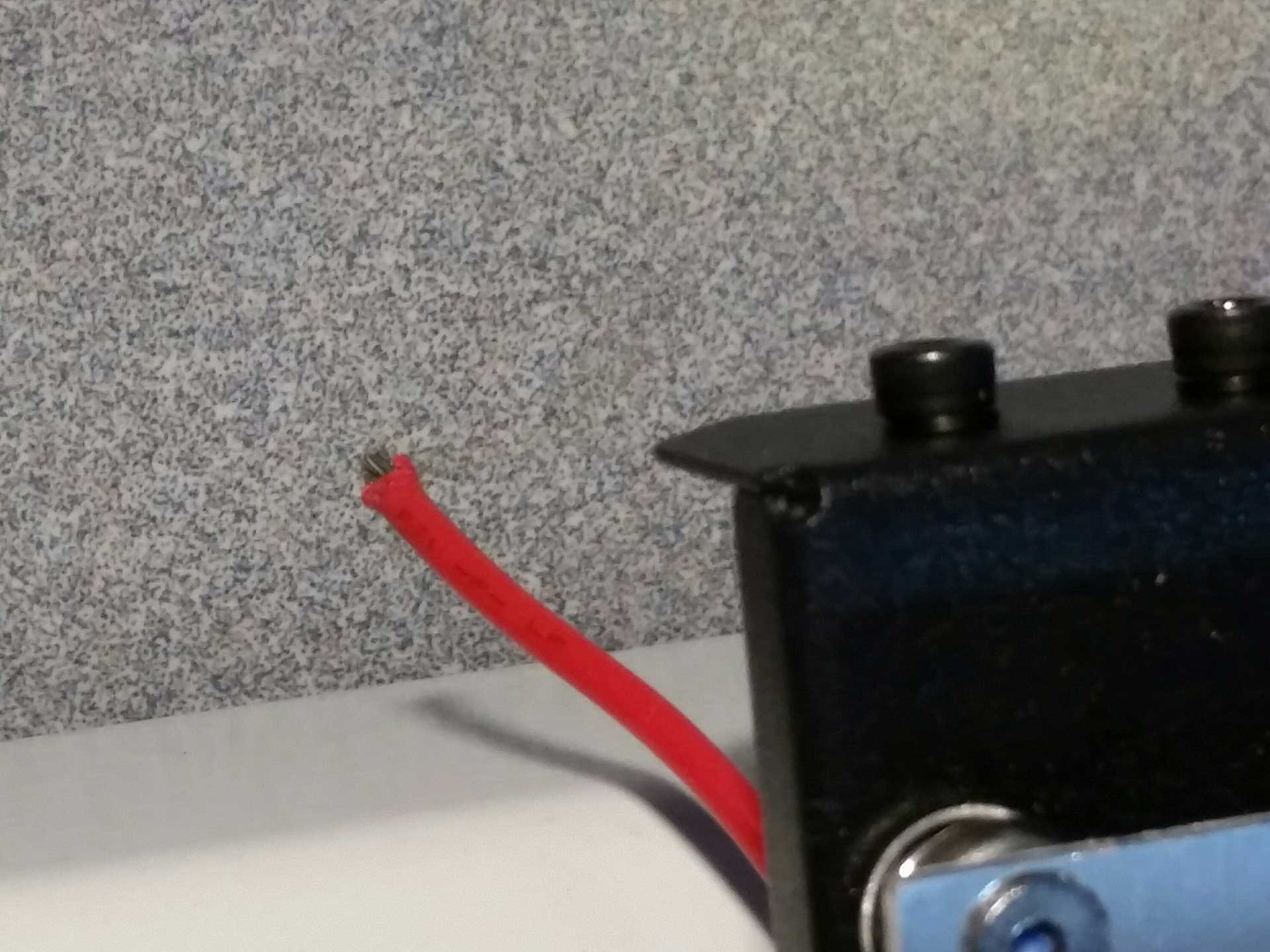
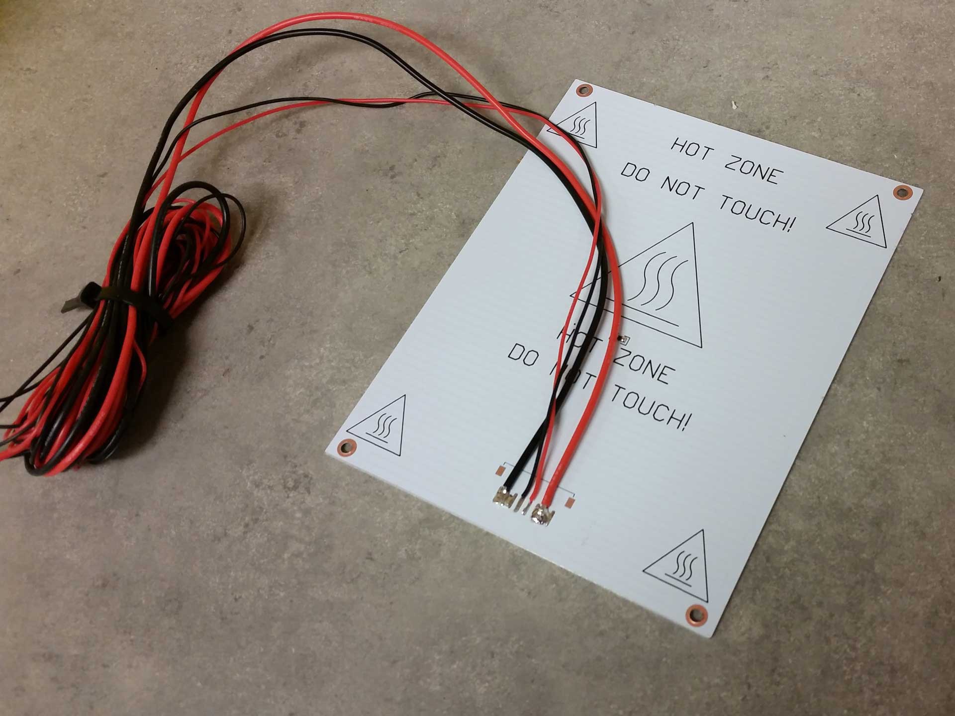
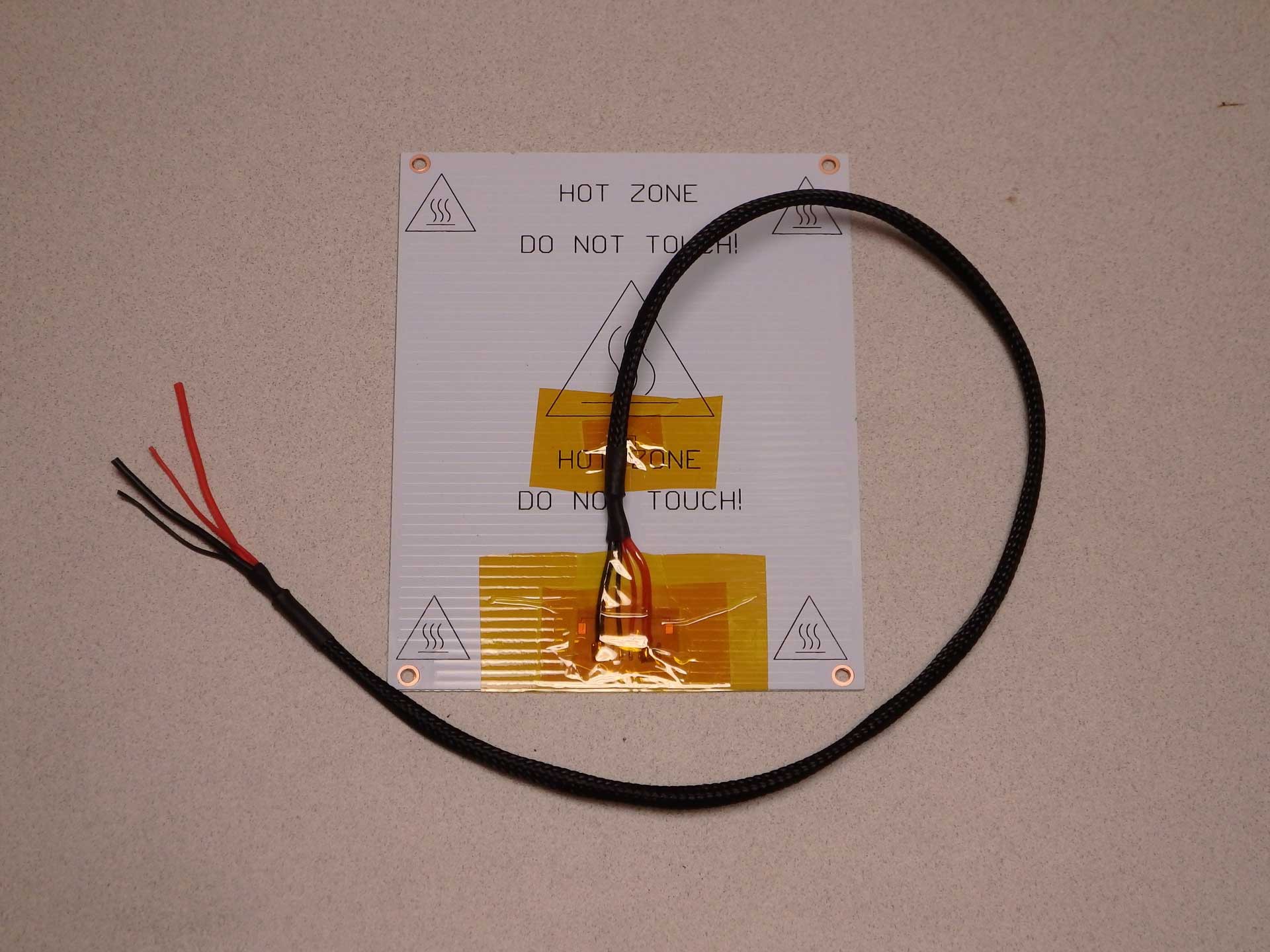
 My solution was to replace the heated bed wiring with better quality wiring and route it so that there would be no stress on the wires and no interference with any of the moving parts. For the wiring, I chose to use silicone jacketed wire which I had on hand for my rocket and quadrotor experiments, which I purchased in bulk from Hobbyking. I probably only used a dollar or so of the wire if I were to buy it separately.
 Soldering the wires to the heated bed proved to be a challenge as the aluminum would keep the iron from heating the solder. I ended up warming the whole bed up with a heat gun and then soldering the wires. Pre-heating the aluminum was enough to let the soldering iron work on the joints.
While I was in there, I also reflowed the thermistor with some lead solder I had on hand. No-lead solder is notorious for being brittle, and other people have reported that their thermistors fail from heat expansion/contraction cycles of the board, or from flexing the board during print removal. By flowing the joints with more flexible lead solder, I hope to prevent any of these issues on my heated bed.
I applied liberal amounts of Kapton Tape to make sure nothing would ever short out, or pull loose. I also dressed up the wires with more of the cable sleeve I salvaged from a discarded PC a while back. It dresses up the wiring, and probably helps with strain relief of the moving wires.
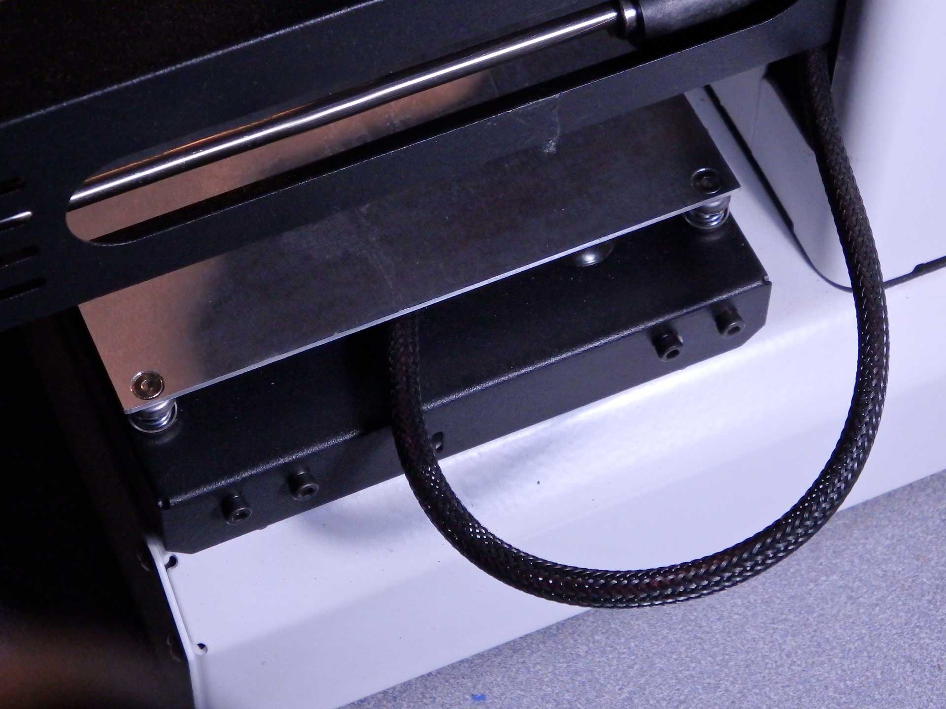
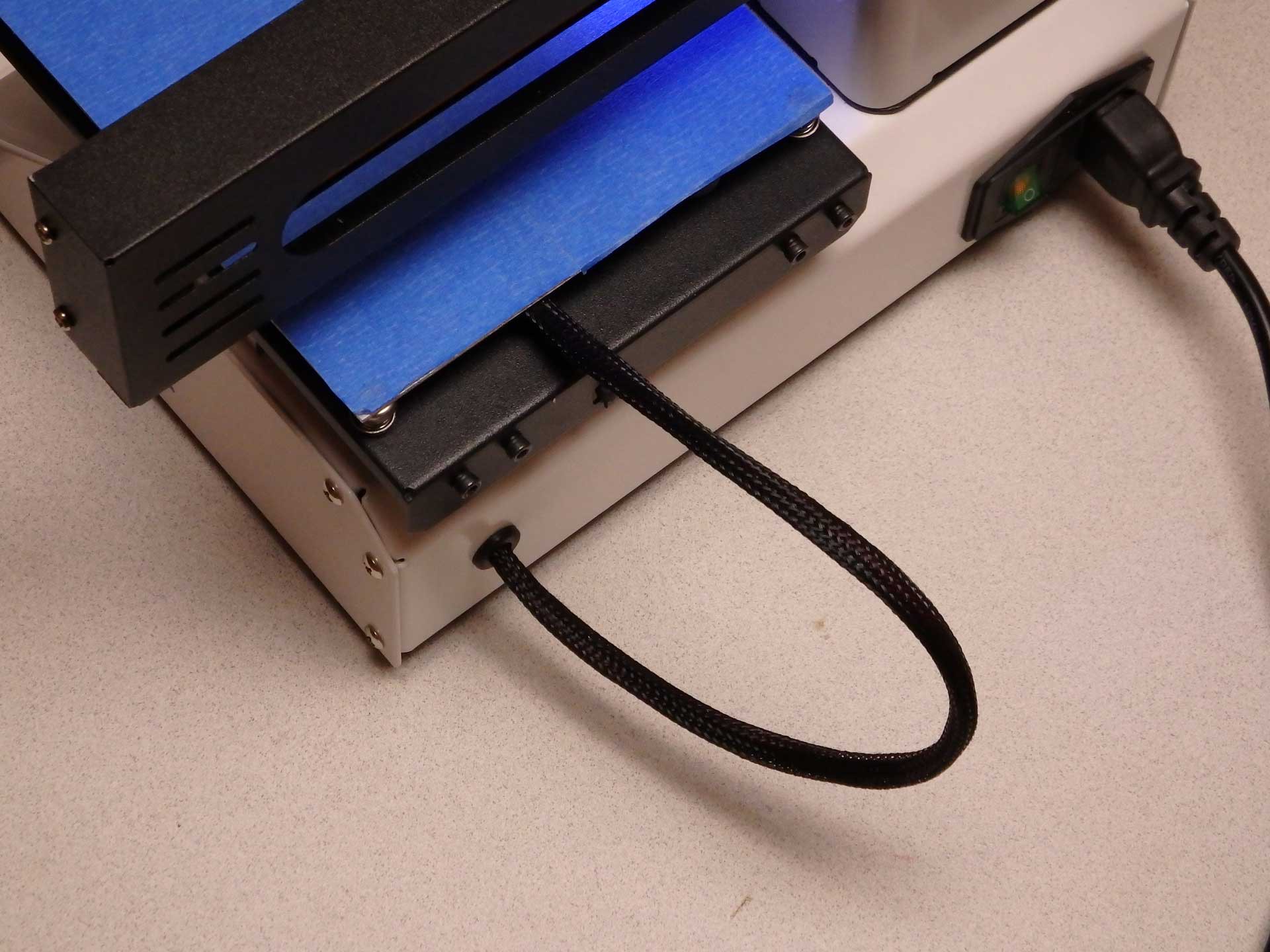
 To solve the original Y-axis belt rubbing problem, I re-routed the heated bed wiring through the slot in the Z-axis tower. The gantry never lowered enough to interfere with the wiring, and the new cable routing solved all the issues with the belt. The wire actually moves very little ones it is not confined under the bed. This wire configuration should be standard on the Mini.
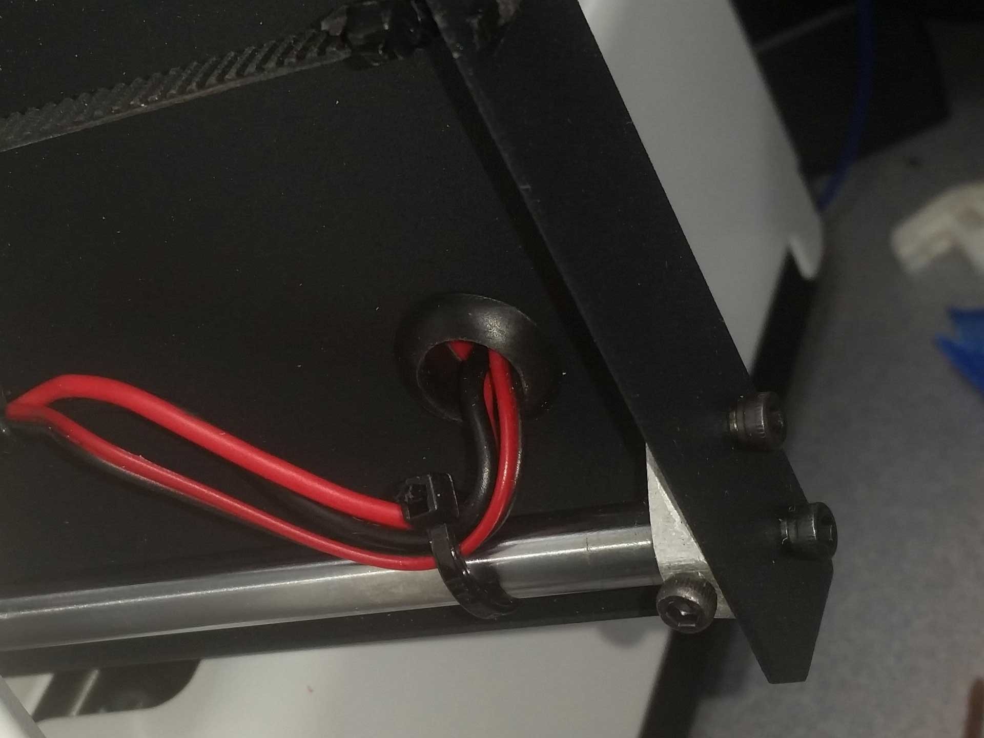
 Ultimately, I decided I didn't like the length of the heated bed wires, so I decided to make a hole in the back of the printer and transplant the rubber grommet from the bed to the rear of the printed, and feed the wires directly out the back of the printer below the bed. I like this approach because I was able to make the wiring a lot shorter. This is even better and should really be the way the printers are built from the factory (even better than my last suggestion).
I think I would like to design a printed cable attachment point to one of the screws that attaches the rod ends to the bed tray. Right now the kapton taps is really the only thing that secures the wiring to the bottom of the bed.
Watch this space for an update when I have the printed part designed and test fit.
-
Zero Offset E3Dv6 Hot End and Part Cooling Fan Files are Now Available
10/26/2016 at 02:06 • 2 comments The files and installation instructions for this setup are now available on our Thingiverse Page. To download these files, please go to:
http://www.thingiverse.com/thing:1848402
Thanks for your feedback and comments! We appreciate the encouraging words!
Monoprice Select Mini Maximum 3D Printer Mods
Low/zero cost upgrades for the Monoprice Select Mini 3D Printer.
 U.S. Water Rockets