 nerd.king
So I waited a week to get the new motor only to find out that the old one had toasted some of the FETs and some really odd behavior was occurring. I decided to build a new shield up from scratch but I had to order some additional FETs.
So today I got the current board to run through all commutation stages with the LED test fixture.
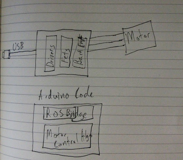
Here is the horribly simple architecture diagram. The pic makes the assumption that the Arduino io will drive the FET drivers. Hopefully this week I can get the new motor hooked up and running.
Discussions
Become a Hackaday.io Member
Create an account to leave a comment. Already have an account? Log In.
Are you sure? yes | no