 origamimavin
-
1Step 1
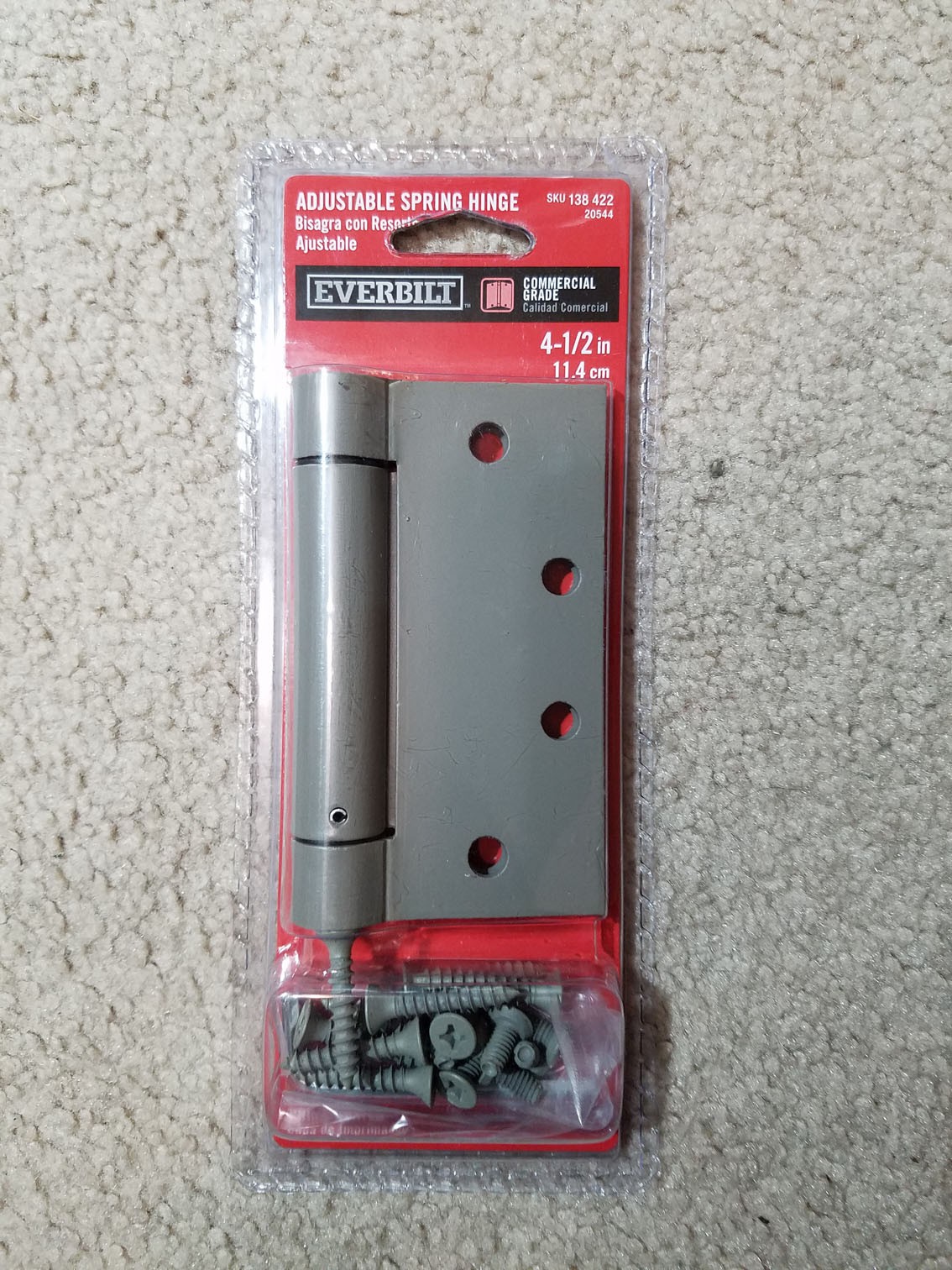
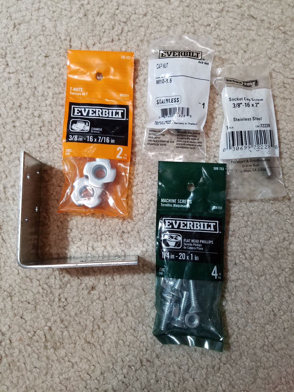
These are the parts I bought for the project:
- Everbilt 4.5" adjustable spring hinge - 1x
- Metal angle bracket (sturdy) - 1x
- 3/8" - 16 x 2" SS Socket Cap Screw - 1pk
- 3/8" - 16 x 7/16" T-Nuts - 2pk
- 1/4" - 20 x 1" Flat Head machine screws with nuts - 4pk
- M10 Cap Nut (acorn nut) (they didn't have 3/8" cap nuts, but this will thread onto the 3/8" screw)
There's no sales tax in my state, and the total cost of these items was just under $27 from my local Home Depot. The spring hinge was the bulk of the cost at around $17.
In addition to these bought parts, I used some 1/2" and 1" thick acrylic plastic (not pictured in this step) I had around the house. Other plastics or dense wood could probably be used to replicate this.
![]()
![]()
-
2Step 2
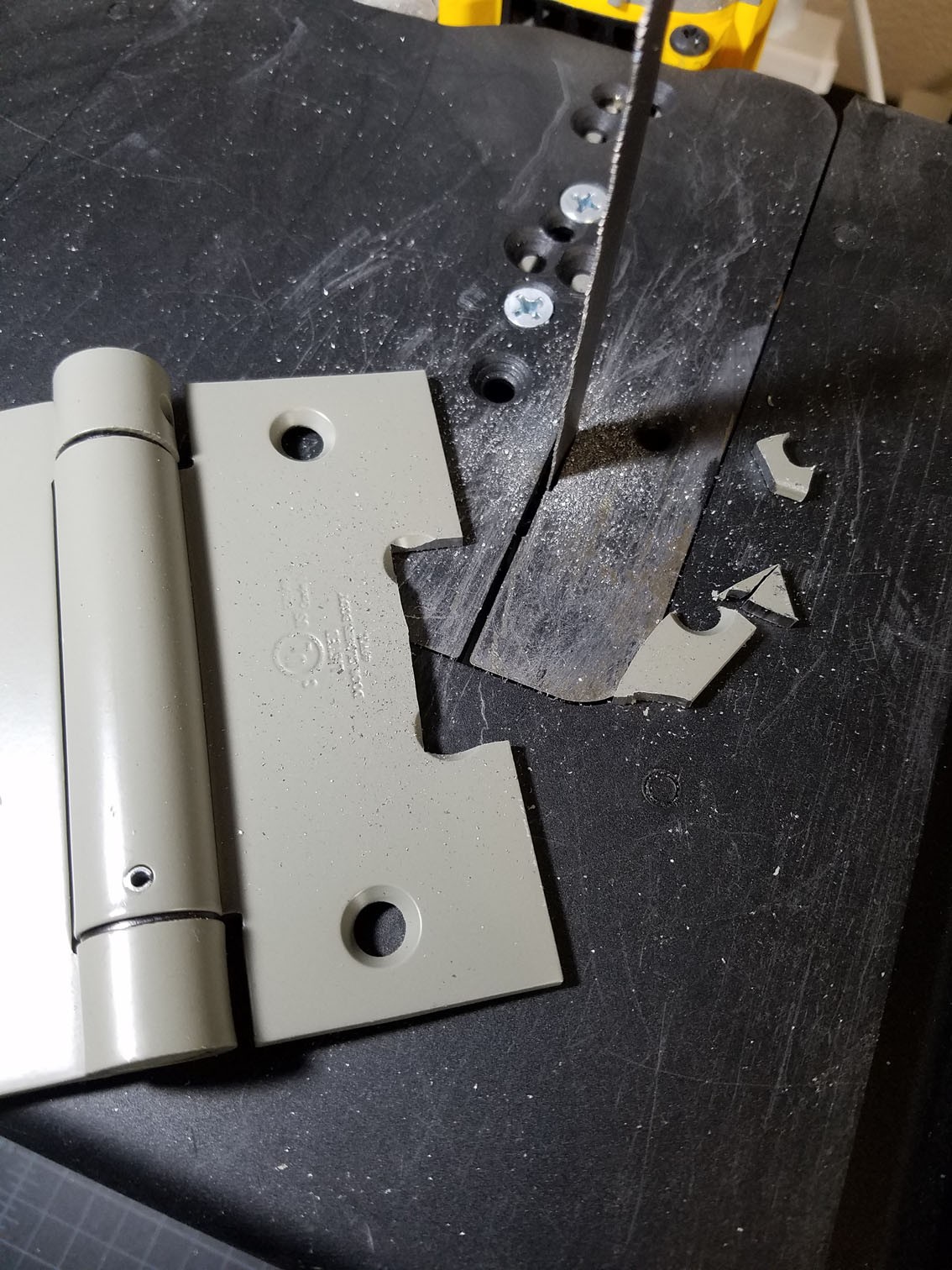
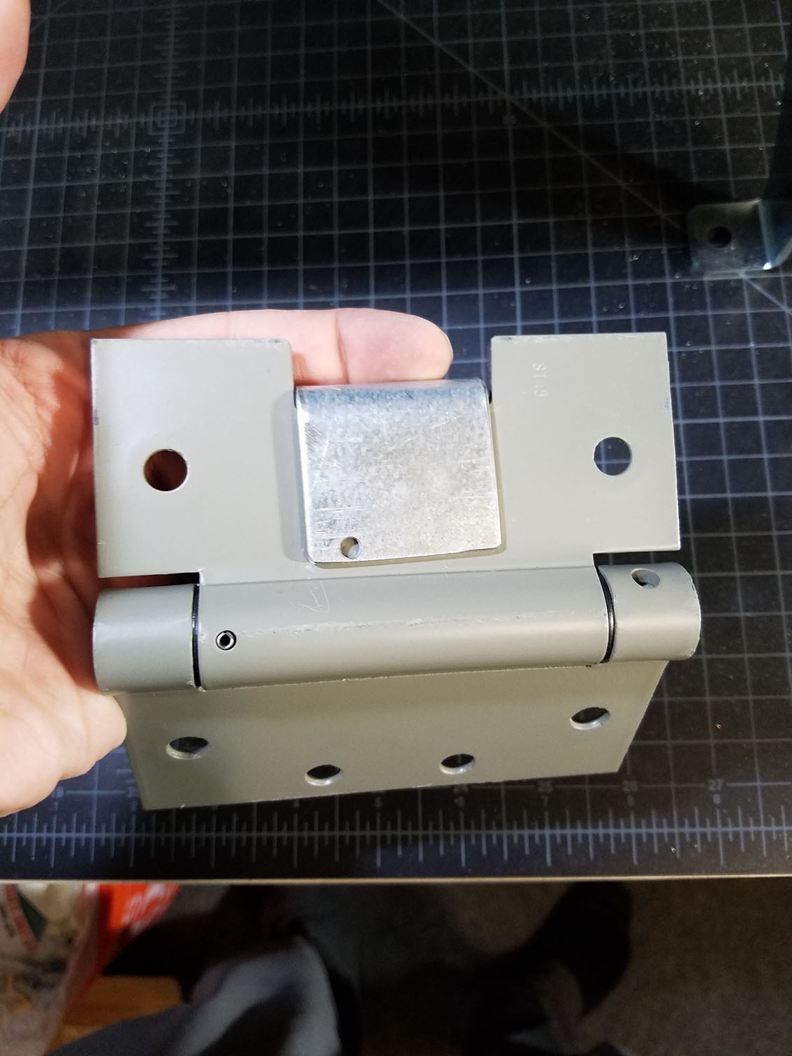
Next I needed to make room for the angle bracket to sit closer to the hinge pivot, but also use the hinge itself to hold the angle bracket in place. I cut this out on the bandsaw, using the existing screw holes as a guide for centering and depth of cut.
![]()
![]()
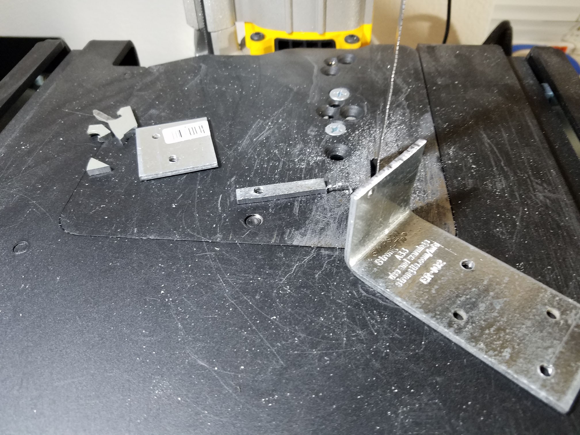
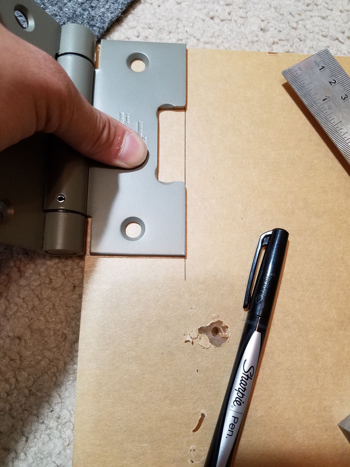
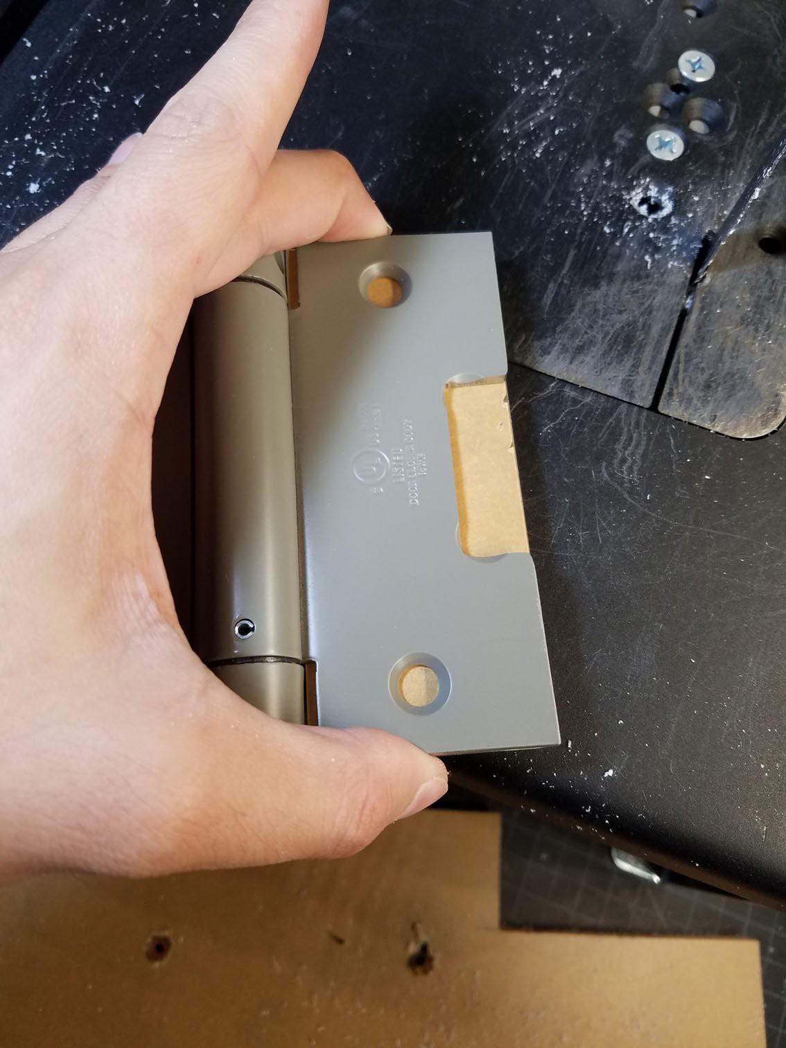
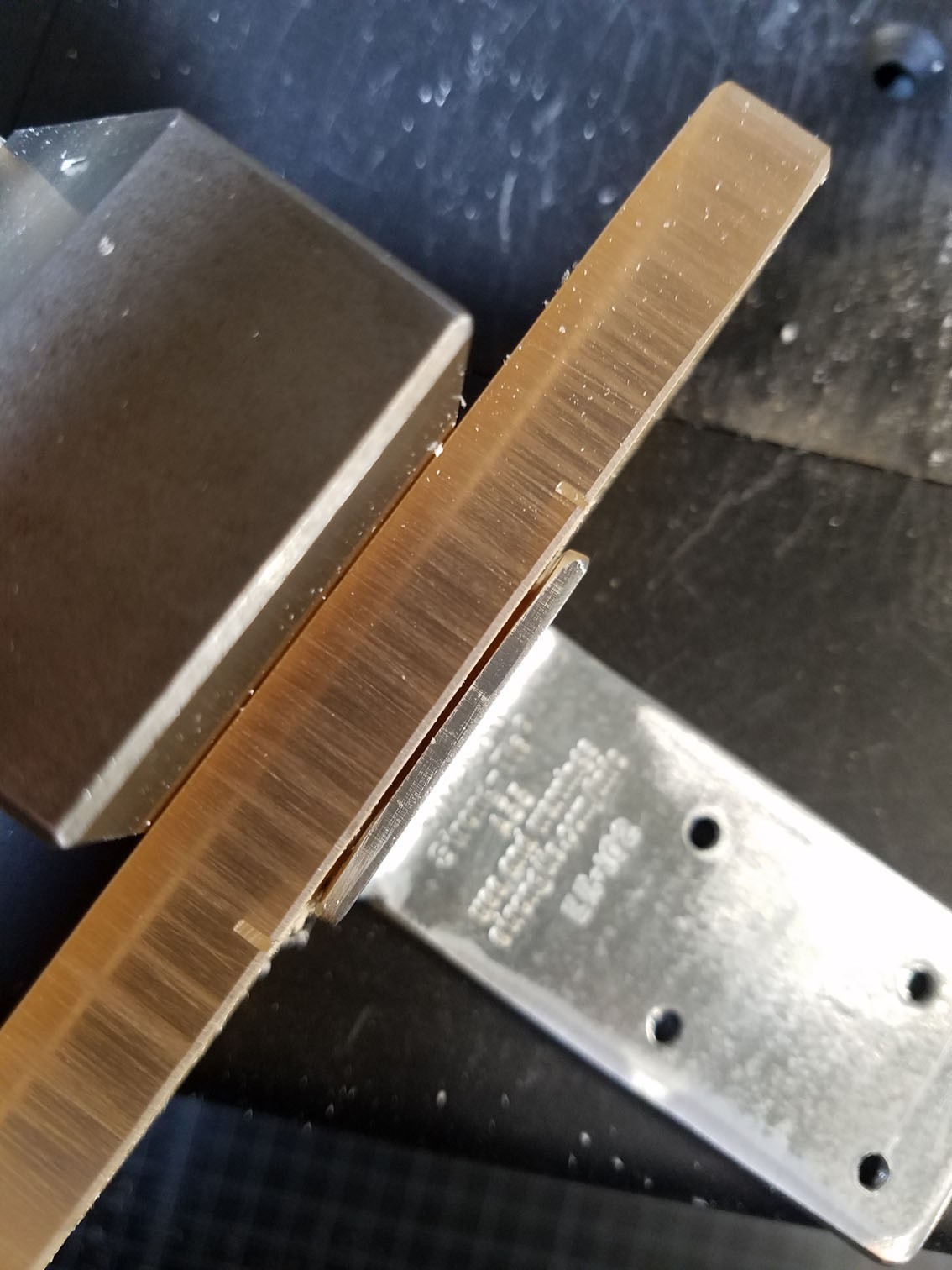
Then I cut the angle bracket to fit, so it wasn't sticking out past the flat part into the pivot
![]()
![]()
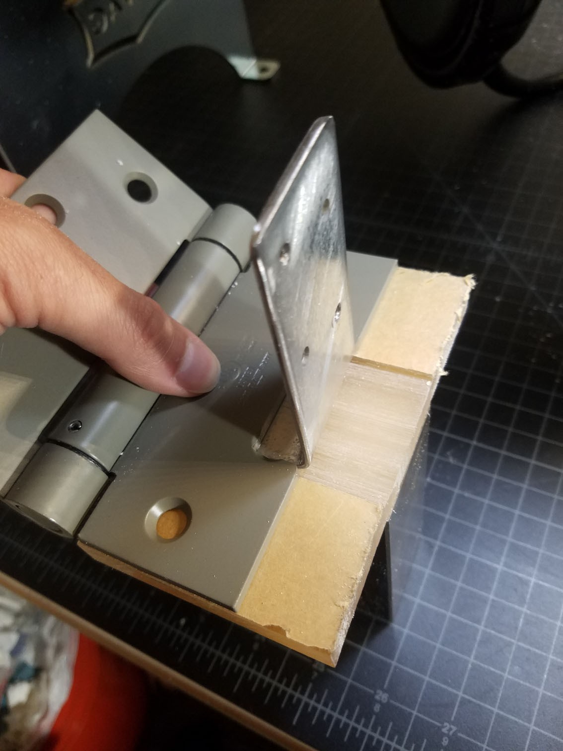
This is a good view to explain this element of the design. The horizontal part of the angle bracket, as shown in the image above, will take most of the spring force from the hinge and hold everything in place as it's being uses. As a result, the vertical part of the angle bracket will be structurally sound and hold a consistent angle.
-
3Step 3
Then I cut out some of the 1/2" acrylic to make the base, which will also hold everything together. I made a mistake in this step and cut the plastic too small, but documented it better on the small piece, so all of the images in this step show process, not the final design:
![]()
![]()
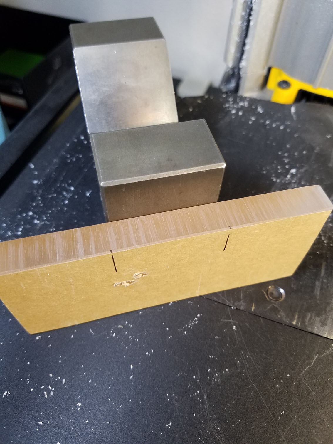
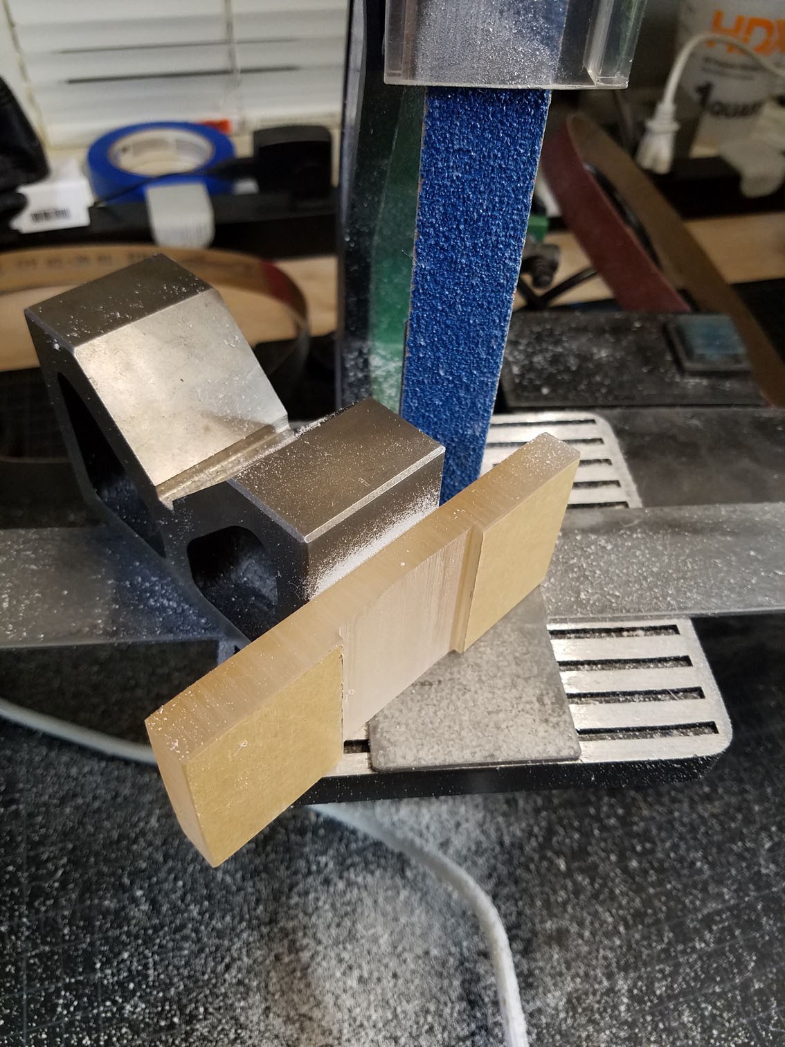
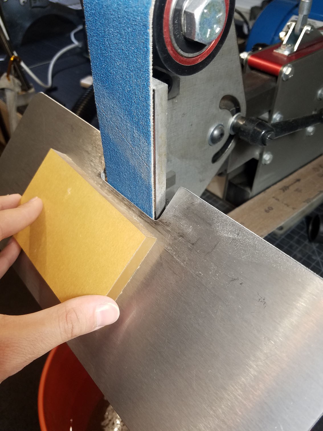
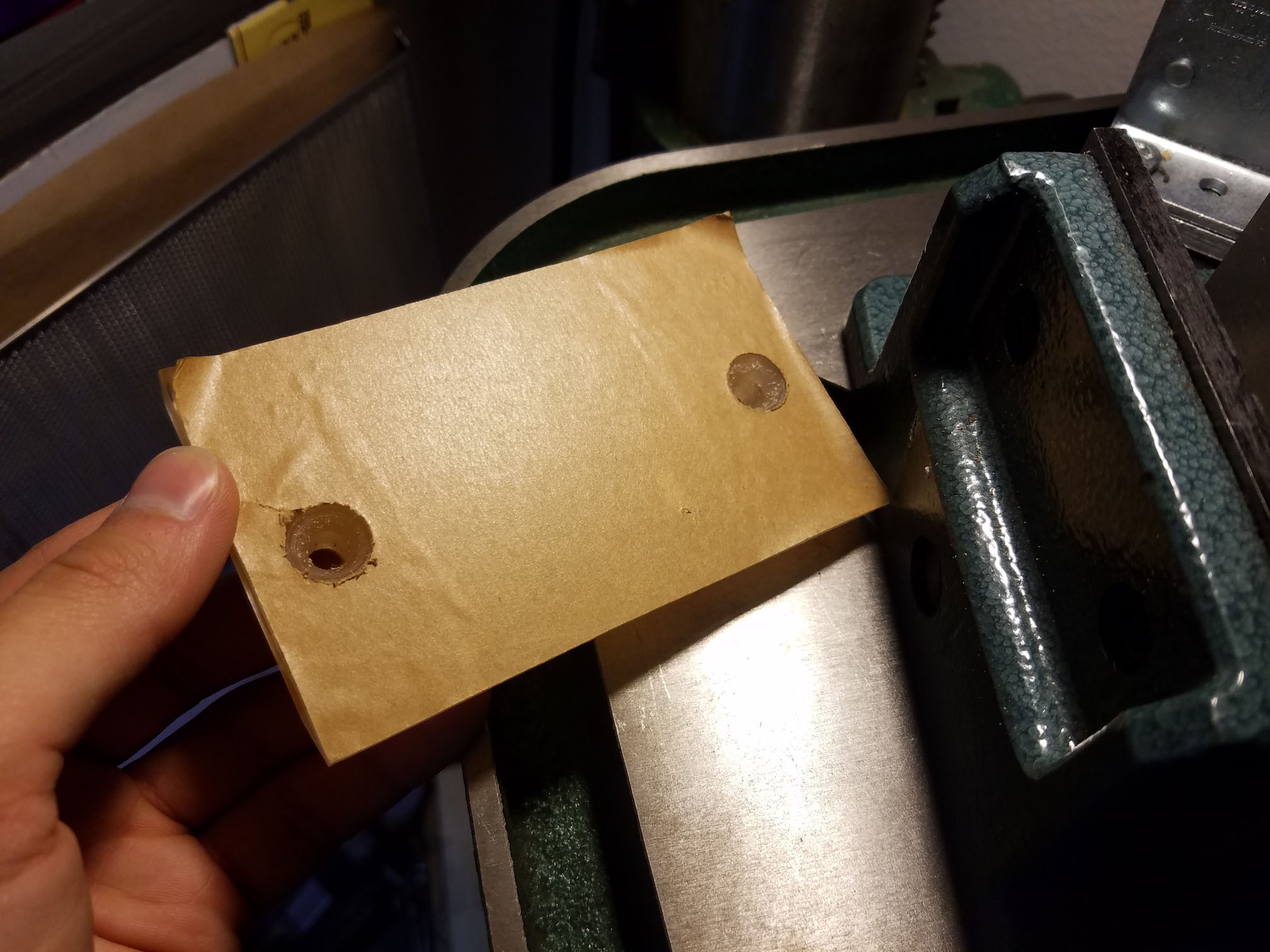
Once cut, I double stick taped it to a 90° V-block to hold it upright.
![]()
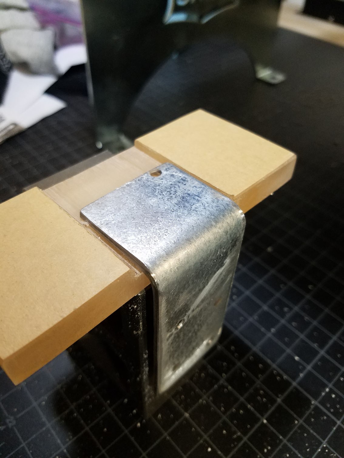
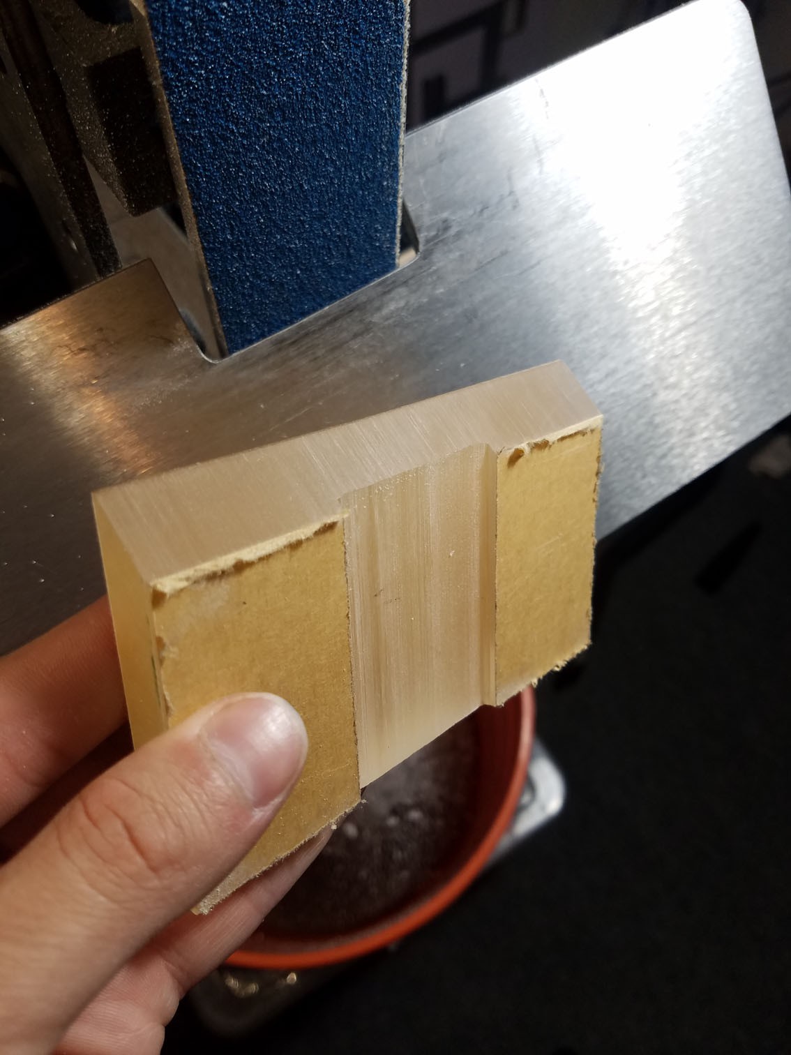
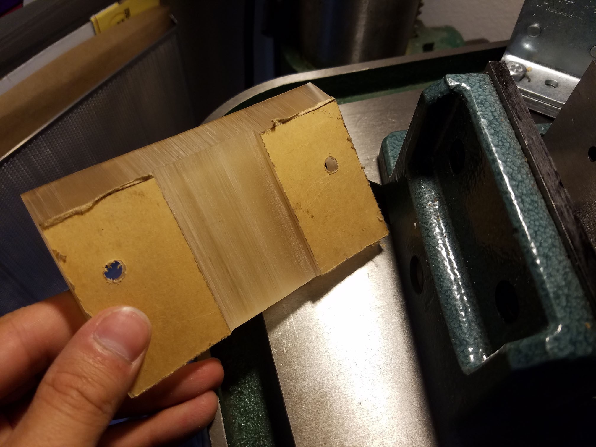
Using the bandsaw, I made two notches into the plastic to make a reference for the width and depth of the material I needed to remove based on the dimensions of the angle bracket.
![]()
By using a 1x30 belt grinder, I was able to remove the material needed. I found that removing too little material was better than removing too much, as a tighter fit works best.
![]()
![]()
![]()
![]()
-
4Step 4
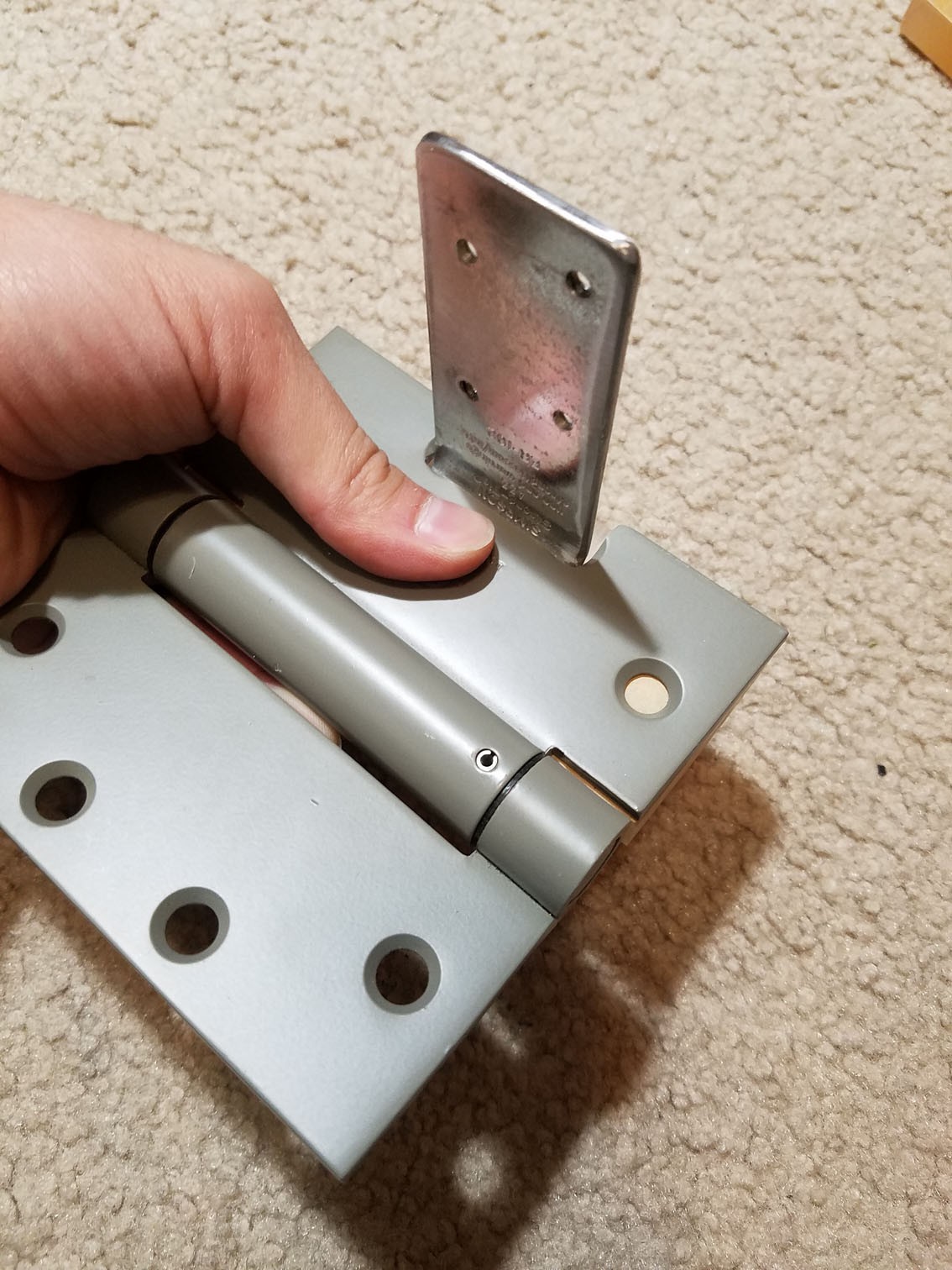
Here you can see the final, wider piece of plastic I used. Once I completed the previous step, I realized that the base wasn't stable enough and would rock towards the hinge, so it needed to be supported better. Here you can see the wider base:
![]()
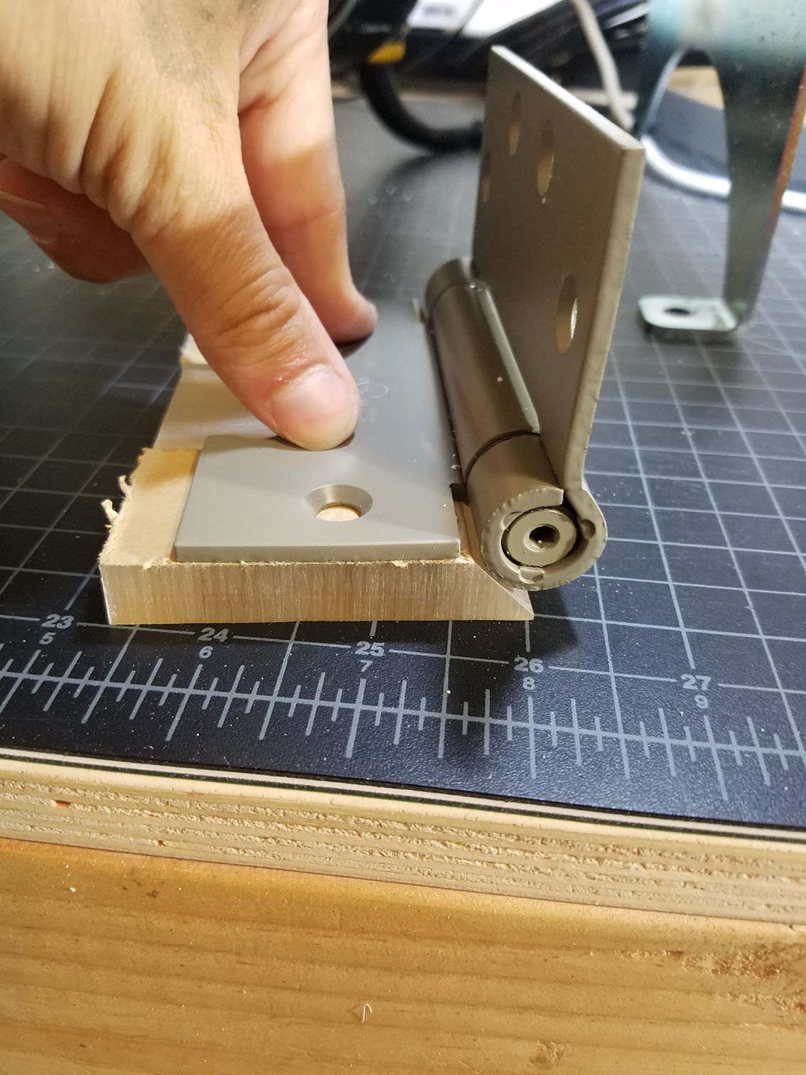
In order for it to support the pivot area, I needed to remove some interference material. I used my 2x72 grinder to remove a 45° angle from the leading edge to create this clearance.
![]()
![]()
Now comes assembling the base. I lined everything up and lined up where I needed to drill the screw holes. Using the drill press, I drilled holes for the 1/4"-20 screws and countersunk the bottom side to make clearance for the screw heads. I added a couple washers I had lying around the house so they sit better.![]()
![]()
![]()
![]()
![]()
![]()
-
5Step 5
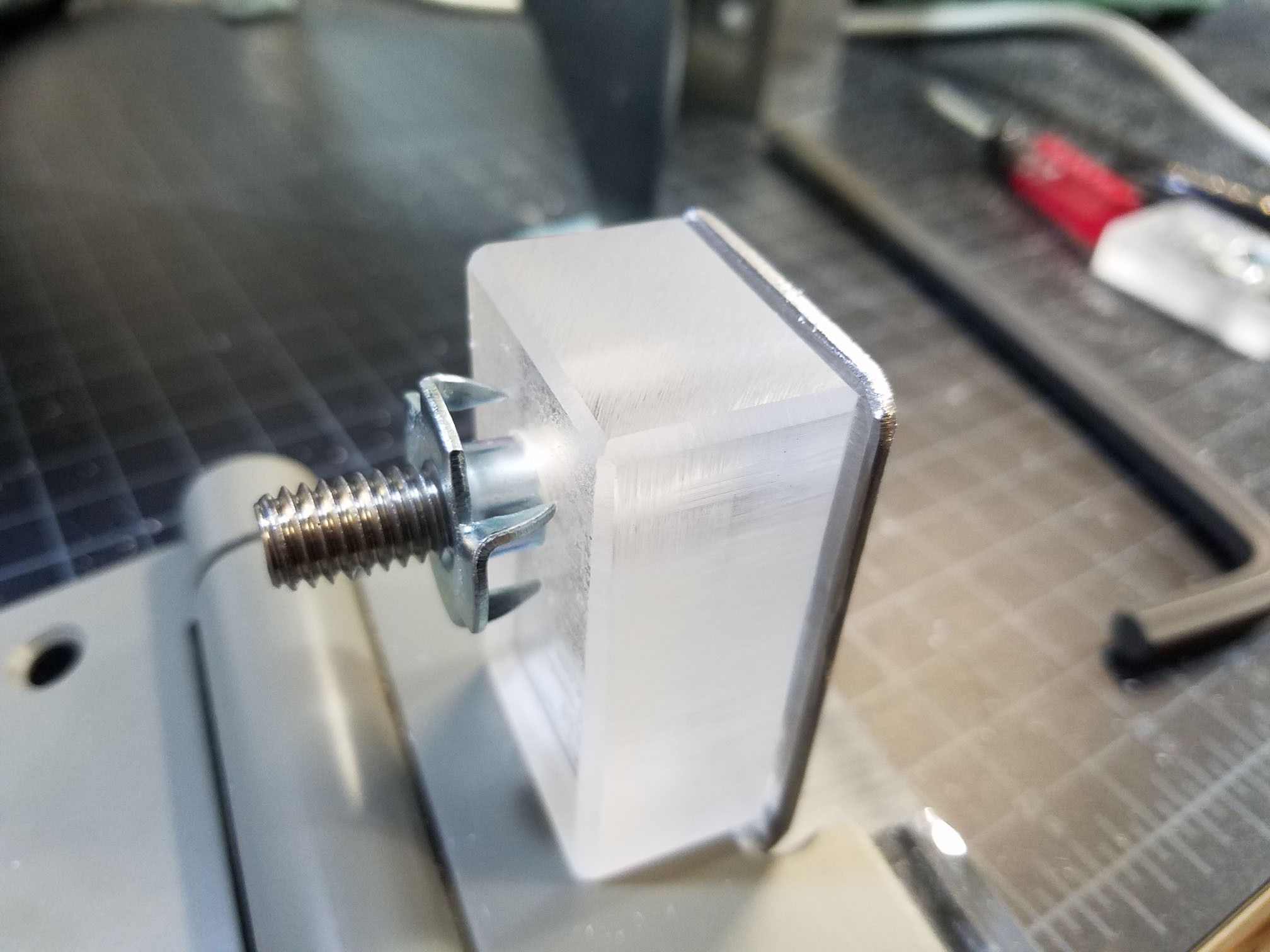
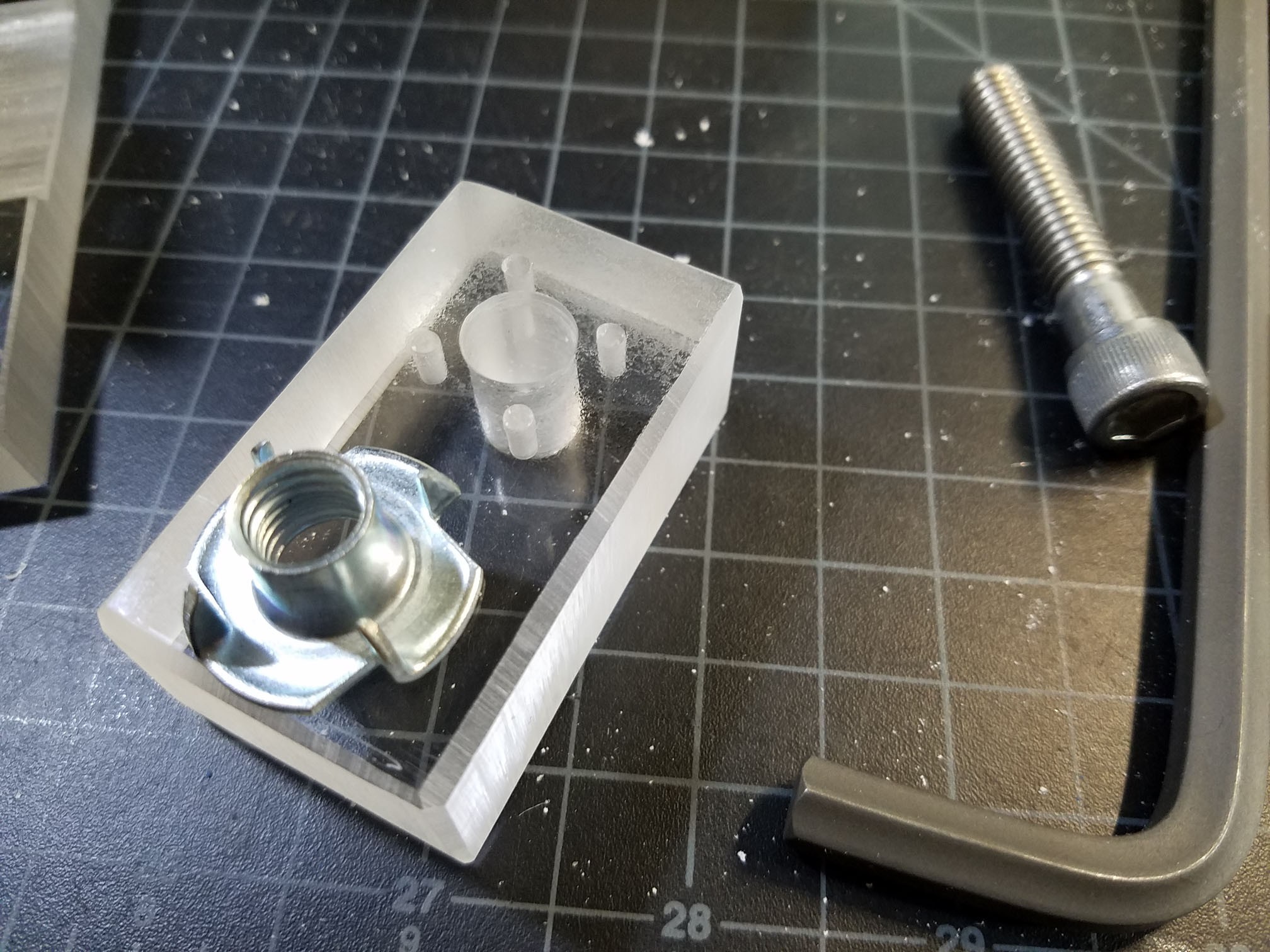
Next up was adding the mount for the 3/8" screw, which will adjust the angle. My first attempt at this was with some more of the 1/2" plastic, but I found that the unthreaded part of the screw hit the T-nut too soon, which limited the angle, so I switched it with some 1" thick material. I documented it better on these steps, so the images are accurate.
I started by picking a good height for the screw and drilled a hole in the angle bracket (not pictured)
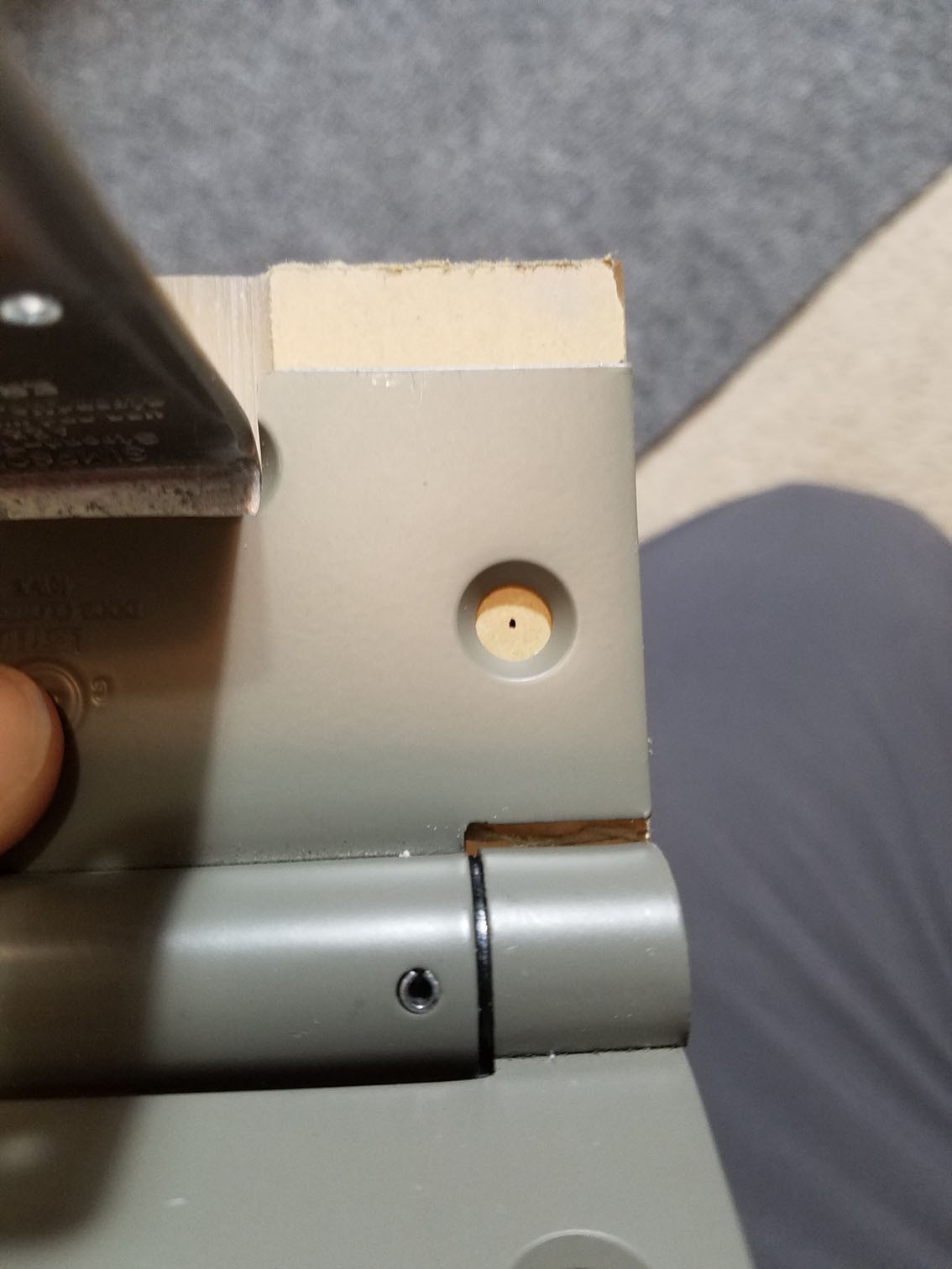
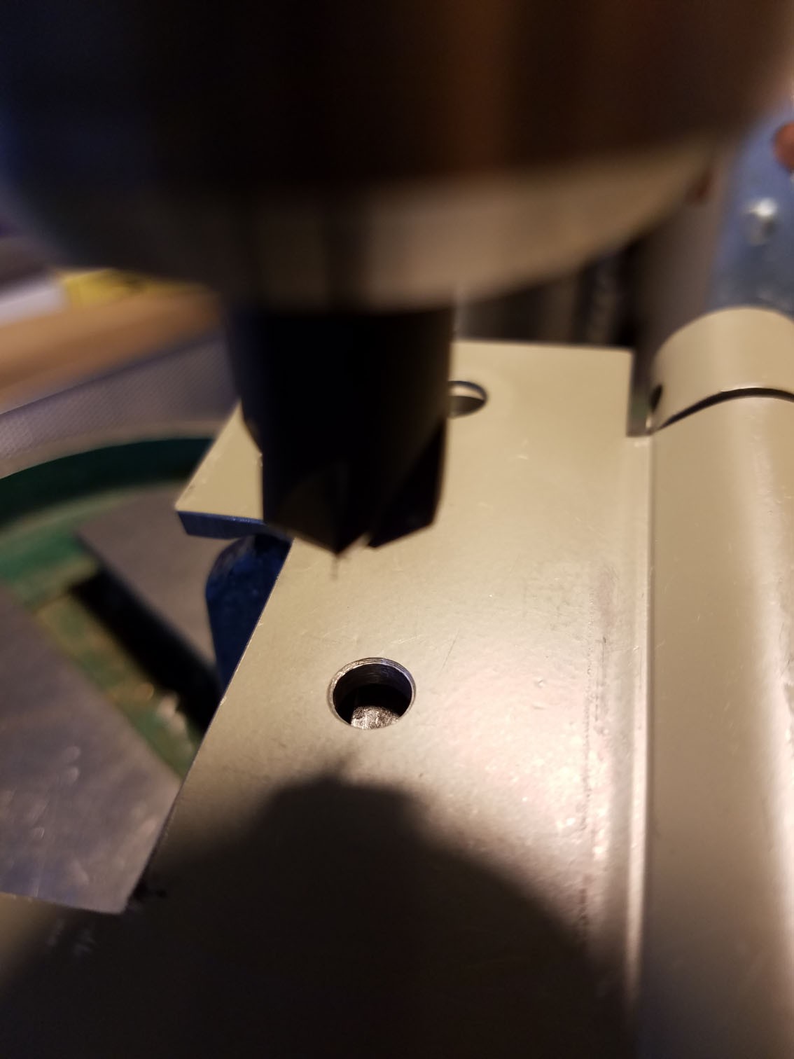
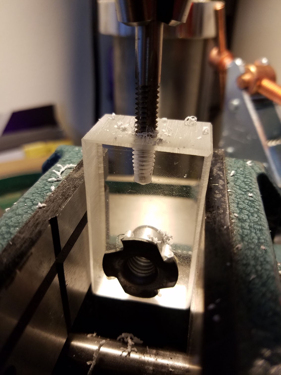
Then I lined up the piece of plastic to find the center and drilled that hold out for clearance (also not pictured, I was too busy switching the drill press speeds for the material changes). This is the result, with the T-nut held in place by the screw.
![]()
![]()
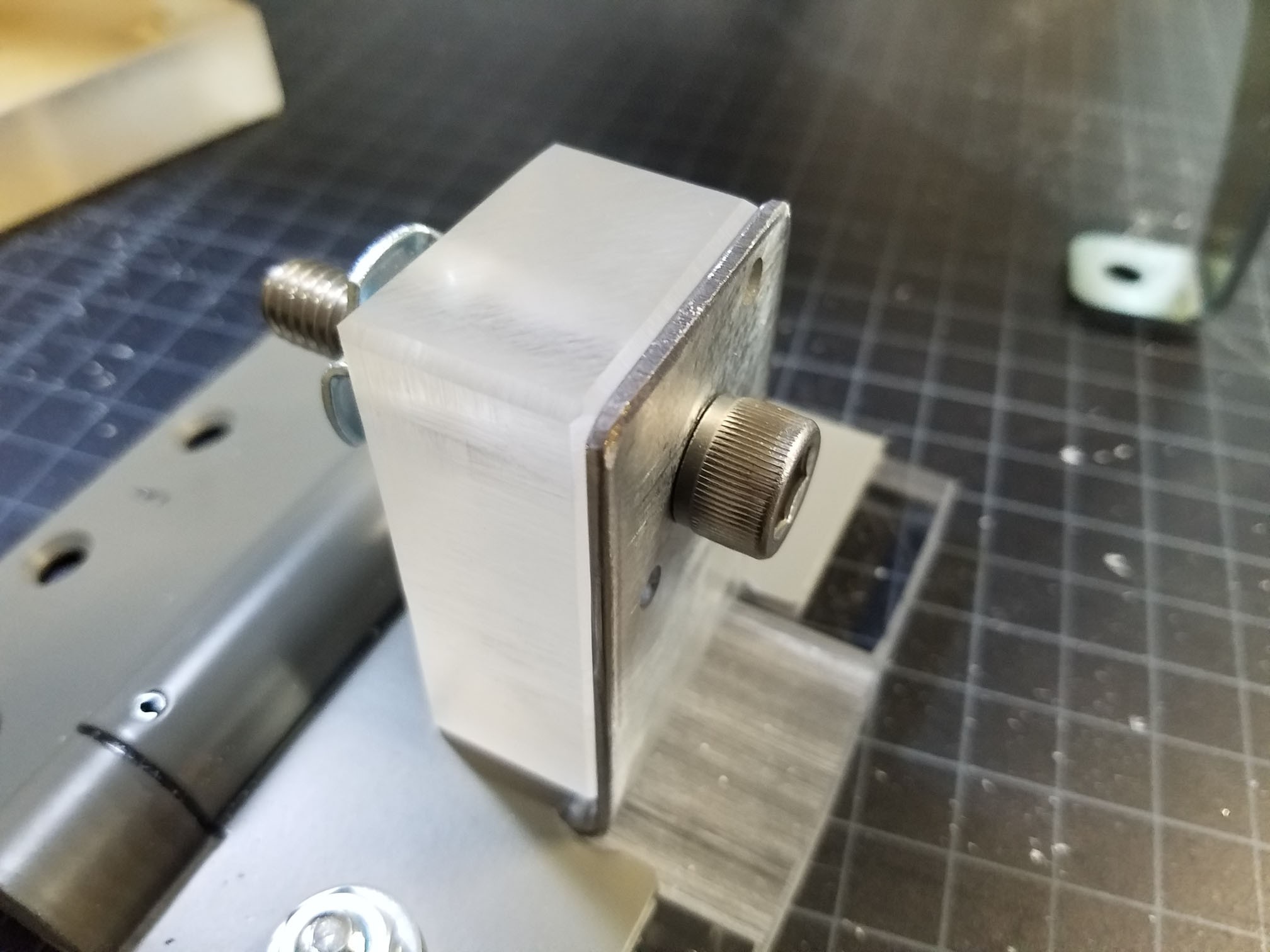
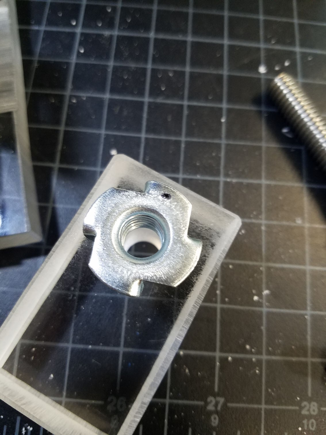
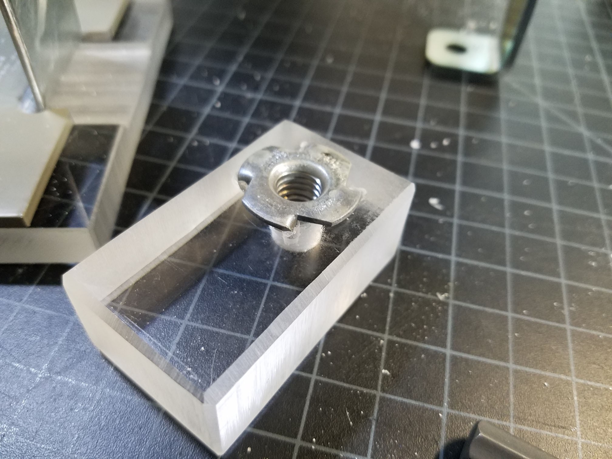
Mark one part of the T-nut as the top (since the prongs are bent slightly off) and tighten the screw to make little indentations in the plastic.
![]()
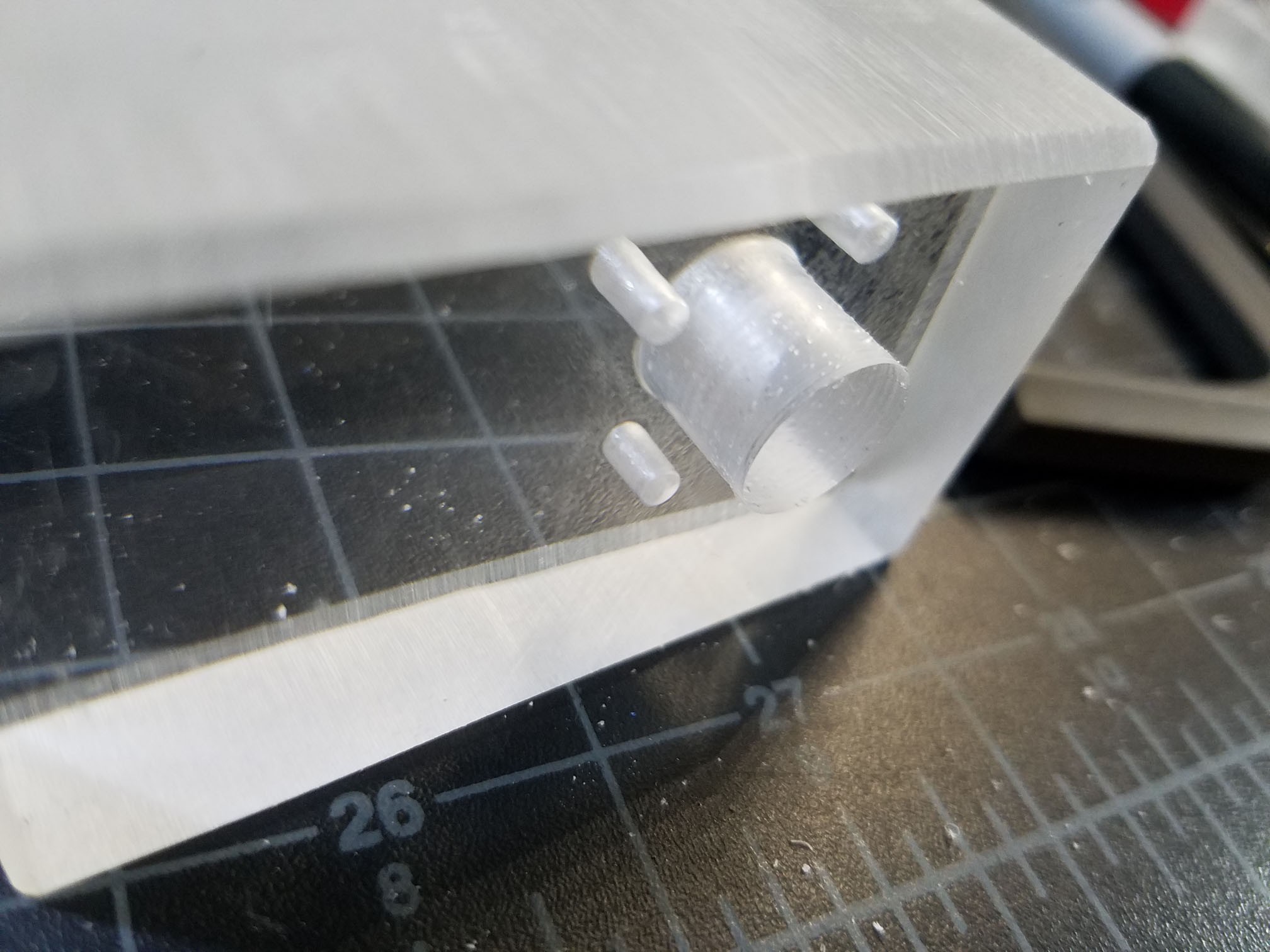
That will give you a guide for where to drill the clearance holes. Pick a drill side that will accommodate the T-nut about half way down the prongs, but that's it. The depth should be able to accommodate the whole prong depth, though.
![]()
![]()
Thread the T-nut onto the end of the screw so you can hold it, and heat up the prongs of the T-nut with a torch. Remember that bit about yada yada safety? Be smart with the torch. Once it's hot (doesn't need to be red hot), line up whichever side you marked for the top and press it into place. It may take a couple times of heating up the metal. Let it cool off and revel in having found a project where you can use a torch.
![]()
-
6Step 6
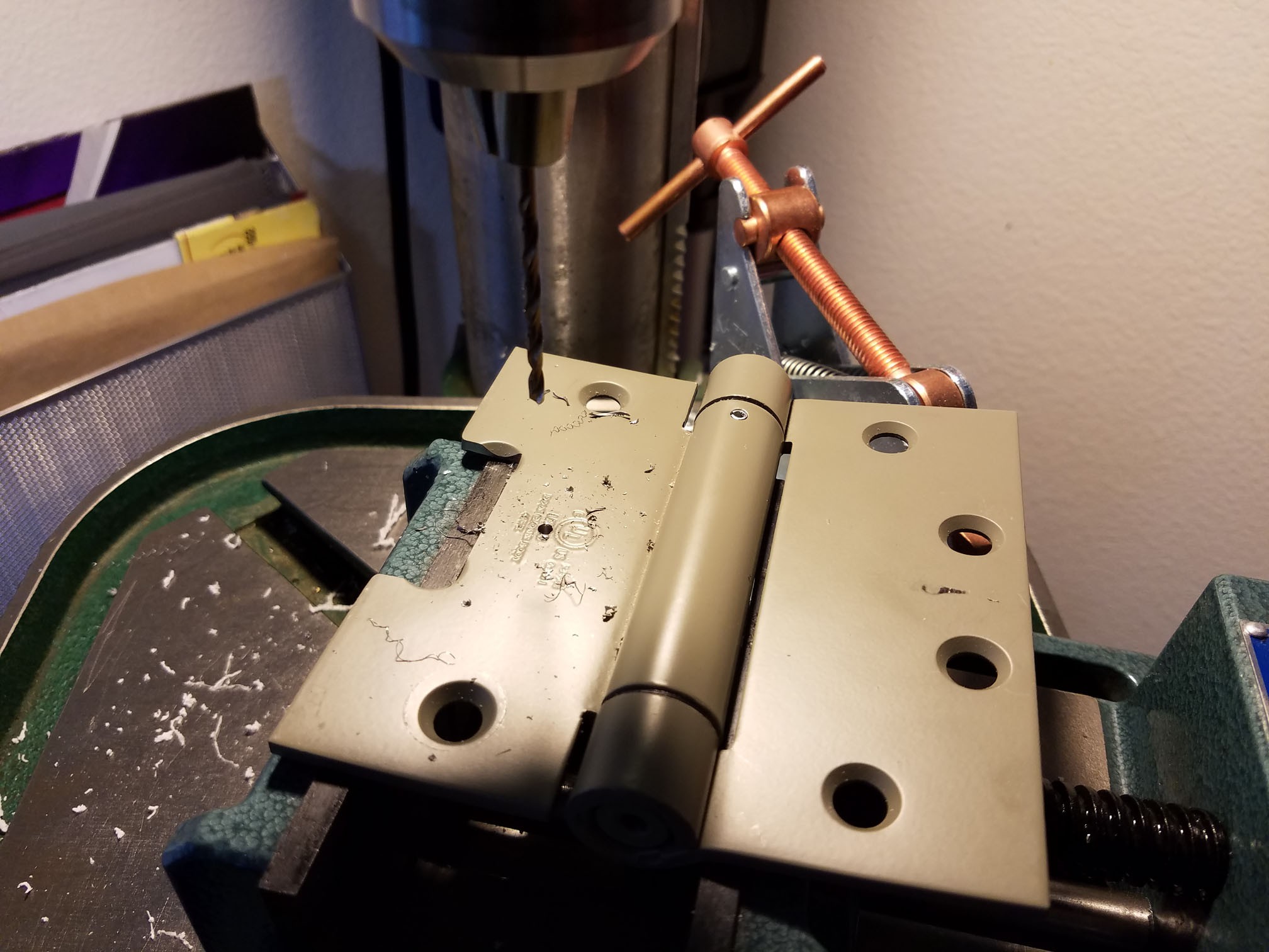
Next, measure about half way into the thickness of the acrylic and transfer that point to the hinge. This isn't pictured either, since I was busy fumbling with lining everything up, having picked the least effective way to accomplish this task and again changing over drill press speeds. You can get the idea of what needs to be done based on the following pictures. This will be for another 1/4"-20 screw.
![]()
Countersinking holes all pretty makes me feel good, so I took the opportunity to do just that.
![]()
Line up the angle bracket and drill that hole as well. Close the hinge as far as it will go to make sure the angle bracket is straight, then clamp down the baseplate screws from the earlier step and mark where to make the hole.
![]()
Next, like up the piece of 1" thick acrylic and make a mark there as well. When drilling this hole, make it a bit deeper than the depth of the screw, and tap the hole. Since this was the first hole I was tapping since I got my drill press, I attempted a method I either read somewhere or thought of which worked out pretty well. I undid the belts up top so there was no resistance on the chuck and chucked up the tap into the drillpress. I turned the chuck by hand while lowing it, tapping the hole nice and straight. Worked like a charm!
![]()
I forget the order of it, but I also drilled another hole in the base to match all this, and gave it a countersink to accommodate for the screw head (not pictured).
-
7Step 7
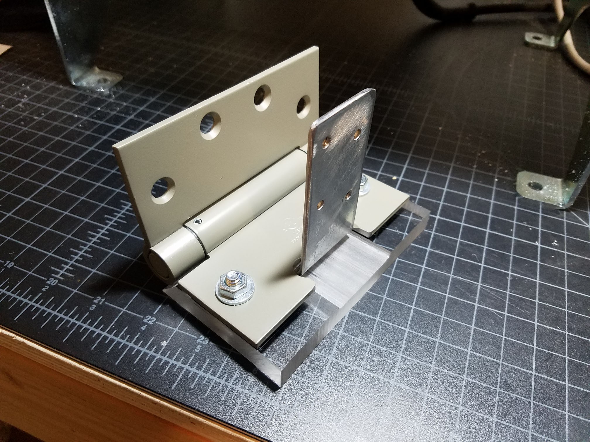
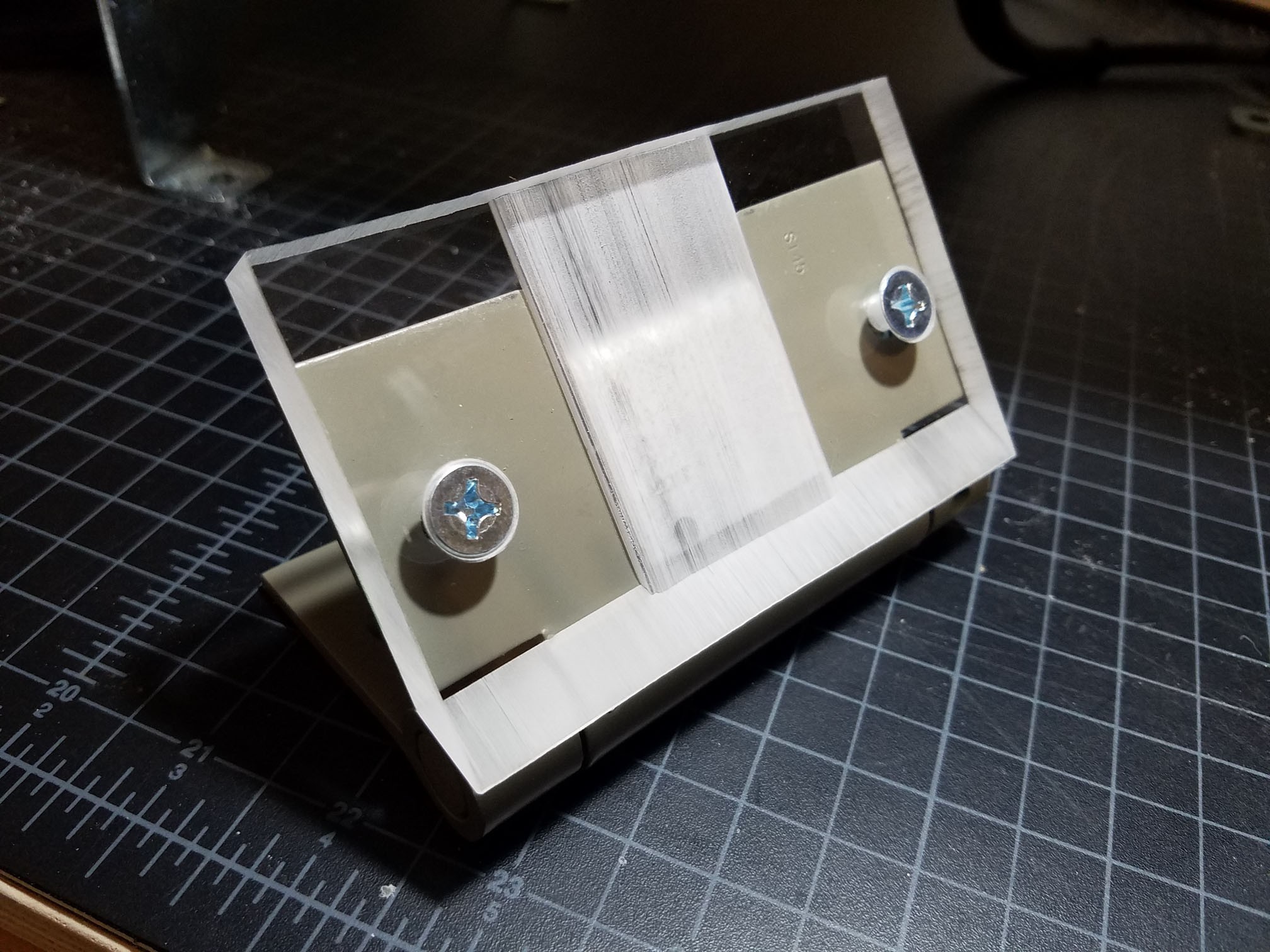
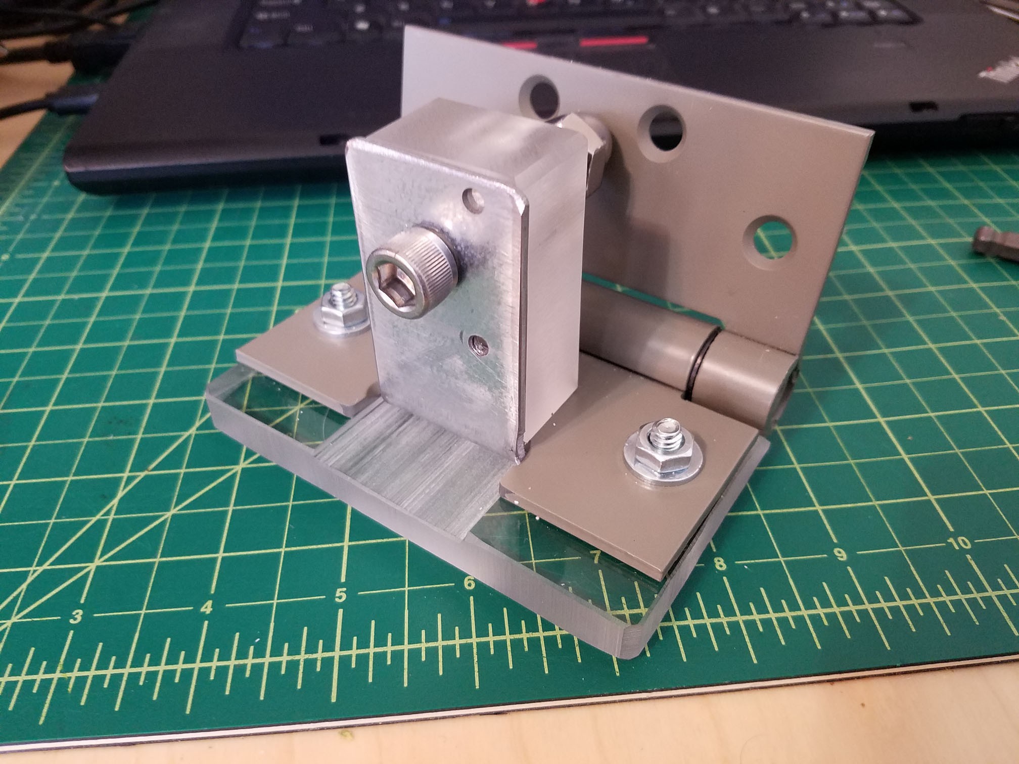
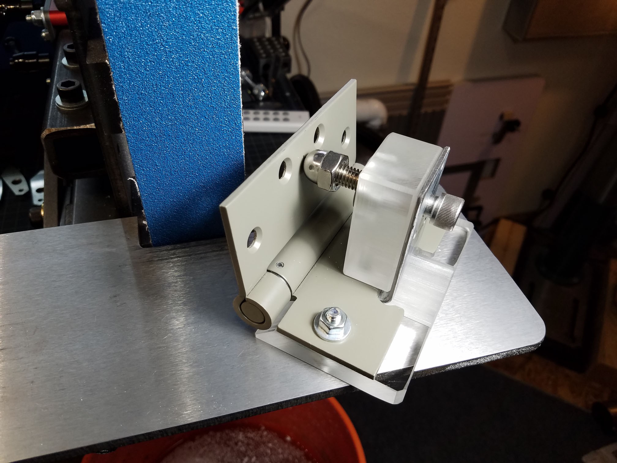
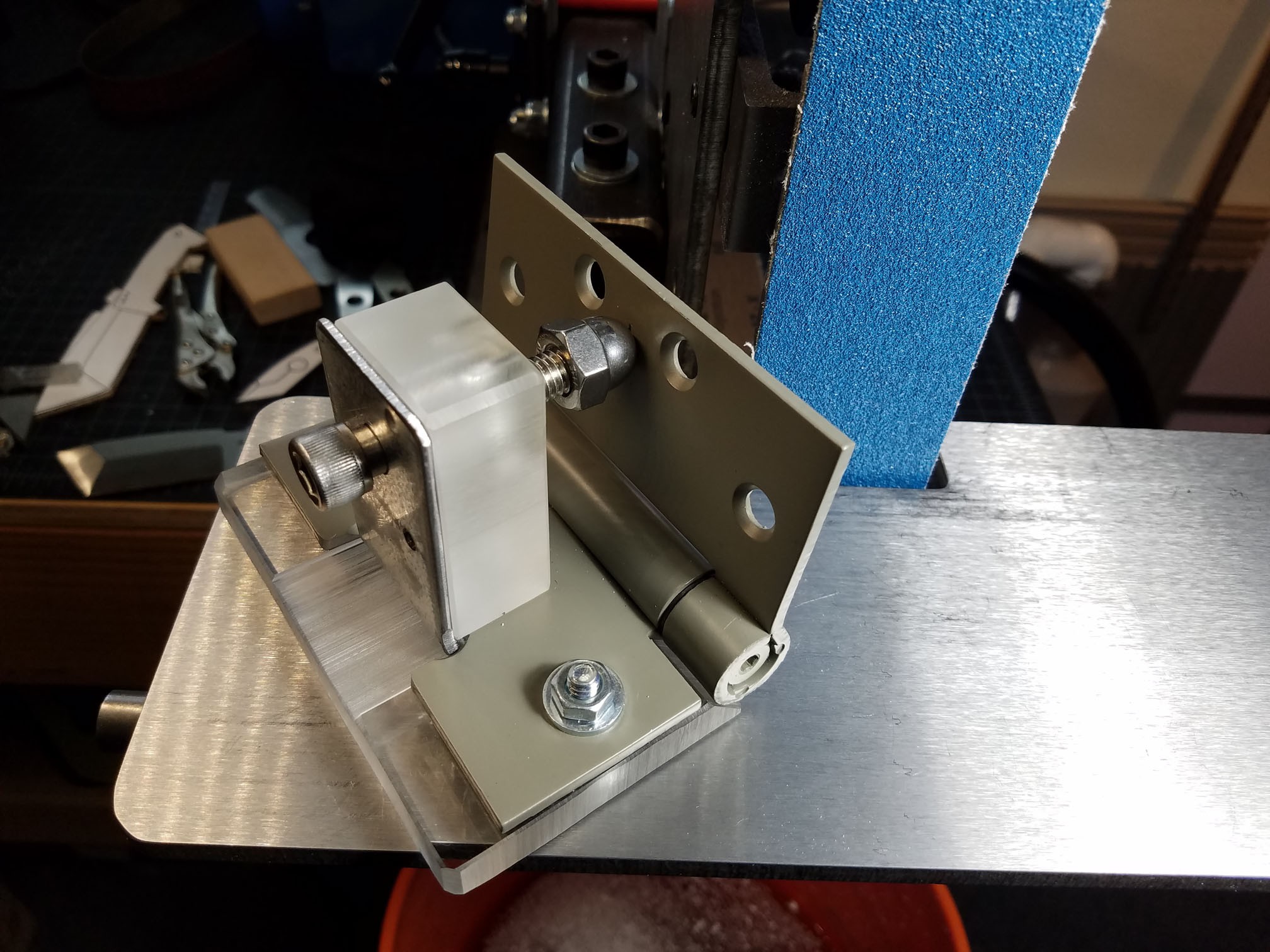
All that was left was the final assembly. Insert that last screw, add the cap nut (I stuck a tiny screw into the cap nut first so it wouldn't screw down all the way, giving me a bit more length), and setting up the spring inside the hinge.
I was especially happy with how the final screw held everything in place. It screws through the base, through the angle bracket, through the hinge, and into the thick plastic. The thick plastic is connected to the angle bracket again with the main screw adjust, so everything is held in place quite securely.
I had never used a hinge like this before, but it was really easy. Use the included allen wrench to tension the spring in the opposite direction as you'd like the force to be (I gave it almost a full rotation so it was tight), and drop an included pin into the pivot to hold it in place. The spring tension will hold the hinge against the cap nut, holding the angle in place.
![]()
![]()
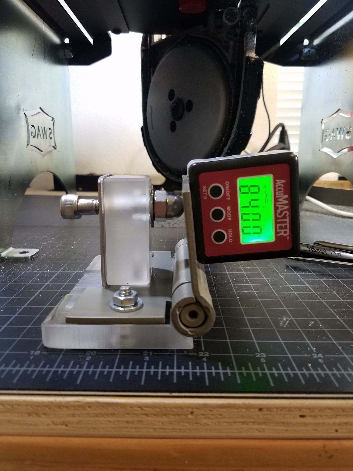
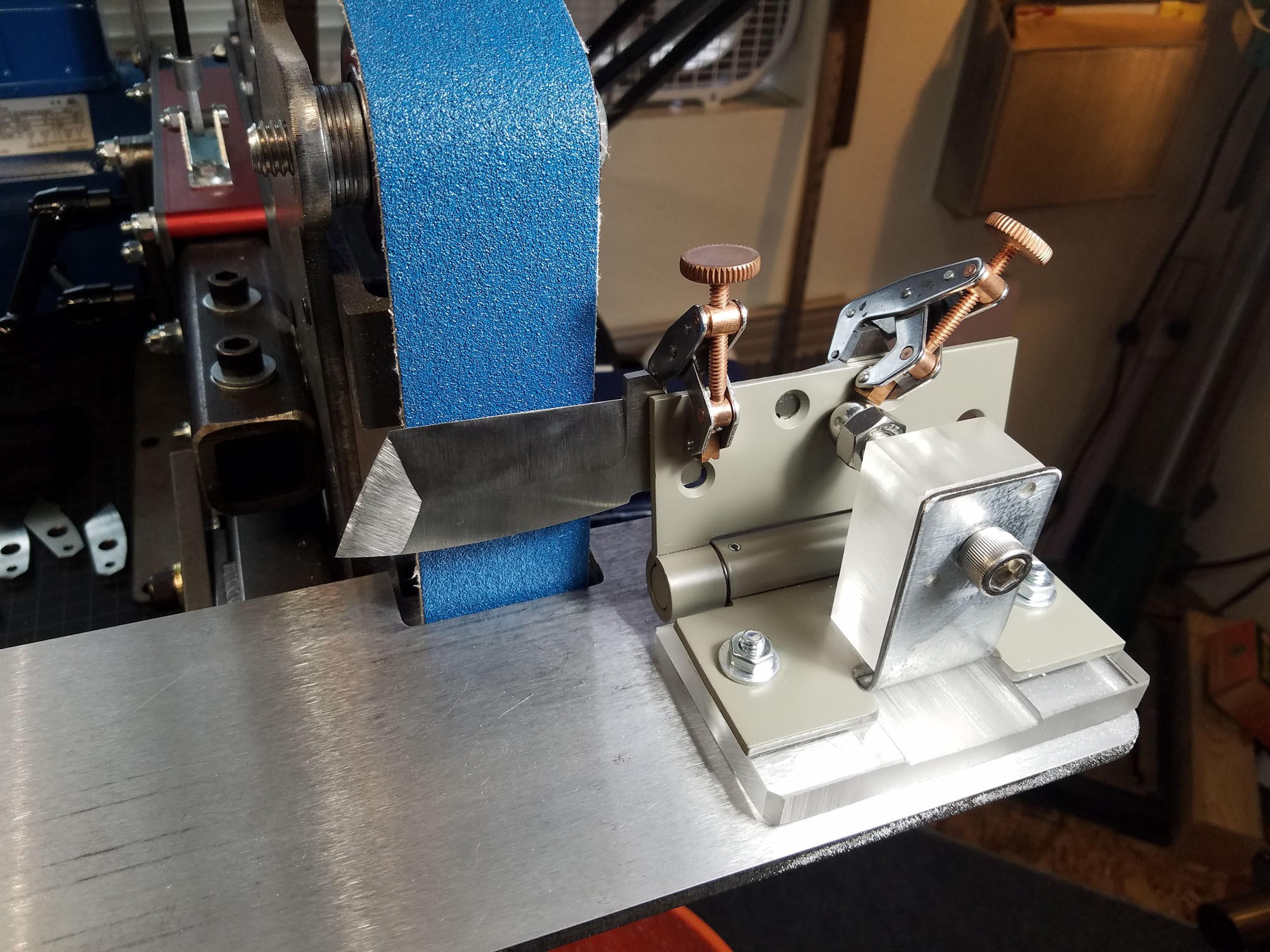
With this setup, I'm given 6° of acute deflection and 13° of obtuse deflection. I'd like to get another screw to increase the obtuse deflection (I want to get at least 20°), but this will get the job done for now.
![]()
![]()
![]()
![]()
![]() For use, I set the angle using my digital protractor (shown above) and clamp a knife to the jig using Kant Twist clamps. This helps to hold the knife at a proper angle to grind the blade, and holds it in a stable position to give a nice clean finish. The plastic base is perfect for sliding cleanly against the tool rest.
For use, I set the angle using my digital protractor (shown above) and clamp a knife to the jig using Kant Twist clamps. This helps to hold the knife at a proper angle to grind the blade, and holds it in a stable position to give a nice clean finish. The plastic base is perfect for sliding cleanly against the tool rest.![]()
Adjustable Angle Knife Grinding Jig
Adjustable Angle Knife Grinding Jig made from $27 in hardware store parts and some scrap plastic I had at home


Discussions
Become a Hackaday.io Member
Create an account to leave a comment. Already have an account? Log In.