 Fox
Fox-
1Step 1
Assuming you now have all of the parts available at your disposal (plus a few spare just in case - you know how sods law is). Start with looking at how you are going to lay out the parts and wire/solder them up.
![]()
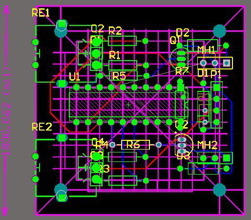
I probably went overboard by using a circuit board editor and actually creating the layout for my prototype board. At least by doing this I could see how large the components would be and how they would sit.
Comparing with the actual parts also helped in laying it out cleanly.
All else fails, scratch it up on a piece of paper. In the above pic, blue runs were mainly component wired. Red runs were with CAT5 copper wire. -
2Step 2
Now you know how this is going to look and is a layout you are happy with. The next step is to wire up the AVR micro into a breadboard and use jumpers from the correct ISP pins to connect to the programmer. Consult the datasheets for the correct pinout (I might expand on this later).
NOTE: When programming, ensure you untick the CLKDIV8 fuse otherwise it will only be at 1MHz - and be too slow for a decent PWM to the fans.
I took things a step further and wired up an encoder and a LED off of the corresponding PWM Channel, just so I could see the dimming/brightening of the LED. -
3Step 3
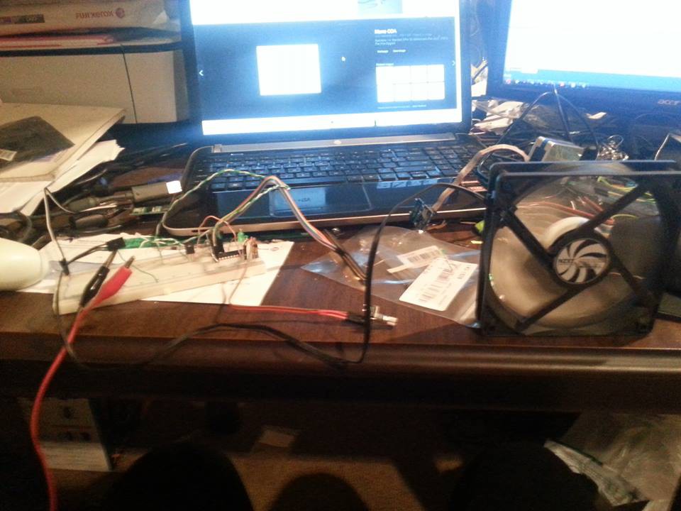
Now that you've used the attached code (I'm going to assume you have anyway...) have a play if you like to ensure all is going smoothly.
This is everything hooked up on a breadboard.
![]()
Otherwise, it's time to assemble the finished product!
-
4Step 4
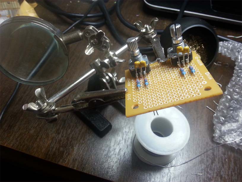
Start with soldering the Encoders onto the board. This where a pair of helping hands works wonders. Alternatively use a block of wood with a clip board clip nailed to it to hold the board as you solder each of the components.
The fiddly part is soldering the Capacitors onto the encoders.
![]()
Make sure you do not burn your fingers! It hurts!
Next add the 10k resistors.
-
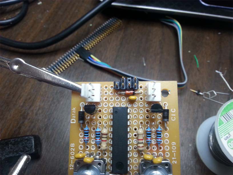
5Step 5
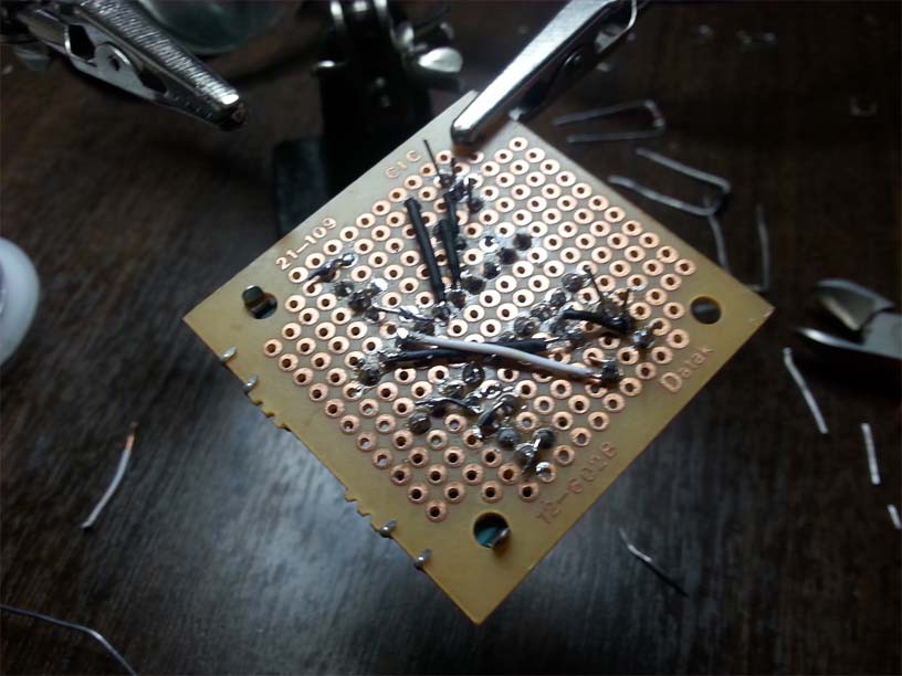
With the resistors soldered down, the leads facing the encoder can be bent and soldered onto the encoders. Chop off the excess and solder in the ATtiny, the resistors that are tied to the PWM channels and the transistors.
![]()
-
6Step 6
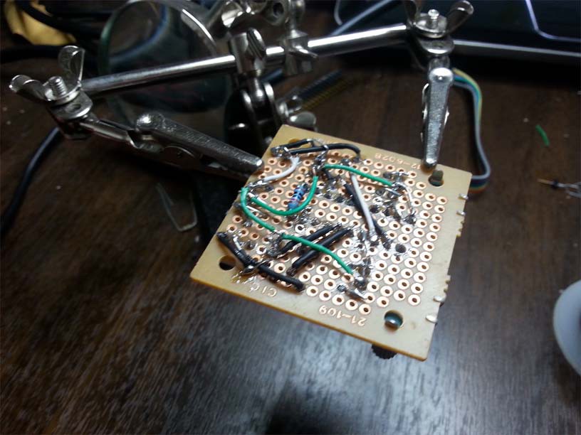
Things are starting to take shape now!
Flipping the board over, the connections for the encoders can be made with wire. Just make sure you have the encoder linked to the right set of pins, otherwise when you turn the knob you'll be altering the opposite side's PWM!![]()
-
7Step 7
For the 4x2 header, you can see here I've removed two of the pins. One with plastic missing to help identify which way round. The open hole provides a place for the notch protruding out of the connector to sit firmly. Make sure you take note of this before you solder it in +12 far left, +5 volt far right (please ignore the other components - I ended up taking this photo after finishing).
![]()
-
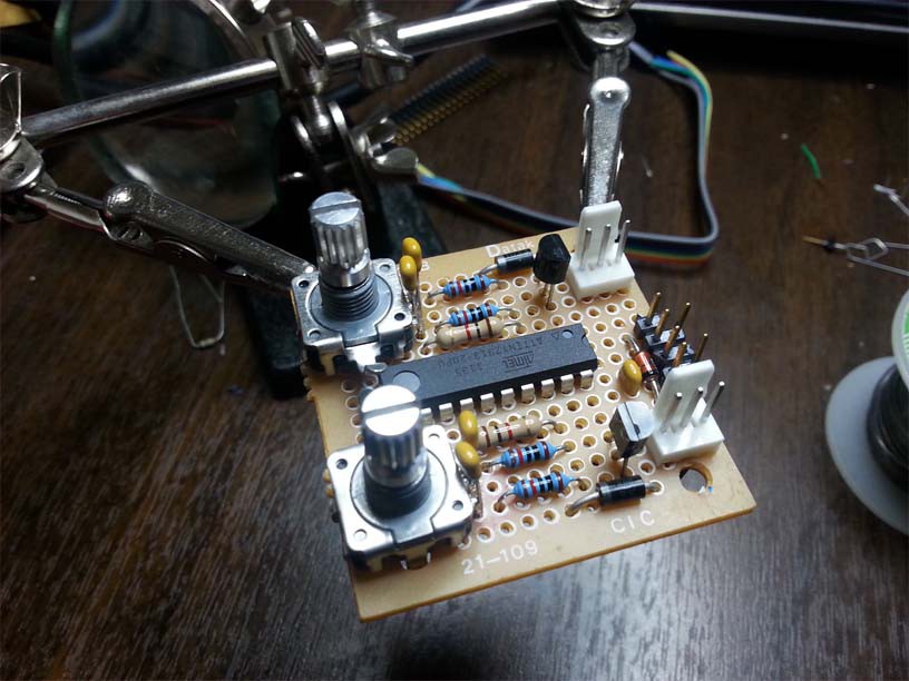
8Step 8
As seen on both the schematic and the 2313 datasheet, the RESET pin and VCC pin are at the top of the DIP package. Solder them together with the 10k pull up resistor. Put the rest of the through hole components into the board, joining them together as and where required. Cut off the excess then solder in the ground cables.
![]()
-
9Step 9
Solder in the +12V connection to the two fan connectors (the middle pin) and the +5V pin to the VCC pin on the microcontroller.
And there you have it!
One complete 2 Channel PWM 3 Pin Fan Controller.
![]()
Just for safety and to ensure nothing shorted inside the PC case I covered the bottom with black insulation tape (hey I did say cheap!).
Cheap PC PWM Fan Controller
A two channel fan controller utilising an Atmel AVR ATtiny2313 and Rotary Encoders.

Discussions
Become a Hackaday.io Member
Create an account to leave a comment. Already have an account? Log In.