 Boelens, Leland
Only two 26 guage phone cable wires in one available pair, from outside to the Phone equipment room, where 4 wires are needed, and 2 really need to be 16 guage or larger. No room in a 1/2" conduit also.
So I put on my thinking cap and was determined to find a solution to using the only 2 wires between the 2 locations the wire needed to be.
I thought the only thing that could perform 2 contact closures one at a time using 2 wires would be one that could sense the polarity of a DC voltage. Also with the wires carrying no voltage until the 5 seconds of activation would last a whole lot longer than wires carrying voltage in outside conduits.
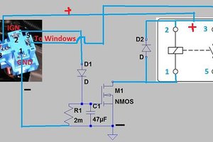
A DC relay would provide a contact closure and isolation from the device being controlled. Also a diode connected in series with one relay lead would make the relay polarity sensitive, like positive for one and negative for the other.
The polarity reversal could be accomplished by a DPDT relay in the phone equipment room. The DC power supply would power up all three relays from the phone equipment room.
The logs document all the steps involved in getting all pieces tied together.
The background photo above is this same circuit used on a training board I designed to educate the technicians on DC relays, diodes for polarity, and another task to install a spike absorbing diode across the relay coil without causing the switching regulated supply to go into shutdown. Also if the switching supply was disconnected and reconnected with the polarity reversed, the power LED would light red. This photo shows the LED yellow, it should have been green. The color change is from a 2 lead dual color LED, one polarity is green, the other is red. It is assembled with a series voltage drop resistor and two 14 volt zener diodes wired in series with their cathodes connected. This provides a 14.7 volt drop across the zener diodes regardless of the polarity, the LED drops approx 3 volts and the resistor the rest from a 24 VDC switching wall adapter. I liked the really big 24 Volt contactor for the training board, so it set the voltage for all the board relays.
The jumper wires in the photo above are properly wired to connect the DPDT relay to the two remote relays on the right. The center off toggle switch is in the down position, powering the DPDT contactor coil. The contacts have moved to the Normally Open contacts and the Red Led is lit on the lower relay on the right.
The dual banana connectors carry the spike absorbing diode. The DPDT relay and the polarity sensitive relays are connected so that when the center off toggle switch is up the DPDT Normally Closed contacts are made and the center off toggle will complete the circuit to energize the top relay on the right. The center off toggle switch represents the 2 Normally Open contacts to operate this circuit, but on one toggle switch to maintain that both relays are off when off, and that only one relay is on at a time.
 justin.richards
 Silícios Lab
 bryan.lowder
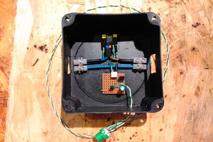
 Szabolcs Lőrincz