Chris Chung
-
Other PCB Candidates
04/30/2021 at 18:21 • 2 commentsOther PCB Candidates
Over the last few months, I had gone through 3 PCB designs. The hardware debugging is mostly done.
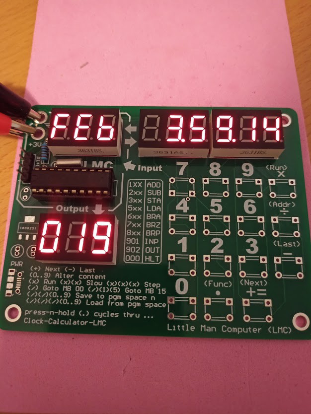
I am waiting for a "final" PCB design. There will be 15 tactile buttons, 4 units of 3 digit 7 segment LED display modules, and powered by one AAA 1.5V cell.
The design is focus on the following factors:
- Pocket size - smaller footprint, fewer buttons, single battery.
- Standalone sustained operation - battery power, AAA instead of coin cell.
- Simple construction - few and common components.
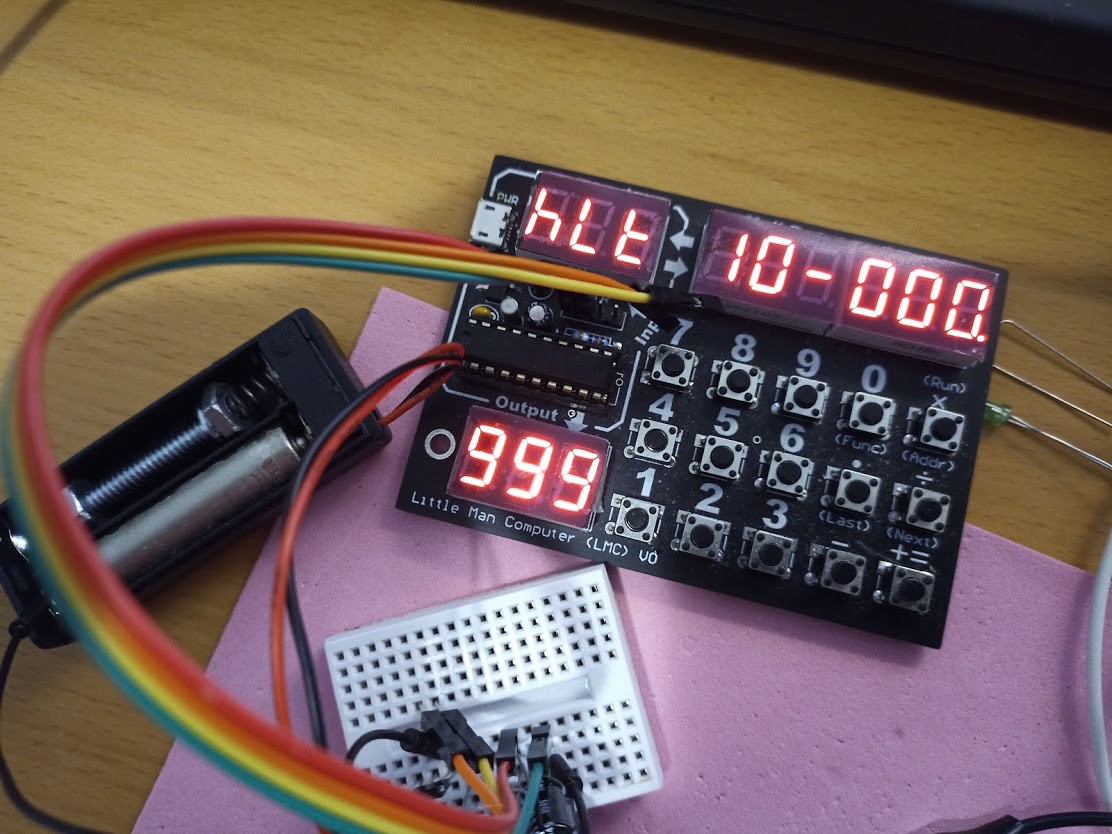
This one turned out to be too big to fit in a shirt pocket. Also it is not battery powered.
![]()
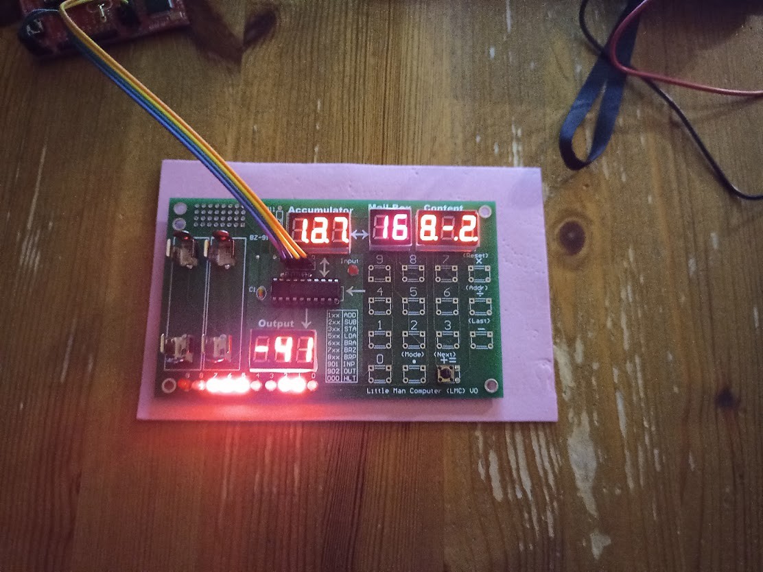
This design has 2 x AAA battery for power. Overall it is too large.
![]()
This design is small and compact and USB powered. I had order another PCB powered by 1 x AAA cell. Hopefully that will be the final design.
![]()
-
Hardware Option #1
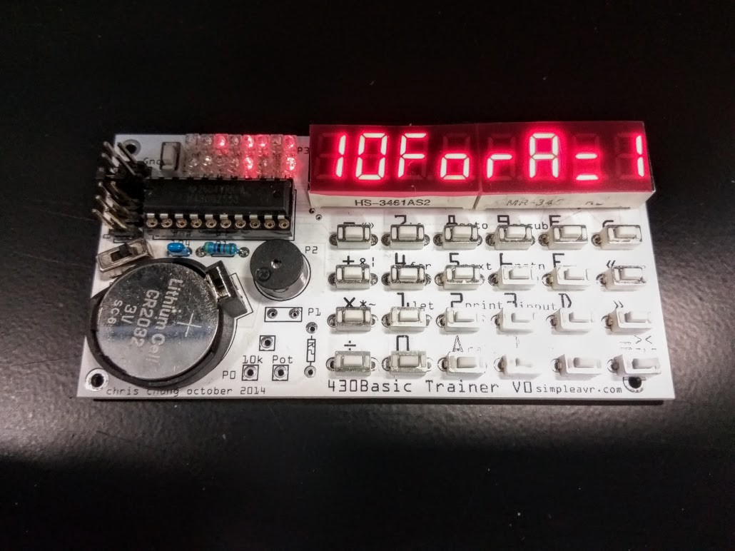
04/27/2018 at 12:25 • 0 commentsI am trying different hardware designs. This one design I might adapt is from a "basic" trainer project that I started and not finished.
![]()
This PCB design has all components on one side of the PCB. It also contains some extra IO options for the user to experience with. The exposed components will be attractive to a kit builder / hardware person. And it may not be ideal for an everyday carry pocket device.
This design full-fills the LMC trainers input and output requirements, plus extra
- 4 IO pin breakout via header
- 16 LED bit display for registers
- Buzzer
- Potentiometer for ADC experiments
The little man computer instructions 901 (INP) and 902 (OUT) accepts input from the keys and output mailbox values to the 7 segment displays. An ideal is to introduce additional IO instructions, say 9xx for additional IO components. Ex. We can have 903 for input via ADC channel 1 (hookup to a light sensor), 904 as output to a 8 bit LED display.
This will allow more hardware elements to interact w/ the LMC language.
There are additional designs that I need to try out before fixing into the final.
Little Man Computer Trainer
This is a low power pocket computer trainer for the Little Man Computer (LMC) computer model