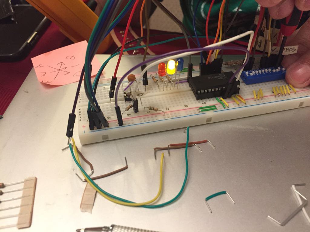
The EEPROM was manually programmed using a basic breadboard circuit. This system enabled simple programming, but might be impractical given enough inputs. As built, the system supports six (6) switch inputs with three (3) outputs. This required the programming of 64 entries. The number of entries is simply a function of two to the power of the number of inputs (2^6 = 64).
LEDs were used to provide a visual indicator of the output levels being programmed. DIP switches were used to select appropriate address values. An RC circuit and momentary switch were used to achieve the necessary specifications required by the EEPROM datasheet to communicate a write mode.

 Jon
Jon
Discussions
Become a Hackaday.io Member
Create an account to leave a comment. Already have an account? Log In.