Walter Dunckel
-
A look back, a new test chamber, and Level 1 Cert
12/16/2016 at 06:37 • 0 commentsOne of the main goals of this 9dof tilt sensor rocket altimeter, was to see if tilt sensing could be used as apogee verification for future chute deployment circuits. Looking back at the data from the successful flight, I was curious to see how closely the altimeter apogee data lined up with the 9dof tilting apogee. Tilting apogee occurred within 2.5 feet elevation in comparison to the altimeter data. It was also within about 0.3 seconds. It looks as if the tilt measurement will be a very good secondary check to confirm reaching apogee, but more test data is needed.
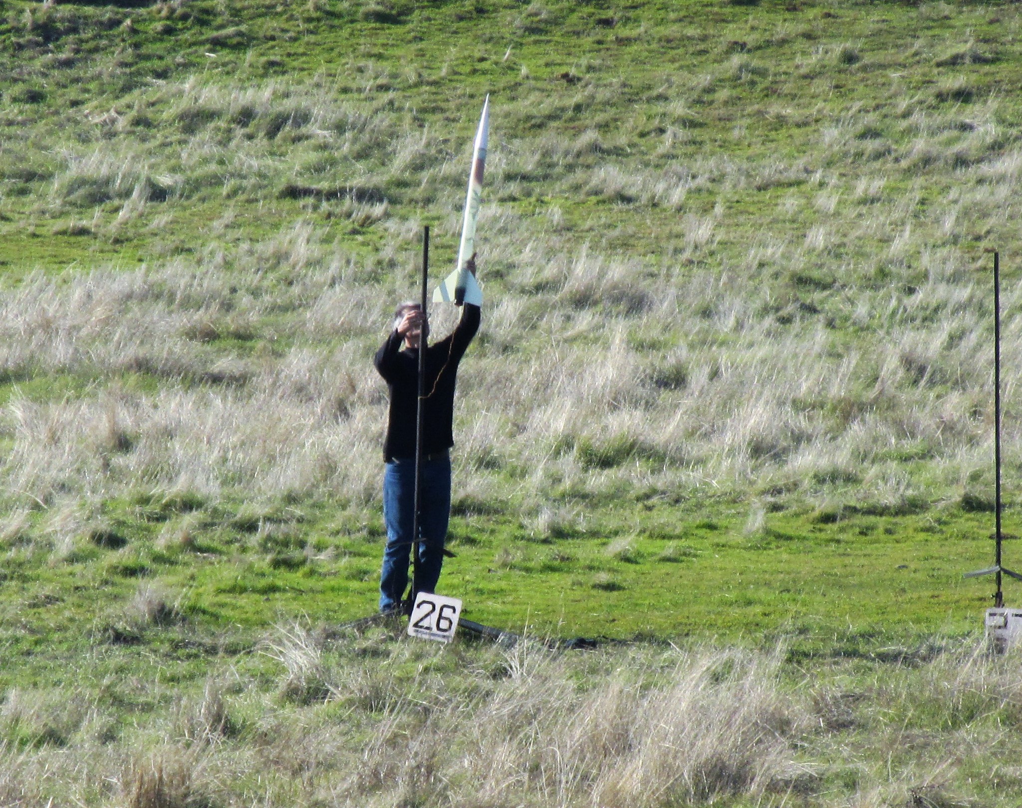
Lunar.org had another rocket launch in December. I attended, with the goal of getting my model rocket high power certification level 1, and also getting more flight data. I did certify on a conservative H238 rocket motor installed in a Mad Cow fiberglass 2.6" Black Brant II rocket to an estimated 1700 feet. So I am now allowed to fly and buy H and I motors.
![]()
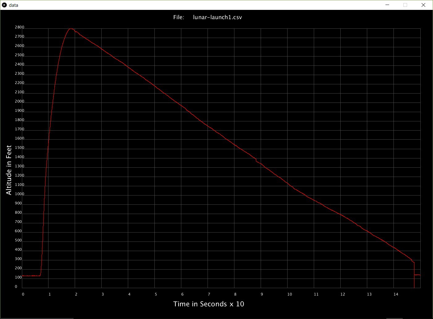
I had issues getting my altimeter to communicate prior to any of my flights. (I have since gotten them to communicate,and it looks like it was due to me not using the correct version of arduino code, and processing code). I then put my Altus EasyMini altimeter in my Aerotech rocket. The electronics karma was not not with me that day, and the 2700 ish foot flight showed up as a mere 431 foot high flight, with some very strange acceleration graphs. I believe I may have had a loose connection on the battery circuit, and it rebooted mid flight.
![https://cdn.hackaday.io/images/61691481874132900.jpg]()
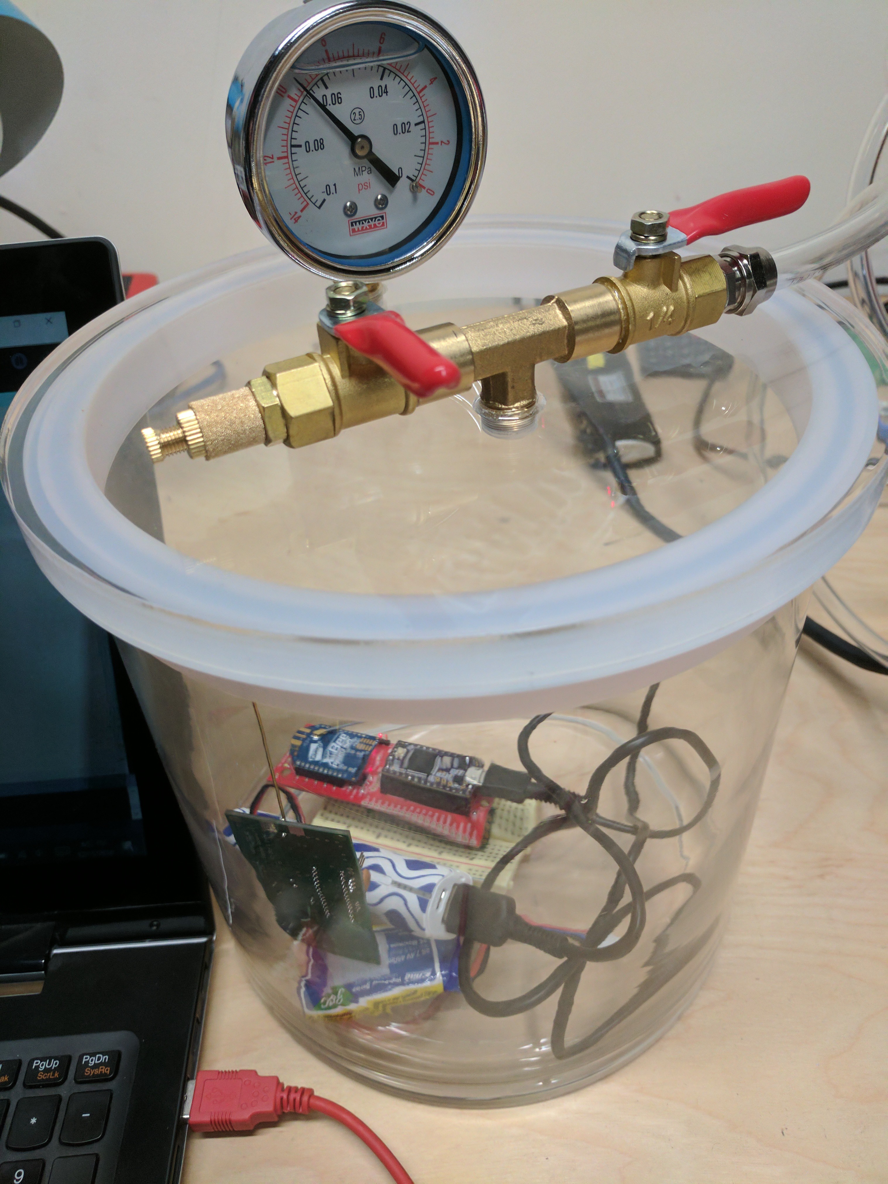
UPS delivered my new vacuum test chamber today, and I got a chance to vacuum it down in excess of 30,000 feet. I used an Eggfinder TRS altimeter for a quick comparison of the altimeters. Interestingly enough, the Eggtimer TRS did not seem to like being that high and proceeded to display negative altitude. I then brought the pressure down to 25,000 feet and they differed by 130 feet at that altitude. I compared a few more readings as I let some air return back into the chamber. In a quick comparison, the readings looked similar further down in "altitude". I have also performed a similar test with with the XBee vs the Altus EasyMini, and the results are similar. This test chamber will be used to verify chute deployment circuits proper function as they are added to the programming. That way they can be tested extensively, prior to putting the unit into the rocket.
I have gotten to play with the Eggtimer TRS altimeter with LCD and bluetooth module, and the compatible RocketFinder phone application for a while now. Although this combo has very slow data transfers compared to xBee, the functions it does have are very nice. While I had originally thought that laptop operation would be optimal .... I have since changed my mind, and now think that a cell phone rocket interface would be closer to ideal. A couple things that brought me to this conclusion (besides just playing with the Eggtimer TRS) was 1. My computer screen is almost unreadable in sunlight. A cell phone is better built to handle that. 2. I saw my friend pick up his laptop and walk over half a mile to retrieve his rocket, using his tracking software. Although it worked perfectly for him, a cell phone is so much more portable. So I am going to pursue programming an interface, so that a connected xBee, or a xbee connected to a bluetooth module, can be used to view rocket position. I would not try to reinvent the wheel, but I want to add functions like arming and setting main chute altitude to the functions that RocketFinder has.
Been trying out the new Arduino 1.6.13 version, with the new Teensy version 1.34 beta 1. The new Teensy version has options for code optimization now. While some appear to be compatible with my firmware, the new LTO options do not seem to work. With optimization set to "fastest" everything seemed to work, but will test some more.
-
Got a real test flight in
11/06/2016 at 06:09 • 0 commentsToday my local rocket association ( wwwl.lunar.org ) had a launch I was able to attend. The skies were clear, and not much wind to speak of. It was also great to see a bunch of larger rockets.
For the ground station, I wanted to get a boost with a directional antenna to reduce the possibility of loosing data. I found that one of my older wifi access points had an internal panel mount antenna that was good for 9 db gain. It also happened to have the same connector as the digi transceiver.
I put the antenna on the grass - pointed upward and hooked it up to the laptop. I started recording the telemetry as they announced each rocket prior to launch. As the rocket accelerated, I glanced at the computer screen and saw that it was busy gathering flight data.
Looking over the data I can see a few places where data was missed, but overall, it seemed to work very well. The biggest piece of missing data is when the rocket reaches the final 100 feet above ground level. Part of this was NOT line of sight, and I had pointed the antenna straight upward, so it was pretty impressive to me that it received all but the last 100 feet AGL.
The virtual flight is pretty interesting to me. You can see a lot of rotation in the rocket. This rocket has pre-cut fin slots, and I made no attempt to angle the fins, but obviously they are not straight. The rocket bobbles a little before the parachute opens, and then the nose cone sways beneath it. Perhaps the ejection charge caused some of the strange motions just past apogee.
I had assumed that the 9dof sensor fusion would be majorly confused by this high rate of acceleration, and possibly do strange things to the orientation result. However, I am quite pleased with how it turned out. I appears to be pretty accurate, and apogee is obvious
A second launch was made, however, the telemetry ran out of battery power, so no data from the second launch is available. Below is a graph of the recorded flight:
![]()
-
Graphing data from a csv file using Processing
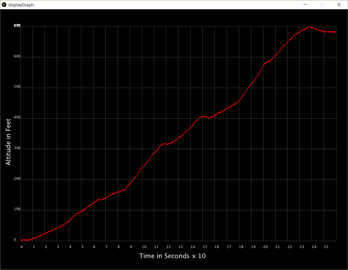
10/23/2016 at 19:18 • 0 commentsSpent some time getting graphing working to read altitude from a sample csv file containing over 26,000 altitude data points. The csv file was collected by my hardware, and logged using my laptop while driving over a hill. After pulling my hair out for a while, I realized processing did not like the spaces between the data points. I edited them out, and will be changing the firmware so it just sends a comma between data points, with no spaces. I was a little worried that processing would be bogged down with so many samples, but I guess this is the type of thing Processing is made for.
Spent some time getting the graph to be happy with different size windows. So it is semi adjustable - just did not adjust font size. More of that could be done later. I tried to comment the code as much as I could to help me understand what it was doing. One of the things that first screwed me up was that the Y values of the graph are inverted. 0 is at the top, and the maximum is at the bottom. One of the neat things that processing has is a map() function. This places your value on the graph in the correct relative position, regardless of changes of window size.
Files are here: https://github.com/radiohound/NXPMotionSense/tree/Rocketry-and-RC-Telemetry
![]()
-
GPS Added to code
10/20/2016 at 01:55 • 1 commentAdded a small GPS (GP-735 https://www.sparkfun.com/products/13670 ) to the project, and used TinyGPS to decode the NMEA sentence. I played around a long time trying to get the gps commands to turn on and off different settings. Finally ended up using UBlox U-center software to send the commands separately, while listening to them with a Saleae Logic analyzer to help with the formatting. It is set to change the baud rate from the default 9600 to 115,200, and turns off every sentence except for GPGGA. This sentence gives Lat/Lon and altitude. That way the Teensy won't be trying to do too much, since I am making it read from the 9DOF and pressure sensor 100 times per second, as well as doing the orientation math, and sending all the results to the ground station over the radio modem. The GPS outputs data at 10 hertz.
Modified the ground station RocketNXP.pde to accept the lat/lon and display it on the screen and modified the log file to record that data as well. The data file is now named with a date and time stamp for the file name. A new one is created each time RocketNXP is started.
![]()
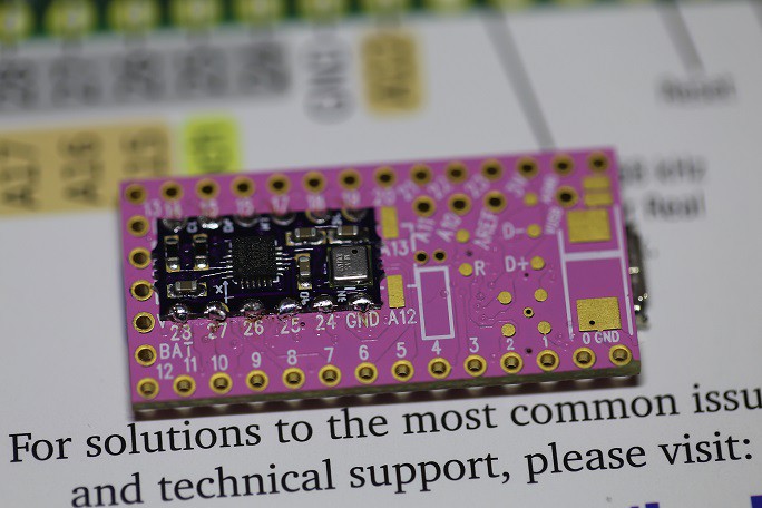
I ran across a few very cool products that I wanted to share. One is the MPU9250 9DOF sensor that is made to be soldered onto the back of a Teensy. Yes, this is small folks! It includes a MS5637 pressure sensor on board, because he had so much extra space left.
![MPU-9250 Teensy 3.1 or 3.2 Shield]()
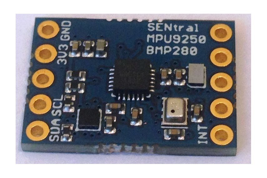
But what is very intriguing to me is his Ultimate Sensor Fusion Solution board. It uses the SENtral chip to take all the processing load off the Teensy. Unfortunately, this does not come in a form factor that plugs into existing pins, and must be wired.
But I digress ....![SENtral Sensor Fusion]()
I have tried the GPS on the freeway, and at 10 hertz it gives position updates at about every 8 feet (70mph). Sometimes readings to not update every 100ms, and can repeat previous readings one or two times before updating. The readings are time stamped by the .pde program, but the timing of them does not quite make sense. I need to do some more testing, and plan to use GPS time in the XBee data to help sort the issue out. Perhaps the program is doing something that interrupts the update of the GPS lat lon. However, the other sensors are getting their 10ms updates consistently.
After I sort this issue out, it's on to graphing altitude, etc.
-
On board altitude filtering and ground station based data logging
10/07/2016 at 05:09 • 0 commentsLast night I found simplified kalman filtering code for arduino here: http://orlygoingthirty.blogspot.com/2013/06/1-dimensional-kalman-filter-arduino.html?m=1 and added it into the project. It seems to work very well at smoothing a static altimeter, and doesn't bog it down like oversampling does.
Also got data logging to work from RocketNXP.pde. It now appends to a data.csv file, recording attitude and altitude.
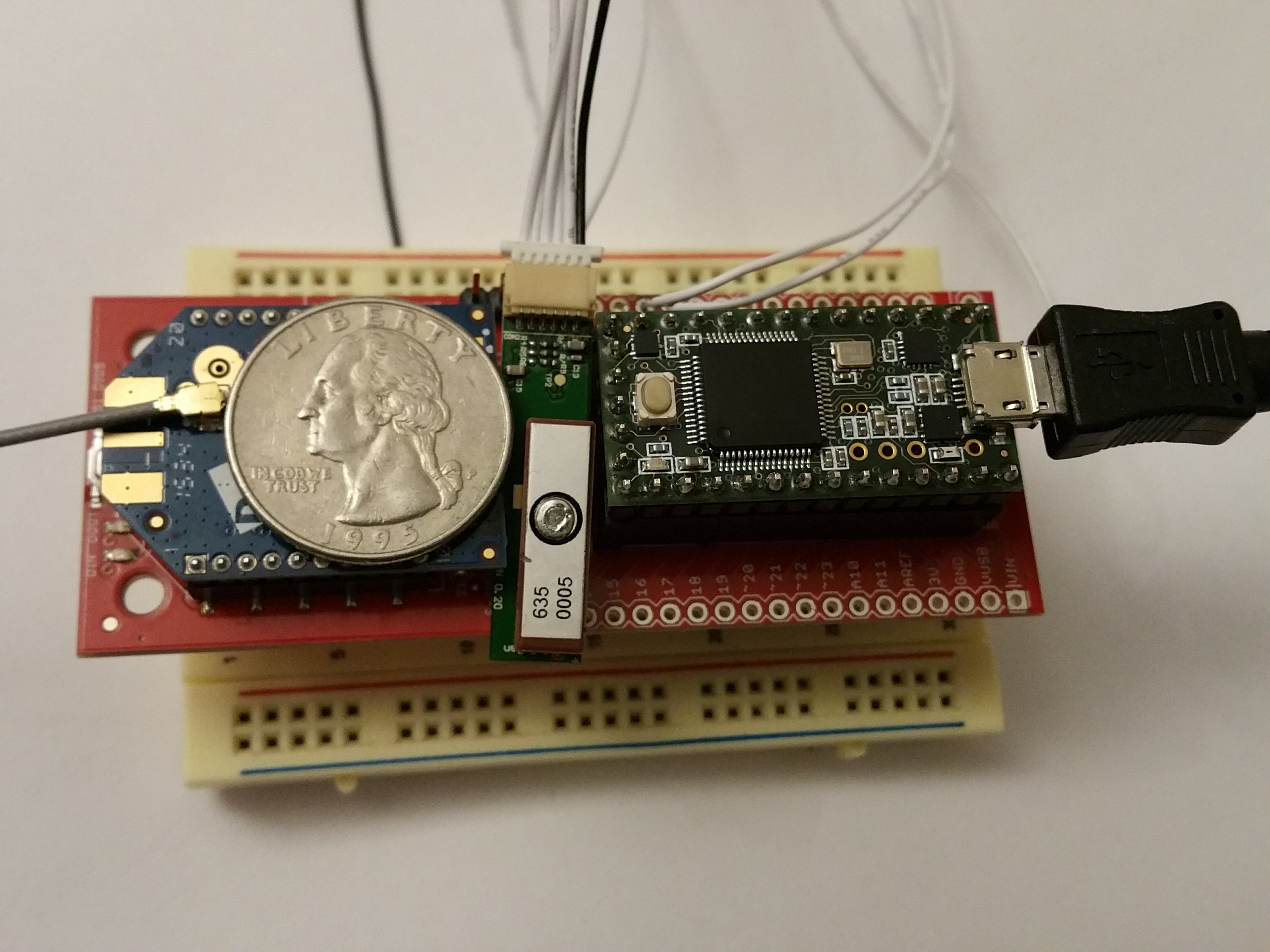
Today I received some backup hardware from Sparkfun. I did this mostly to make my hardware a little more compact, and save a little weight. Right now it sits at 0.8 ounces without the battery.
![]()
I may try to dust off one of my airplanes and see if I have any good lipos to fly the sensor around. Hopefully I can do a test run this weekend, while I wait, and wait ... for a legal rocket launch. There is plenty more for me to do. My to do list consists of the following:
1. Add GPS
2. Graphing of flight parameters like the AltDuino does. (His is really beautifully done) ... mine probably won't be that nice, but my code will be open :)
3. Modify the processing code to be able to play back data files and show virtual rocket's attitude during flight. Could be nice to review some flights, and shouldn't be hard, just reading from file vs serial.
4. Put it in a ROCKET!
And later ... add mosfet hardware for chute deployment
-
Artificial Horizon
10/02/2016 at 02:40 • 0 commentsfound some code pre-written for an artificial horizon written by Adrian Fernandez. I made some com port changes to the way it gathered the data, and it seems to work pretty well. It should be quicker for me to test in a model plane, than wait for a legal rocket launch (I am located in California). As it stands, flying airplanes with electric motors is against City code where I live. But I can drive 15 minutes away to a town that is more r/c friendly.
Anyway, here is a screen shot of the artificial horizon. I'll try to get a video in pretty soon.
There is some more fine tuning that needs to be done. I would like to add altitude to the right hand black bar on the horizon display, and with gps - add speed to the left black bar on the display. It would also be neat to make the horizon display a 3D globe, just to spruce things up.
-
Altitude tx and display added to code
09/30/2016 at 06:03 • 0 commentsAdded the sparkfun mpl3115 library and a couple lines of code to add altitude to the display. I'm not doing any over sampling of the pressure sensor, to keep the processing speed of the Teensy up. This caused the altitude to jump around a fair amout. Maybe I can over sample/fliter inside of Processing (the receiver side) to fix that.
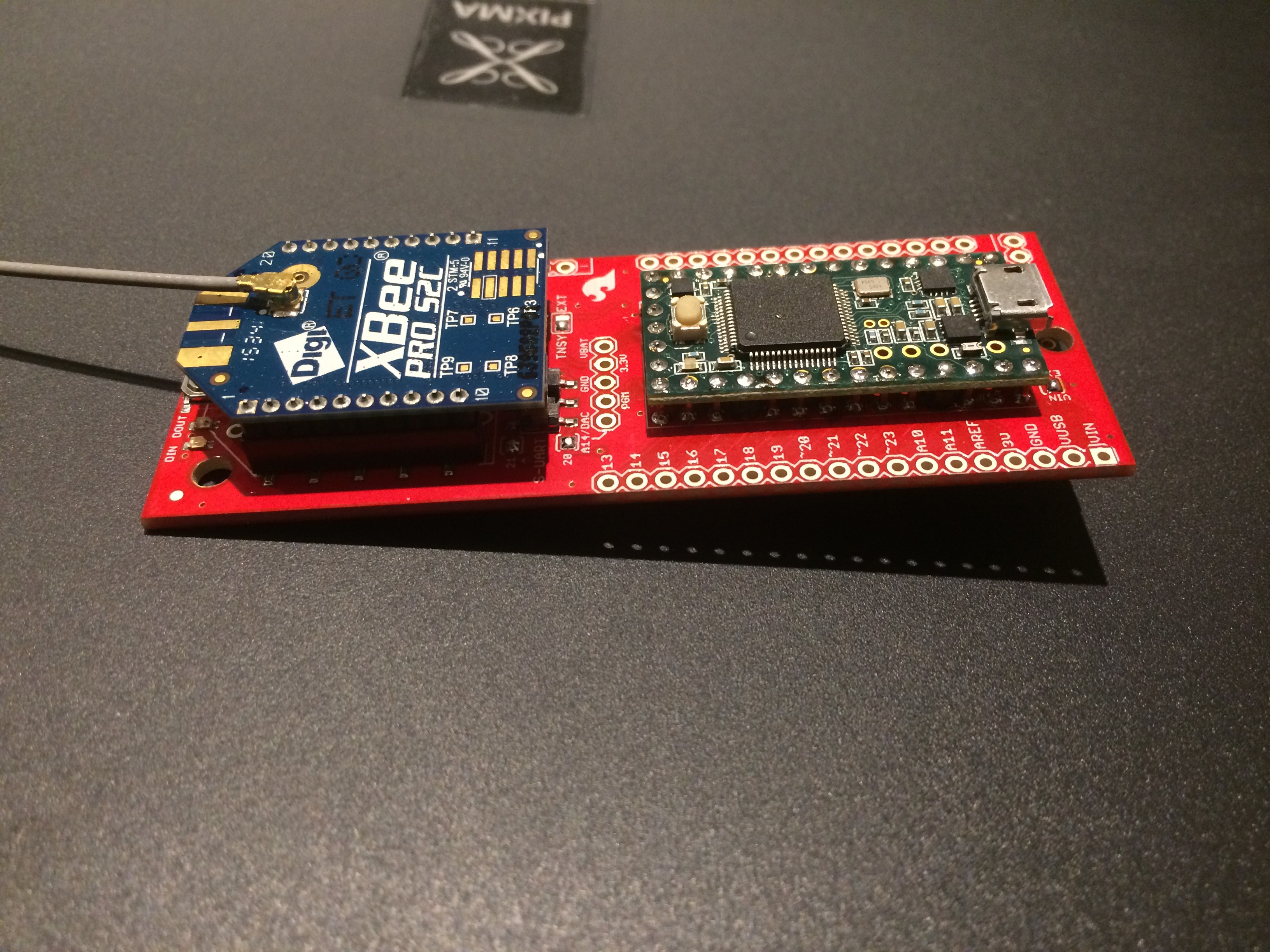
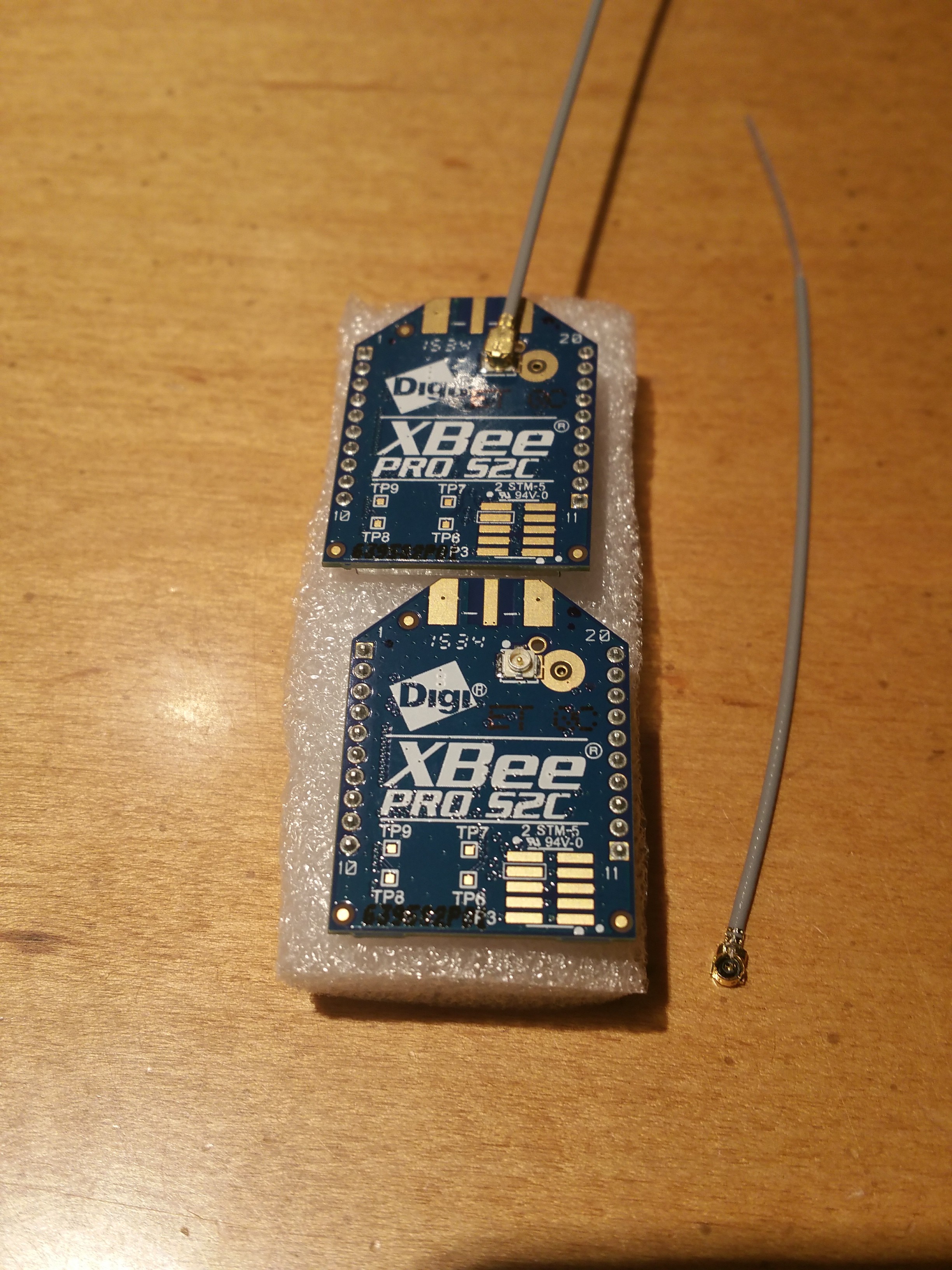
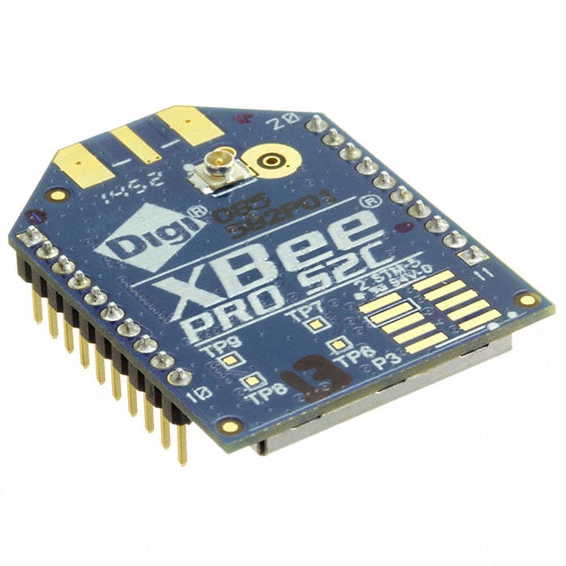
Also received the new XBEE Pro SC2 modules with external antenna option. Will make for better antenna placement outside the rocket tube. It would allow for easy connection to a directional antenna for the base station, but that may not be needed with the two mile range.
After some testing, these new XBee Pro SC2 modules with the Teensy, etc use 80mA while transmitting at full power. With the XBee Pro S1 modules it uses almost 40 more mA.
![]()
-
3D virtual rocket image, and wireless added
09/28/2016 at 05:08 • 0 commentsNew 3D rocket "skin" added to virtual display
Got the basic 3D rocket drawing in Processing working. Seems acceptable to me, with different colored fins to help see rotation. Also added in the wireless XBee transceivers. These only required a couple tiny changes in the code to make them work. Much easier than I anticipated (I have never used XBee's).
I did notice there is a cheaper XBee that transmits further, on less power. They also accept external antenna's. So I have put in an order for a pair. It is the XBee Pro S2C, and it's supposed to be good for two miles line of sight.
The large dark blue cylinder I'm holding is just an external usb batter pack. The battery I'll use for the rocket will be much more compact.
![]()
Rocket real-time transponder and GUI
My goal for this project was to use off the shelf components to build a real-time rocket altimeter on steroids at a reasonable price.