Quinn
Quinn-
THP Entry: System Design Document, Video and Requirements
08/19/2014 at 22:58 • 0 commentsThis log is intended to make clear all the entry requirement specifics in one place. Other log entries provide more details on the project and design.
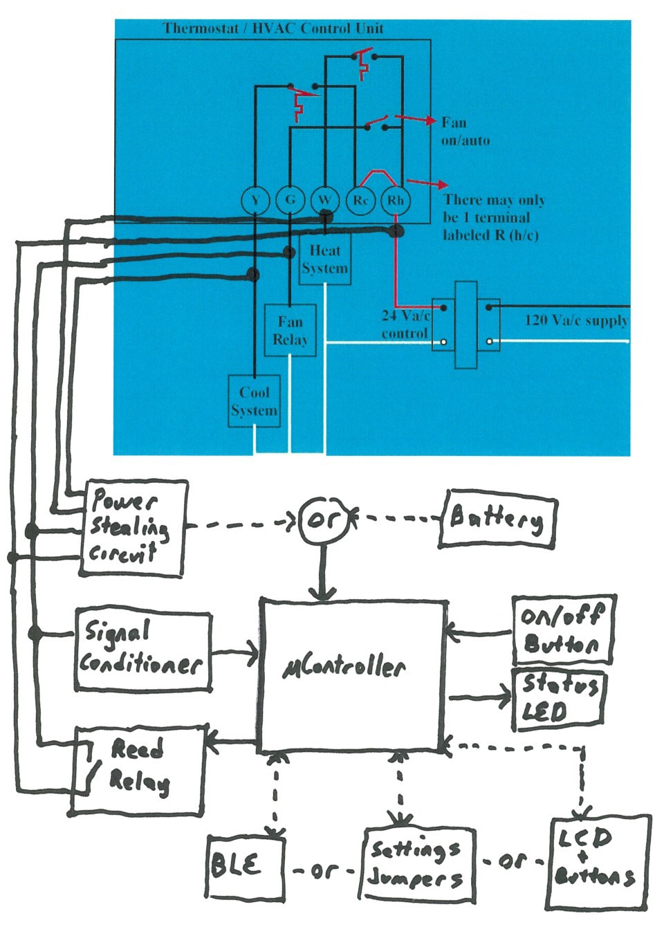
A block diagram of how it all connects is shown here: (System Design Document)
![]()
The first prize video is also linked on the main page links, and here.
Some comments on the contest requirements:
This is hardware and software project where a completed functioning module will be built.
The module qualifies as connected in the BLE version via bluetooth for configuration and status monitoring from a smart phone, tablet or computer. This is significant because it provides an easy to use interface for setup, as well as all of the advanced features discussed.
This project is being documented here, in build logs, parts lists and eventually build instructions. Schematics, software and images will be provided here.
This project is fully open hardware and open software, with everything needed to recreate it located here.
The module will be moderately easy for a hacker to recreate, with all parts easily available, low cost, and easy to use.
The resultant prototype can be developed into a manufacturable product in kit or completed form for mass sale and use.
The product directly solves a real world problem, improving temperature consistency around a house while conserving energy.
This project can be combined with other projects, such as a whole house wireless temperature monitoring system, or zoned system to create something new.
It is innovative in that it solves a problem in a manner that is not otherwise done on the HVAC market. No prior art could be found.
The basic model is extremely intuitive to use because it is hands and minds off once installed. The BLE version is also intuitive with an easy to use setup and monitoring app for smart phones, tablets or computers.
More details which make up the design document are in the following project logs:
-
Design: Controls
07/22/2014 at 19:02 • 0 commentsDepending on features being supported, different parts of a user interface are required.
Input: On/Off. This is required in all variations, and allows the user to turn the system off. This may be desired when away on vacation, or when servicing the HVAC system. It may be desirable to allow the user to tie this into an off switch on the existing thermostat, but this may cause too much complexity for some users to install, or vary too much based on the thermostat.
Output: On status. This is required in all variations. If the on/off input is handled with a slide switch, the visible state of the switch can cover this. Otherwise an LED that blinks occasionally(to conserve power) may be used.
Input: Cycle time. This is required in all variations, and allows the user to configure based on the attributes of their home. In the basic model, this can be dip switch settings. In a more advanced model with push buttons and an LCD or wireless, this can be set through that interface. The cycle time is the larger window of time that the minimum run time must be met during. For instance, this value could be 1 hour.
Input: Run time. This is required in all variations, and allows the user to configure based on the attributes of their home. In the basic model, this can be dip switch settings. In a more advanced model with push buttons and an LCD or wireless, this can be set through that interface. The cycle time is the the minimum fan run time to enforce during the cycle time. For instance, this value could be 6 minutes. In this example, the module would make sure the fan runs for at least 6 minutes every 1 hour. Looked at another way, there will never be a period of more than 54 minutes where the fan does not run.
Output: Fan status. This is desired in all variations, but may not be required. It could be an LED or other output that indicates if the module has turned on the fan.
Input/Output: LCD and buttons. This is optional, for advanced features. This would support an easier to use way to set the run time and cycle times, displaying on/off and fan status, as well as supporting scheduling.
Input: Remote temperature. This is optional, for advanced features. This would allow one or more remote sensors that the module could use to make a more intelligent decision about running the fan. As nominally described, the module simply maintains a minimum fan running duty cycle. With remote sensing(for instance upstairs and downstairs), the module could run the fan more or less depending on temperature differential between remote and local. This could be wired or wireless.
Input/Output: Wireless BLE Management interface. This is optional, for advanced features. It would allow connection of the module to a smart device or computer for controlling a UI for advanced features(setting run, cycle times, status display, scheduling, temperature reporting), as well as remote control. This would allow the more advanced features, while not requiring an LCD and pushbuttons. -
Design: Control logic
07/10/2014 at 16:46 • 0 commentsHere is the general program flow of the most basic module. Two timers, referred to as on and off, are used to keep track of time in states. These can be low precision so can be as simple as a variable manually incremented based on a timer interrupt.
1. Monitor the inputs. If the fan, heat or cool is on, reset off timer, and go to 1. Else:
2. Check off timer for compete. If not complete, go to 1. Else:
3. Start on timer, turn on system fan. Go to next:
4. If the heat or cool is on, turn off fan and go to 1. Else:
5. If on timer not complete, go to 4. Else:
6. Turn off system fan, reset on timer, reset off timer and go to 1.
In parallel to all states, check if all three input monitoring is low. If so, turn off the output, go into lowest power mode supported. In this case, the module is running off battery or hold up capacitors. This would happen if a system only has heat(or cool) so that the cool(or heat) input is open, then when the main thermostat turns on, the other inputs go to zero as well. Doing this just to retain timing and any settings. If this does not work on the basic model, it doesn't pose any issues, because when the main thermostat turns off, the module will power up again, and restart the timer.
In parallel to all states, monitor for user inputs and act accordingly.
For power savings, a system timer should be setup to drive interrupts periodically which wakes the processor, updates the loop, then goes back to sleep. -
Design: Interfacing the output switch
06/30/2014 at 22:33 • 0 commentsThe primary output of the module is to switch on the HVAC system fan. As described before, in a normal thermostat, this is handled with a mechanical switch, a tilt switch, or with a relay output from an electronic thermostat. This module will work in parallel to the existing thermostat.
The most robust and reliable way to interface the module to the system is to use a relay, with relay contacts wired connected to the fan control circuit. This is much more tolerant of various voltage and current conditions and provides isolation between the circuits, but it also is the option draws the most current. For example, a small 3V relay that I have on hand draws 40mA. As noted in the prior log, this is no issue if the C wire is available, but it usually is not. Running off a pair of AA batteries, for 6 minutes every hour, the batteries would last in the range of 25 days, which is poor performance. Some digging suggests that there are some reed relays on the market which draw 10mA(5V), and I found one which draws 6mA(3V), so with some careful part selection this may be acceptable.
Another way is to use a TRIAC to switch. This does not provide isolation, and has more failure cases, but minimizes the current requirements. Specifically, current or voltage spikes are more likely to damage the part, and it will not work in a system where a DC control voltage may be used. -
Design: Powering the circuit
06/27/2014 at 21:46 • 0 commentsThe prior log showed the common wiring of the control lines which gives us a basis to work from when figuring out how to power this module.
For convenience and reliability, it is much preferred if the add on module can be powered from the existing system, so that no additional wiring is required, no batteries to replace, etc. If the "C" wire is available at the location of the module to be installed, this is easy. 24VAC is then present and can be tapped off the C and R wires without issue.
If the "C" wire is not available, a method sometimes referred to as power stealing can be attempted, which pulls power through the heat/cool/fan control lines while pulling so little that it doesn't activate those circuits. This method is very dependent on the existing system. If those circuits are simple relays we can pull a moderately small current through them without activating the relay. How much depends on the relay, but some relays may allow in the range of 50mA, while others maybe only 10mA or less. However, if the control circuit feed a much lower current than a relay, these number go even lower, and may no longer be AC. That is, a more modern HVAC system control board may use opto isolators, so as little as 5mA or even 1mA may trigger activation, while the diode in it will remove half the AC waveform. It is for this reason power stealing will not work in every application. In situations where it does not work, the installation of a resistor in the HVAC system may make it work. Referring to the block diagram again, if we add a resistor across the heat system and cool system blocks, we can pull current through those resistors to power steal, but not activate the system.
If power stealing is used, it should be noted that if the circuit power is being taken from is activated by either this module, or the existing thermostat, this circuit is effectively shorted out, and no power can be drawn. The intended solution is to draw power from multiple channels, such as heat and cool, which are never activated at the same time. Capacitors or battery backup could also be used to cover over this time. If this is not possible, for instance in a system with only heat and fan, or with only cool and fan, the basic module may be able to still work. In that case, the module would be powered down, but upon shutdown of the HVAC system(when the thermostat is satisfied), the module will be powered up again and begin timing again. This use case will not be initially covered as a requirement, but kept in consideration.
The last method is to use batteries. Many thermostats on the market use their own batteries for this very reason, and frequently last multiple years.
A possible further method for exploration would be a solar cell and backup capacitors. Given the need for low current, this is doable with cells that are not unreasonably large, and operate on only indoor light, but the utility of this is questionable, so won't be initially explored.
The intent of this design is to support any of these methods so that it is more universal.
Supporting these however does mean that the module must run at quite small power levels, ideally averaging less than 1mA, but it may be acceptable to use more.
Using the direct wire input(via C and R wires), means using 24VAC, but to be more flexible, it means supporting DC, and a wider range of voltage to adjust for loss, or variations in systems. The wider range the better. Using power stealing has these same limitations, but also may result in lower voltages as there will be voltage drop across the HVAC relays. The simplest way to do this is to use bridge rectifiers from each of these sources, feeding a linear regulator. This allows quite low voltages to be supported, supports AC and DC inputs, but wastes power in the substantial voltage drop in the linear regulator. A buck converter instead of the linear regulator can reduce the current even more which increases compatibility, but adds complexity.
Powering from batteries is easier to implement, using a simple LDO linear regulator, or a switching regulator, again with the efficiency/complexity tradeoffs. It is possible that this circuit could be shared with the regulator used for the 24VAC input options, and could provide battery backup in case some of the more complex features of the module are included and should be backed up(such as schedule, clock, etc) during power outage.
The intent is to design the module to support as many of these methods as is reasonable to remain flexible in system support with one model of module.
All of these show that it is best to design the module to use the minimum current possible. There are a wide variety of microcontrollers which can run at very low power. The MSP430 comes to mind, and I have an eval board, so might go with it. Using an Atmega is another option, and has the advantage of easier development overhead under the arduino environment, but doesn't go quite as low current.(with aggressive use of internal osc at low frequencies and sleep modes gets it in the range of <1mA)
Note that this module is operating with a floating ground. This is required as it is being powered from an AC voltage, which due to variations in installation, it is unknown which wire(if either) is actually ground. What this means is that when compared to earth, the module may be operating at negative voltages, and/or that the potential of the entire circuit is varying with the AC input. This is fine, and generally safe, but it does mean that care must be taken to not ground anything connected to the module.(for instance, through the serial port when debugging) -
Research: How an HVAC control system works
06/23/2014 at 20:55 • 0 commentsThere are a number of variations in wiring based on what parts of a system are installed, as well as just how it is installed, but we can sufficiently generalize.
Wires come into the thermostat from the HVAC system. There is one wire for each control element, such as heat, cool, and fan. There is at least one additional wire to serve as the return. There may be multiple return wires, with separate ones for each element, or they may be combined. To turn on the fan, the thermostat connects the fan wire to the return wire. This is usually a switch or relay contacts. The same applies to heating, simply connect the heat wire to the [corresponding] return wire. Older mechanical thermostats simply used tilt switches mounted on bi-metalic coils to accomplish this.
It is because of this simple control method that this module can be wired in parallel to any existing thermostat. It will function simply as parallel switches; either one closed will active the system. The module will only be configured to control the fan circuit. The module can further monitor the voltage on the control wires to determine if the thermostat has switched on.
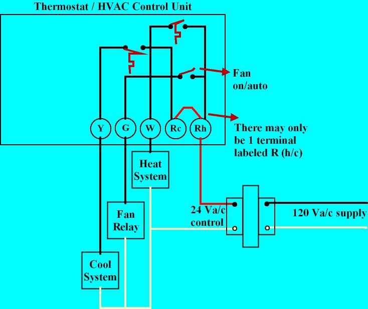
In block diagram form of the entire system, there is a 24vac output transformer which feeds power into relays which control the heat/cool/fan(white traces below). The other side of those relays go to the thermostat and make up the associated control lines(black traces below). The return line from the thermostat connects to back to the transformer to complete the circuit(red traces below). Here is a block diagram of the most common system from this link showing the switches in the thermostat, the transformer, and blocks for the heat/cool/fan relays:![]()
The control wires are commonly labeled as such:
- Y - Cool
- G - Fan
- W - Heat
- Rh - 24VAC for heat
- Rc - 24VAC for cool
- C - Common 24VAC
(Rh and Rc may be combined as simply R if the same transformer is used for both heating and cooling circuits)
These are all shown in the above picture. The white line on the bottom(24V side, not 120V) is the "C" wire. Note that this is an illustrative picture, and does not represent all the variations used in practice.
HVAC auto circulation
Stabilizing temperature around a home efficiently when heating/cooling is not required