Precision Indoor Positioning
Performing high precision indoor positioning using Vive Lighthouses, Arduino Due, and TS3633-CM1
Performing high precision indoor positioning using Vive Lighthouses, Arduino Due, and TS3633-CM1
To make the experience fit your profile, pick a username and tell us what interests you.
We found and based on your interests.
RawWatchmenData.csvThis is a data file with raw sensor readings. The first column is the entry in the ring buffer (it can be ignored). The second value indicates which sensor the reading is from. The third column indicates if the pulse is being asserted (0) or deasserted (1). The fourth value is the 84MHZ counter timestamp. The counter counts down, not up, and resets to 8,400,000. You can also find a spreadsheet that derives the pulse durations for this data set here: https://docs.google.com/spreadsheets/d/1VuC6vPGJbWWvgQUNDwA7uwgF-5N39R33YKEcbv24P4M/edit?usp=sharingComma-Separated Values - 4.87 kB - 10/19/2016 at 05:25 |
|
I've been working a lot with the libsurvive project to get this project going. It's very well aligned, and a small community of awesome hackers has converged on that project, as well as getting some unofficial support from the Valve guys from time to time. My main area of focus has been on finding the pose of a tracked object given the angle data from the lighthouse. This has been a much bigger undertaking than I ever imagined. I finally have pose estimation working at a somewhat usable level.
I'm willing to try different approaches to figure out the right mix of easiest & cheapest for the solution to this whole tracking problem. HTC was kind enough to send me one of their new trackers to test out. The tracker only supports sending position data out through USB, so the Due isn't a good choice here. Instead, it may be something more like a raspberry pi. We'll see. As for the software stack, the tracker should be a great fit with the libsurvive software stack. From what I can tell, it will look a lot like a Vive controller, although of course it has a different USB device ID.
So, I now have two lighthouses and a tracker. But no controllers or HMD. I feel like I'm starting to build a Vive system piecemeal.
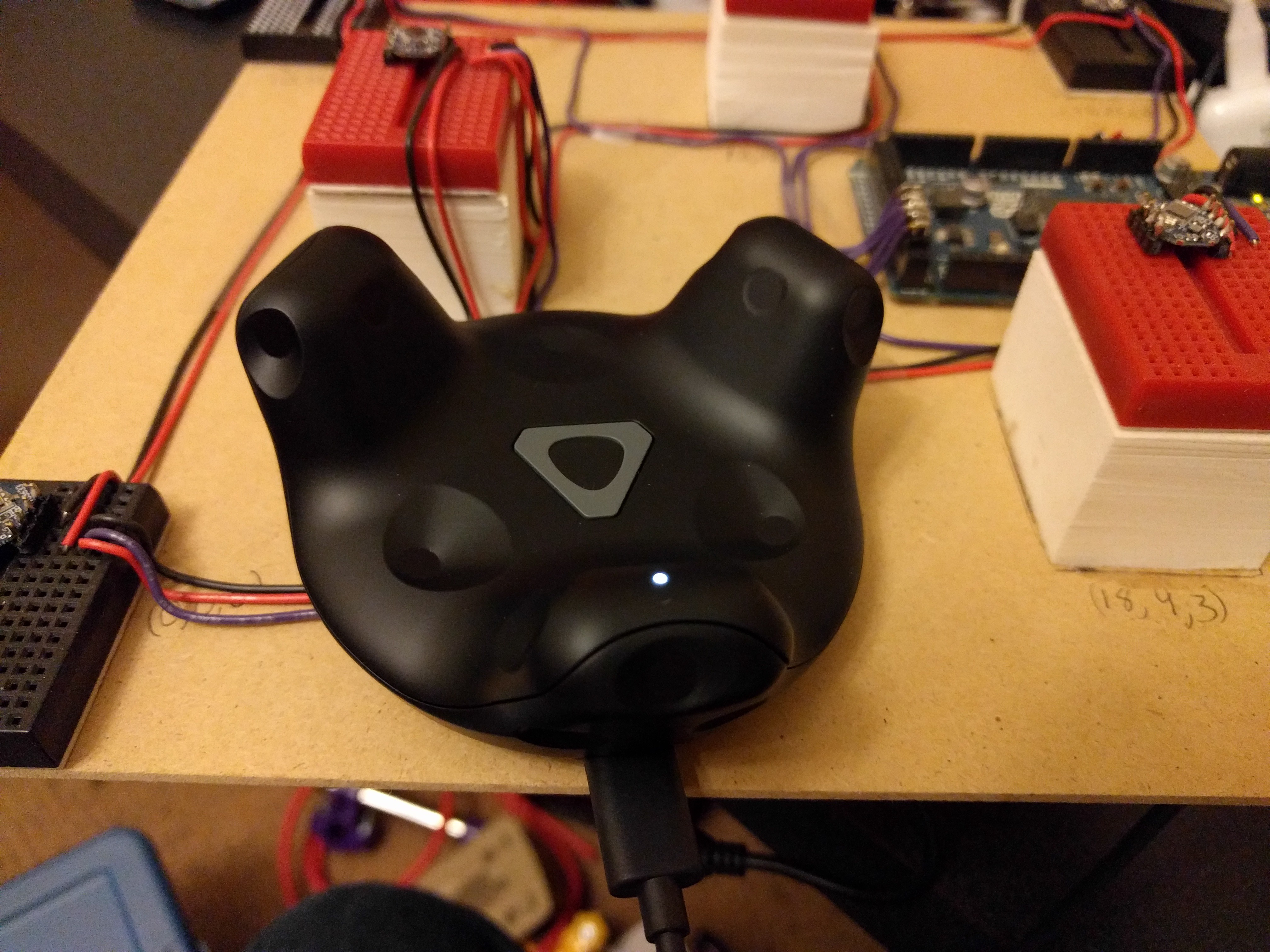
So, for now I'm focusing my efforts on getting this thing to work with libsurvive, as that seems to be the most promising path forward. I'm definitely not giving up on the microcontroller path long term, as I think it has a lot of promise, too. But a solution using this tracker would be much easier for others to duplicate in the near term.
It's been a while since my last log, but progress is being made. The big problem has been how to convert from point locations & lighthouse angles into a known position of the tracked object in space. The first part of that problem involves figuring out where the lighthouses are in relation to the tracked object. The libsurvive project is also solving much the same problem, so I've been working in the context of that project.
There are a number of ways to solve this problem, and it's not clear at this point which solution will work the best. The approach I'm taking is as follows:
Now, that sounds simple enough. But I'm not aware of any simple solution for finding the converging location for multiple tori, particularly when there is noise in the signal so they don't all converge perfectly.
So, here's my solution:
For each torus, generate a point cloud. Then, for one of the tori, for each point on the torus, compute a least-squares distance to the nearest point on each other torus. Whichever point has the lowest least-squares distance will be a good estimate of the location of the lighthouse.
Now, you need to refine that initial guess to get a higher precision estimate of the lighthouse location. Right now I am using the same approach as above, except just rendering part of the tori at higher resolution. It looks something like this:
In this image, you can see that there are so many tori being calculated that it's hard to distinguish each one. But you can also see the area that looks denser. The red "star" indicates the location of the initial guess, and as a result a second pass was done just in that area, with each tori being rendered in much higher resolution. Looking very closely, you can even see that a third pass was done in the center of that patch to eek out the most precision possible using this approach. While this seems to work fairly well, it's also somewhat memory intensive, and very CPU intensive.
So, I'm planning a different approach for refining the initial estimate that avoids a point cloud altogether by employing a gradient descent. Basically, it involves looking at the 3 dimensional gradient of the least-squares distance to each torus, and iteratively moving the "best estimate" point along this gradient until it reaches a local minimum (and ideally this will also be the global minimum, too).
Hi everyone, I'm part of a student team in Munich, Germany. We are trying to use the vive tracking system for our humanoid legs. I joined this project recently and wanted to share some insides we had using the sensors with different hardware than the arduino due and the TS3633-CM1 modules. Namely Intel Edison and Genuino 101 and sensors we got from disassemblying a vive controller. This log entry serves as additonal information for the interested reader, or people who might have some microcontroller flying around. In the future we will work closer with Mike and in particular try to use the same hardware.
We wanted to order the TS3633-CM1, but currently they are sold-out. We couldn't wait to get started and disassembled one of the vive controllers. Each controller contains 24 sensor. At a price of 130$ per controller, this is a lot cheaper than the 6.95$ triad wants (we pay 100$ extra shipping to Germany).
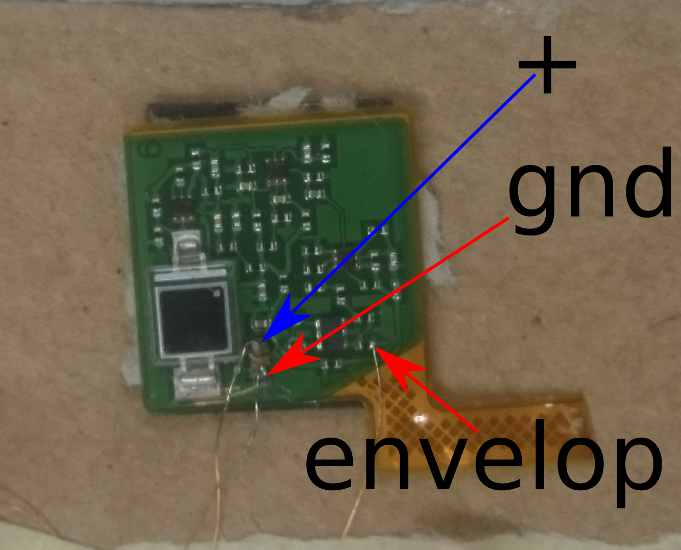
As you can see, connecting the sensors is quite difficult, because the contacts are tiny.
For measuring the pulse width, we wanted to use an Intel Edison, because we had one lying around. After hacking for a while and scanning the forums, it became apparant, that the interrupts on the Intel are in fact threaded and simply not fast enough for measuring 62us - 135us.
#include <iostream>
#include <vector>

#include <chrono>
#include <mraa.h>
#include <mraa/gpio.h>

using namespace std::chrono;

static volatile int 		counter_falling = 0, counter_rising = 0;
static  high_resolution_clock::time_point t1, t2;
static std::vector<microseconds> 	timeElapsed;
static bool 			valid;


// Interrupt routine for the input data from the TS3633 sensor
void IntrValveFalling(void* arg){
    counter_falling +=1;
}

// Interrupt routine for the input data from the TS3633 sensor
void IntrValveRising(void *arg){
    counter_rising += 1;
}

void IntrValveBoth(void *arg){
    if(valid){
	counter_falling++;
    	valid = false;
	t2 = high_resolution_clock::now();
	duration<double> d = duration<double>(t2-t1);
	microseconds us = duration_cast<microseconds>(d);
	timeElapsed.push_back(us.count());
    }else{
	counter_rising++;
	t1 = high_resolution_clock::now();
	valid = true;
    }
}


int main(int argc, char** argv){
    mraa_result_t rv;
    mraa_init();
    const char* board_name = mraa_get_platform_name();
    fprintf(stdout, "Version: %s\n Running on %s\n", mraa_get_version(), board_name);

    mraa_gpio_context m_gpio;
    gpio_edge_t edge_r = MRAA_GPIO_EDGE_RISING;
    gpio_edge_t edge_f = MRAA_GPIO_EDGE_FALLING;
    gpio_edge_t edge_b = MRAA_GPIO_EDGE_BOTH;

    // J17-7 on the Intel Edison Breakout Board
    m_gpio = mraa_gpio_init(6);
    if(m_gpio == NULL){
        std::cout << " cannot open J17-7 pin...\t closing" << std::endl;
    }

    mraa_gpio_dir(m_gpio, MRAA_GPIO_IN);

    rv = mraa_gpio_isr(m_gpio, edge_b , &IntrValveBoth, NULL);
    if(rv != MRAA_SUCCESS) std::cout << "MRRA return code: " << rv << std::endl;

    // J17-8 on the Intel Edison Breakout Board
    mraa_gpio_context m_gpio_2;
    m_gpio_2= mraa_gpio_init(7);
    if(m_gpio_2 == NULL){
        std::cout << " cannot open J17-7 pin...\t closing" << std::endl;
    }

    mraa_gpio_dir(m_gpio_2, MRAA_GPIO_IN);

    std::cout << "reading GPIO J17-7: " << mraa_gpio_read(m_gpio) << std::endl;
    std::cout << "reading GPIO J17-8: " << mraa_gpio_read(m_gpio_2) << std::endl;

    sleep(5);
    std::cout << "Counter falling= " << counter_falling << std::endl;
    std::cout << "Counter rising= " << counter_rising << std::endl;

    counter_rising = 0;
    for(auto e : timeElapsed){
	    std::cout << "counter: " << counter_rising << " E: " << e << std::endl;
	    counter_rising++;
    }

    mraa_gpio_isr_exit(m_gpio);
    mraa_gpio_close(m_gpio);

    mraa_gpio_isr_exit(m_gpio_2);
    mraa_gpio_close(m_gpio_2);
    mraa_deinit();
    return MRAA_SUCCESS;
}
There is a way via busy wait loops, which unfortunately can't be used when using multiple sensors. Here is the code:
#include <stdio.h>
#include <unistd.h>
#include <mraa.h>

int main() {
	 mraa_init();
	 mraa_gpio_context pin = mraa_gpio_init(...
Read more »
I'm pretty convinced at this point that the algorithm to use to find location is EPnP. The authors of the original paper have provided sample code to run the algorithm, which is awesome. But, the sample code depends on OpenCV libraries, so that's a bit of a hitch. I'll have to pull out or rewrite the parts of OpenCV that it uses in order to get this loaded on the Arduino Due.
So, here's the current plan:
1) Modify/ use the existing EPnP code while running on a desktop to derive the position and pose of the sensor board relative to the lighthouse. Values will be captured, and offline analysis will be done. i.e. This is not realtime, just proof that I can get the code to work.
2) Build a derivative EPnP library that does not rely on OpenCV. Ensure that it behaves the same as (1).
3) Load the code from (2) onto the Arduino Due, and have it calculate pose information realtime. Benchmark, and see if it's "good enough"
4) If the speed of the algorithm is (3) is too slow, iteratively attempt to optimize the algorithm, likely by trying to push as much math as possible into using integer math instead of floating point math. Not sure how easy it will be to do this with EPnP, but probably worth a shot.
5) Build support for on-device calibration of a world reference frame. I'm expecting this to have a user experience something like:
1) Place the tracked device where the origin should be & press a button. 2) Place the tracked device at least a meter away in the +Y direction & press a button. 3) Place the tracked device in the +X direction by about a meter & press a button.
At this point, the tracked object should be able to have a well defined world coordinate system, and it should know how that coordinate system maps to the Lighthouse's coordinate system. The Arduino should be able to consistently spit out the tracked object's location in the world coordinate system now.
And here's the part I really like: 6) It should spit out location data in standard NMEA sentences. That's the standard way that just about all GPS receivers report location information. Why does that matter? It means you could hook this up to any device that expects to use a GPS receiver, but instead it's using lighthouse tracking instead. For example, you could hook it up to a small drone using an off-the-shelf UAV board, and program flight paths using off-the-shelf software, without any modifications.
I've learned a lot in the last week about Kalman Filters, Discrete Linear Transformations, the Perspective-n-Point problem, and more. The big breakthrough was realizing that you can treat the lighthouse and its sensors as just a really high resolution camera that only sees a few points. And as a bonus, you don't have to deal with the usual computer vision problem of identifying "important" features of an image.
Perspective-n-Point is the problem of solving for the camera position and orientation given n points that the camera is able to see. This is effectively the problem we need to solve. (Technically, we want to know the position of the object relative to the camera, but that's a trivial difference.) There's been lots of research into the problem and a number of algorithms exist. The algorithms seem to fall in two categories: Iterative approaches that improve on an initial approximation, and algorithms that solve for the pose all at once. One of the most efficient strategies is an algorithm called EPnP, or Efficient PnP, which solves the problem in O(n) time. Once you have a good pose, if you can assume that the tracked object only moved a little between observations, it can be appropriate to use the previously calculated pose as the input to an iterative algorithm to get the new pose.
One concern is that the implementations of EPnP (and I suspect the other algorithms as well) work on floating point values, not integers. The Cortex M3 in the arduino Due does not have a floating point unit, and by at least one crude measure, floating point operations take ~40 times longer than integer operations. I'm doubtful that these algorithms would lend themselves to an integer variant of the solution.
And, just to throw a wrench into all of the above goodness, it's worth noting that the Lighthouse technology isn't quite the same as a camera. That's because the two sweeps of the lasers (to detect the horizontal and vertical angles) do not occur at exactly the same time. In fact, they're ~8ms apart. While a simple algorithm may ignore this, an algorithm targeting maximum precision would need to take it into account. For high precision, integrating the values from an inertial measurement unit (IMU) would also be a good idea (just like the Vive controllers and headset). To integrate all of these different measurement updates into a single pose, Kalman filtering appears to be the way to go.
So far the algorithm for deriving position from the lighthouse angles and known relative positions of the sensors is eluding me. I'm thinking that the solution will come from setting up a set of equations and then solving for the unknowns. And that's what I've been doing so far with pen and paper. Lots of trigonometry here, as I'm deriving all of my equations from trig relationships, setting up triangles wherever I can (they're everywhere!). At least it's a pretty awesome problem. I probably won't have much more time to work on it until the weekend. Just wanted to drop a note saying "I'm still working on it." More to come...
I haven't had as much time to work on this as I'd like. My daughter had a hip surgery a couple days ago, and she's and my other kids have been my focus lately. Anyway, the last time I was looking at this, I had some weird intermittent glitches that I was having a hard time tracking down. Given that the old code was basically taking the logic for a single sensor and running it six times (once for each sensor in the current setup), it wasn't really optimized and needed a major overhaul anyway. I spent a couple hours tonight to do that redesign and rewrite.
The first major change is that instead of having a separate ring buffer for each sensor, I now have a single ring buffer for all sensor data. This means that it's now obvious what order the sensors have been read. Previously, if processing lagged too much (usually because I was printing too much debug info to the serial port), it became impossible to keep the incoming sensor data in sync.
Since we now can easily tell what order the sensors have been read, I changed how the OOTC pulse is being read. Instead of each sensor separately detecting the OOTC pulse, it is now detected via cooperation of all sensors. This will be especially important in getting high precision angle measurements. While all sensors receive the signal at basically the same time and assert their lines together, the microcontroller has to service the interrupts serially, and hence they get timstamped separately. Now, when an OOTC pulse is detected, we look at all sensors to find which sensor's interrupt was processed first, as well as which sensor was processed first for deasserting the OOTC signal.
I also got rid of a little floating point math, which might speed things up a bit. I've also been able to verify that the ring buffer is being serviced frequently enough that there's no current risk of overflow.
I'm very happy to say that I'm now comfortable enough with the incoming data that I'm ready to start trying to triangulate position given the angles. But, this is my weakest area in this project, so it may take me a while to figure it out. If anybody has any pointers or references, I'd really like to hear them.
First off-- The code cleanup has gone well. Aside from being better structured, it now supports multiple sensors. Right now 6, but trivial to add more. Here's a short dump of the angles being captured:
The first thing to note is that sensors 0-4 appear rock solid. But, if you look closely at sensor 5, the X and Y values sometimes flip. Obviously not good.
I haven't root caused this yet. My initial thought was that it's due to the interrupts piling up for all six sensors when the initial sync pulse (a.k.a. OOTC) is sent. From the docs, it takes 12 clock cycles from an interrupt being asserted in hardware until the interrupt service routine (ISR) code starts up. No mention on how long it takes to return from the ISR, but certainly at least a few clock cycles. Let's assume that the entire ISR takes ~20 cycles to enter, run and exit-- it's a good ballpark figure. Then, if 6 interrupts are asserted at once (as happens when the OOTC pulse is sent), then the 6th interrupt will be serviced ~100 clock cycles later than the first interrupt. At 84MHz, that's ~1.2us. While that could be substantial for causing drift in the measured angles, it probably isn't enough to be causing the error above. (note: We'll fix the above issue by reading the OOTC pulse with only one sensor-- it's a lower priority for now, but will be necessary before we're done).
So, another interesting observation is that when this bug hits, X and Y are swapped. That's particularly odd because X and Y are acquired completely independently. It's hard to imagine an issue that would always affect both of them. This should be an interesting issue to root out.
Since I was able to get one sensor working really well, it was clear that the next step is multiple sensors. I've built a rig with 6 sensors. I'm not sure of all of the math yet, but I'm pretty sure that it is important to avoid more than 2 points being on a single line and more than 3 points existing on any plane.
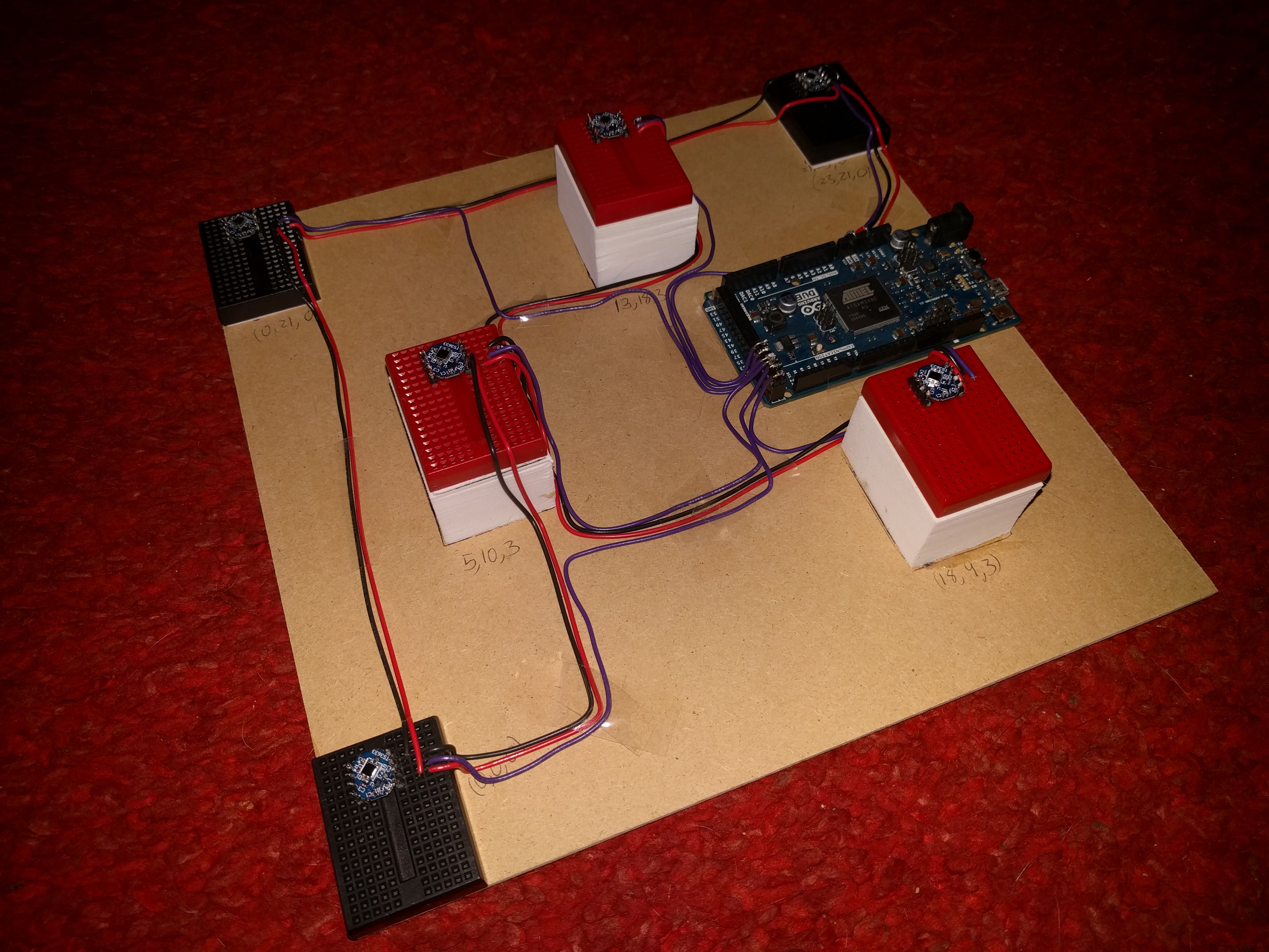
In expanding the code to support multiple sensors, I seem to have introduced a few bugs. Need to fix them before I can reliably get angular positions from all the sensors.
Create an account to leave a comment. Already have an account? Log In.
Hi Mike, did you see this?
http://hackaday.com/2016/11/30/where-is-my-drone-ask-lighthouse/
https://github.com/ashtuchkin/vive-diy-position-sensor
It's a very nice implementation of a dual LH base tracking with his own sensor cluster. Not full "pose" estimation but he gets <10mm position accuracy using a Teensy 3.2!
How is the project going?
I've about 4 things on the go at once at the min, I've managed to hack a hard drive and have a spinning mirror with a laser line scanning the room - just need to produce the split surface mirror to get a dual beam. I've put together some Verilog code for a lattice chip which does the timings and puts them in to a ring buffer, just need to do the SPI interface to pull them out of the buffer and transfer them so I know what size FPGA I need. I also have three versions of detectors laid out on a panelised PCB board waiting for the processor and FPGA panels to go on before sending them to be made.
Hmmm, at some point over the next couple of weeks I should finish one. Probs the Verilog will be easiest and let me finish the PCB too...
Lee
Hey Lee,
Work on my side has been fairly slow. Work and family have been eating up pretty much all of my time the last few weeks. That drone is pretty awesome, and a great example of the kinds of thing you can do with this kind of positioning. I'm being stubborn, though, and don't want to mandate the use of two lighthouses to determine position. One is enough, given sufficient math, and I'm bullheaded enough to keep going down that path until I get it working.
Sounds like you're making some awesome progress. Definitely post some pics of the scanning laser and the FPBA board when you have a chance, I'd be very interested to see what you've got going.
Hey guys, this project really caught my attention, it looks like you're both very dedicated!
For us readers who don't have a deep understanding of indoor positioning, could you briefly explain the difference between this approach and a more traditional SLAM technique?
Hey Alex,
As I understand SLAM, it's all about using computer vision to map out a space, and then using what the camera sees to determine where you are in a given space. And, since it's "Simultaneous," you're doing both at the same time. So, you're using the images and computer vision to determine where you are in a given space. Kinda like a person looking around a room and saying "looks like I'm in the middle of the family room."
This project, as well as Lee Cook's are more like a GPS system. Given the signals you receive, you can look at the precise timings of what you receive to calculate your current position. In both cases, you're looking for IR signals, and figuring out the time it takes for various sweeps of the lasers (and beacons in the case of Lighthouse) to strike your sensors.
Hi (again ;-) ),
I'm not sure how fixed you are on the Arduino Due (or if it was just a cheap platform you were looking at) but, after looking around, my first iteration at embedded processing is going to be with an Arm M4 system like the Teensy V3 (96Mhz, single floating point unit and, supposedly, DSP extensions for maths processing).
I was going to try and get a vanilla version working on a Teensy and then, if that's not good enough, either switch to a Pi Zero or start optimising using the DSP extensions depending on how far off it is....
Lee
Lee, thanks for the continued feedback-- I really appreciate it. I'm not overly tied to the Due, it's more that I looked through the range of boards for what could give me the best sampling precision, and another factor was also what I have lying around. The things that I really like about the Due are low cost, high pin count, and the ability for each pin to fire a different interrupt has been handy. I am, however, very concerned about the lack of floating point hardware. I haven't nailed down the algorithm yet, but it looks like it will be floating-point intensive.
An earlier effort by Trammell Hudson (https://trmm.net/Lighthouse) into lighthouse interfacing also used a Teensy, so that definitely seems like a positive direction. I really like its small size.
I figure that worst case, one could use an Arduino Due for capturing the data points, then feed them to a Pi to do the math. I'm *assuming* that the Pi wouldn't be well suited to the extremely timing critical work of capturing the signals, given that it's running a general purpose OS. But the Pi would be awesome for doing the math-- I'm sure you could run OpenCV on it, which could save a lot of effort.
Right now, my main focus is on getting an implementation of a perspective-n-point algorithm to derive position of the sensors relative to the Lighthouse, and that work is going on mainly on a desktop PC. Once I've got that figure out, the next step is getting it to work on small, cheap hardware.
No problem. Never sure how much to comment before it comes across as interfering. I remember being really surprised that the Teensy had the FPU and the DSP extensions. It was this project made me look in to it:
https://hackaday.io/project/5809-biopotential-signal-library
I’m trying to make sense of the raw measurement info you gave me against the software model I’m putting together. Does the lighthouse system sweep the lasers at different rates? Sweeping the vertical at half the rate because it’s only sweeping 90deg vs the 180 of the horizontal?
Don't worry about interfering-- the whole reason I have this posted here is to get interference (comments/ questions/ suggestions/ etc.) from others. The Teensy seems like a powerful little board. I think it's likely I'll end up using one. (I especially like the small size; I can easily see it fitting on a small indoor drone :-)
The lighthouse sweeps both lasers at 60 rotations per second, and precedes each with a strobe. The length of the strobe encodes three bits of information, including whether the successive sweep will be X or Y.
I updated the spreadsheet I sent earlier by adding another page that derives the angles of each sensor relative to the base station. Hopefully it will be more obvious by looking at it. If not, please let me know and I'd be happy to explain more. Like I said earlier, I've gotten pretty into this project and enjoy discussing it.
You have the same as I had, where the angles essentially define a square.
But if the board was flat on a desk (i.e. the 3cm was a vertical difference) with the base 1m above and 3m away then it would be on an angle of around 18 degrees wrt to the base.
Given the perspective, the vertical angles should be around half of the horizontal?
I got these from my model:
BASE 1 (x:0.0, y:3.0, z:1.0)
Sens: (Az Angle, El Angle), Approx Relative Power, VISIBLE?
0: (-1.5937, -17.6153), 0.164, YES
1: (-2.4896, -19.1790), 0.180, YES
2: (-0.4897, -18.3468), 0.172, YES
3: (1.6935, -19.1790), 0.181, YES
4: (1.0486, -17.8898), 0.167, YES
5: (1.5681, -17.8517), 0.166, YES
The angles themselves arn't that important, but the relative ones should match. The only reason I can think is that they're running the vertical axis at half the rate of the horizontal - but halfing the sweep. It kind of makes sense for the added accuracy, and should be possible to interleave with the others if it is exactly half the rate.
The issue may be that I didn't have everything lined up very well when I took those measurements. I was not methodical about the position at all. I just took another data set with the sensor plate placed 305 cm horizontal, 119 cm vertical displacement. Also, the way I'm measuring the angles, I'm considering the laser sweep to go from angle 0 to angle 180. It looks like you're considering it to go from -90 to +90. But I agree, the delta is what really matters.
New angle measurements:
0:(86.502,111.332) 1:(89.633,111.999) 2:(88.724,110.971) 3:(89.605,110.798) 4:(87.445,110.564) 5:(85.809,110.891)
P.S. In gathering this sample, in order to get the base plate perfectly perpendicular to the base station, I rotated it so that the horizontal sweep times for sensor 1 and 3 were the same (or as close as possible). I did see that when I attempted to get them identical, I do get a significant increase in jitter for those samples of up to .03 degrees. This is because the Due has to complete one ISR before it can start the next, and when they're aligned well, it's not deterministic which will fire first. It wouldn't happen with an FPGA, but then again, that would cost more, too. I'm hoping that the PnP algorithm will be robust enough to account for the occasional scenario when two sensors happen to line up like this.
I did a reasonable amount of VHDL about 7 years ago for a system I was working on, so I know the princilples and language, but I wasn't involved in the synthesising etc - it would definately need some effort.
Mike, those sensors are excellent! If you have the lasers (or even a BoM and circuit) which pair with these sensors I'd be very interested. It would short-cut my idea:
https://hackaday.io/project/14977-room-based-vr-positioning
to the point where it would come of the shelf.
Hey Lee, they are pretty awesome sensors. Easy to use and awesome precision. Are you familiar with the HTC Vive VR system? That's where all of this technology is coming from. Some really smart guys at Valve came up with the lighthouse design, which I believe was inspired by the VOR navigation system. The lighthouses I'm using are the production versions used with the Vive, and can be bought separately. (There's a link the "Components" section above.) If you're not familiar with how the lighthouses work, here's a good link and video that describe it:
I thought I had seen a teardown that listed laser part numbers at one point, but I can't seem to find one that does now. Valve, who designed this technology, are licensing this royalty free. The fact that they're making the TS3633 and TS3633-CM1 available are a good indication that they're serious about this commitment. I believe they're holding off on opening up the lighthouse to other manufacturers right now because they don't want to fragment the market with competing but non-interoperable solutions (think VHS vs. Betamax).
Yeh, I've been following VR for a while, especially since Oculus came on the scene.
Lighthouse is very cool but the tech isn't something that hackers could put together, which means you have to buy thier base station system. It's also patented so anyone trying to put together a copy would need permission - definately no open source developement for gaming systems which compete. The one I've suggested could be used anywhere for anything and is, relatively, simple to implement in hardware.
I'm a firm believer that it's open platforms that make markets grow, and open interfaces that stop the development headaches of multiple systems.
A large company like Microsoft should should take the lead here and expand on the VR HID class to produce put together some standard usage tables to use as a reference. At the minute it's like early graphics cards, game designers are going to be implementing for specific hardware - it's taken till now for Vulkan to (hopefully) sort it out.
I definitely appreciate open platforms and interfaces. I'm optimistic that we'll see that with the lighthouse technology, too. The biggest reason is that the lighthouse technology (as well as most of the technology in the HTC Vive) was not designed (& hence patented) by HTC. Instead, its origins are all Valve. And whereas HTC has the financial motivations to keep the tech closed and proprietary, Valve's motivations are very different. They benefit the most if the VR gaming landscape explodes. As a massive video game distributor, they'd want people to have a very positive and easy experience with VR and buy more games. From what they've said in the past, they'll be freely licensing it all. I sincerely hope they keep to that.
Dude, one sensor? That's really accurate. You probably need 5 for 6-DOF tracking, but for simple position 1 would likely work.
Hey Duane, I'm only using one sensor right now just to get the algorithms sorted out. The Due should be more than capable of handling a bunch more sensors. Definitely agree with minimum 5 sensors needed for 6DOF. Might be able to get away with fewer if the tracked object is a robot driving on the floor (i.e. always the same height/ constrained to a plane). I've got a lot of studying up to do on the algorithms to derive position...
Become a member to follow this project and never miss any updates
 Timescale
 staticdet5
 Luke Beno
 minifig404
Hi, When I place 3 sensors in a flat position, I have a lot of noise. I think is something physically, reflections, light... How can I fix it?