 Dan Levine
-
1Step 1
http://website.palette.io.s3-website-us-east-1.amazonaws.com/instructions.html
Instructions
Let's make Pallette!
This guide will enable you to create the Pallette Tongue Controller using our design files. We explain each step, so that developing Pallette is straightforward.
Pallette has three parts:
1. An embedded sensor ribbon
![]() 2. A water-tight enclosure
2. A water-tight enclosure![]()
3. Firmware and software
![]()
The Sensor Ribbon reads and understands your tongue movements using infrared and software, and the device fits in your mouth via a mouthguard and enclosure.
With this guide, you will mold the physical form to your mouth, embed and seal the sensor circuit within the form, and program the device to complete the Pallette device. Each section begins with a list of materials you need, and outlines the steps required to complete assembly.
Approximate Cost: $200+
Time Required: 1-3 weeks
-
2Step 2
http://website.palette.io.s3-website-us-east-1.amazonaws.com/materials.html
Materials
Before jumping in we'll need to make sure you're prepared. The table below details the different components you'll need to make Pallette. Each item links to where you can obtain it. We left checkboxes so you can keep a checklist of what you have.
*You will need to install the CC Debugger driver and the Bluegiga SDK on a Windows computer or virtual machine, in order to program the Pallette Sensor Ribbon.
Pallette PCBs
PCB manufacturing takes time, so it's better to order the PCBs first. Send the Pallette fabrication zip file inside the hardware design files folder to a PCB manufacturer to receive the Pallette PCBs. You can get a quote here with your desired quantity and turn time. With the fabrication information in the design file, you will get 0.014 inch FR-370HR boards with gold immersion finish, white soldermask, black silkscreen and v-scores, which will be quite pricey (~$100 each for 10 boards and 5-day turn time).
![]()
![]()
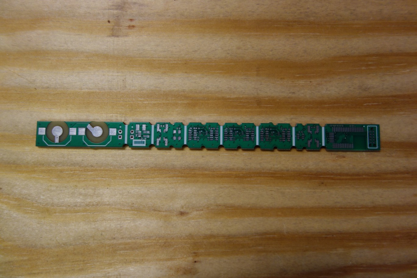
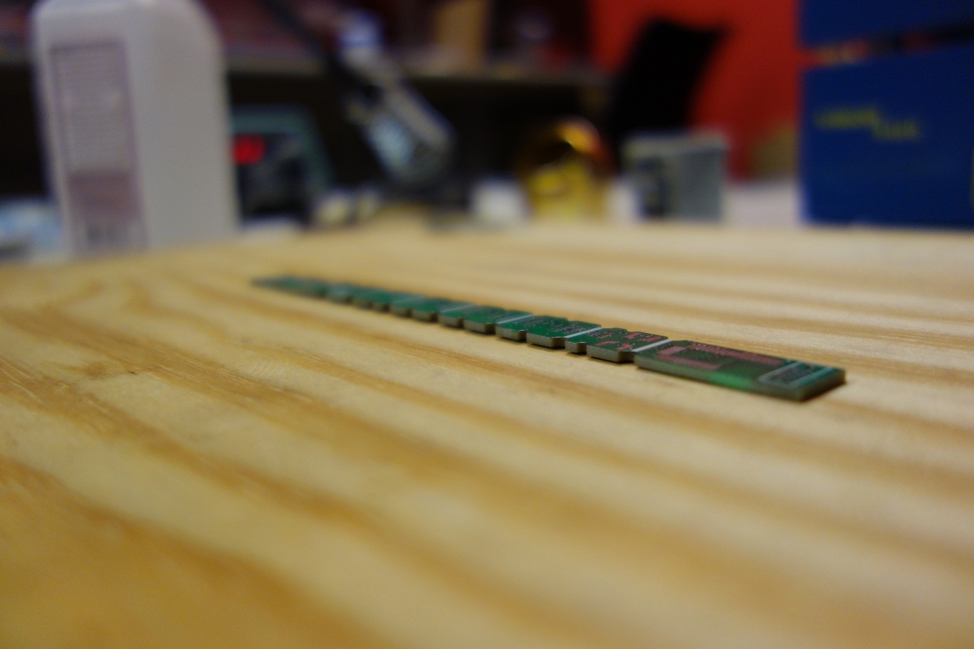
Alternatively, you can get the boards for $33 each with this special deal. However the boards will be 4x thick (FR-4 0.062" material) with lead-free solder finish, green soldermask and white silkscreen. (Photos below feature an older design)
![]()
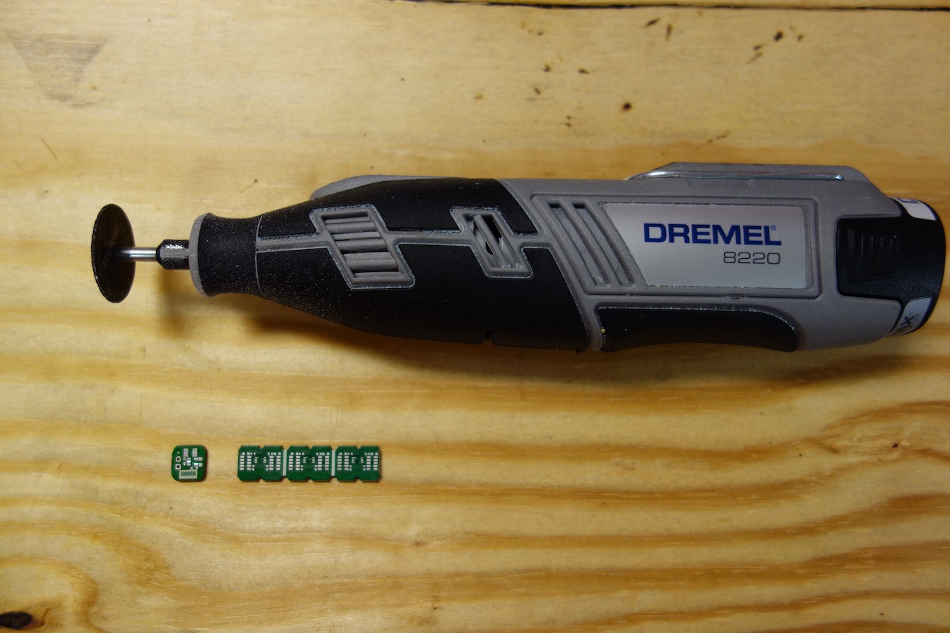
They won't come with v-scores, so you'll have to cut the boards along the thick white lines with a Dremel.![]()
![]()
PCB Assembly
To get PCBs assembled, you can either send the PCBs and fabrication zip file to a PCB assembler, or reflow solder the PCBs yourself. The PCB assembler charges the cost based on the quantity of your order, component cost and turn time. (You can get a quote here.) The approximate labour cost for assemble 10 boards at 5-day turn time is around $150 per board; component cost is <$30 per board. On the other hand, if you want to do reflow soldering yourself, you will need to buy electronic components and additional tools:Additional materials for reflow soldering Electronic Components*
RoHS Compliant Solder Paste
RoHS Compliant Flux
Electronic Hot Plate Preheating Station or Hot Air Soldering Rework Station
Tweezers*This is a Digi-Key cart for 10 boards worth of components. To see the Bill of Materials for one board, click here.
Step 5 will explain how to do reflow soldering in detail. But while you wait for the PCBs to arrive from the manufacturer, you can start making a Pallette device by following the next step - fitting a mouthguard.
-
3Step 3
http://website.palette.io.s3-website-us-east-1.amazonaws.com/mouthguard.html
Mouthguard
What you will need Sisu Mouthguard
Fork Bowl
Hot water
MirrorTo begin assembling Pallette, you'll need to obtain the form of your top teeth. We'll use the mouthguard to both fit your teeth and to capture their form. We specifically use Sisu, because the holes on the mouthguard will enable us to mount the Pallette Sensor Ribbon (Step 9).
You can see Sisu's official fitting instructions here, or watch the video below.
Once you have fitted your mouthguard, we can proceed to the next step, where you will make a clay mold of your teeth which will help to form the Pallette device. -
4Step 4
http://website.palette.io.s3-website-us-east-1.amazonaws.com/imprint.html
Imprint
What you will need Molded Mouthguard (from Step 3)
Air-Dry Clay
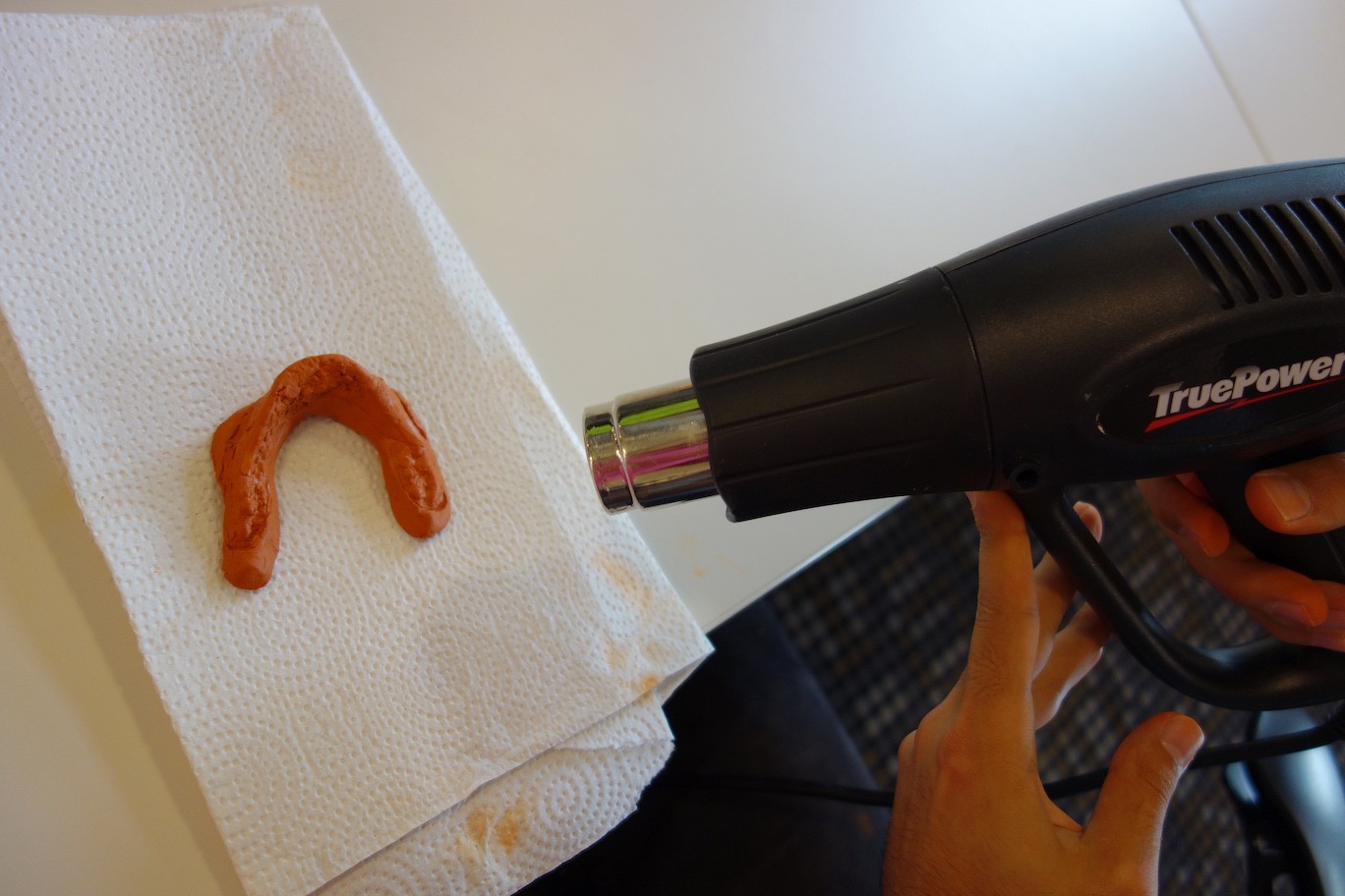
Medium Power Heat GunWith the molded mouthguard from Step 3, we'll make a clay imprint of your top teeth. This clay imprint will be used to determine the positions of the circuit boards on the top teeth (Step 6), and help with sealing the assembled Sensor Ribbon (Step 8).
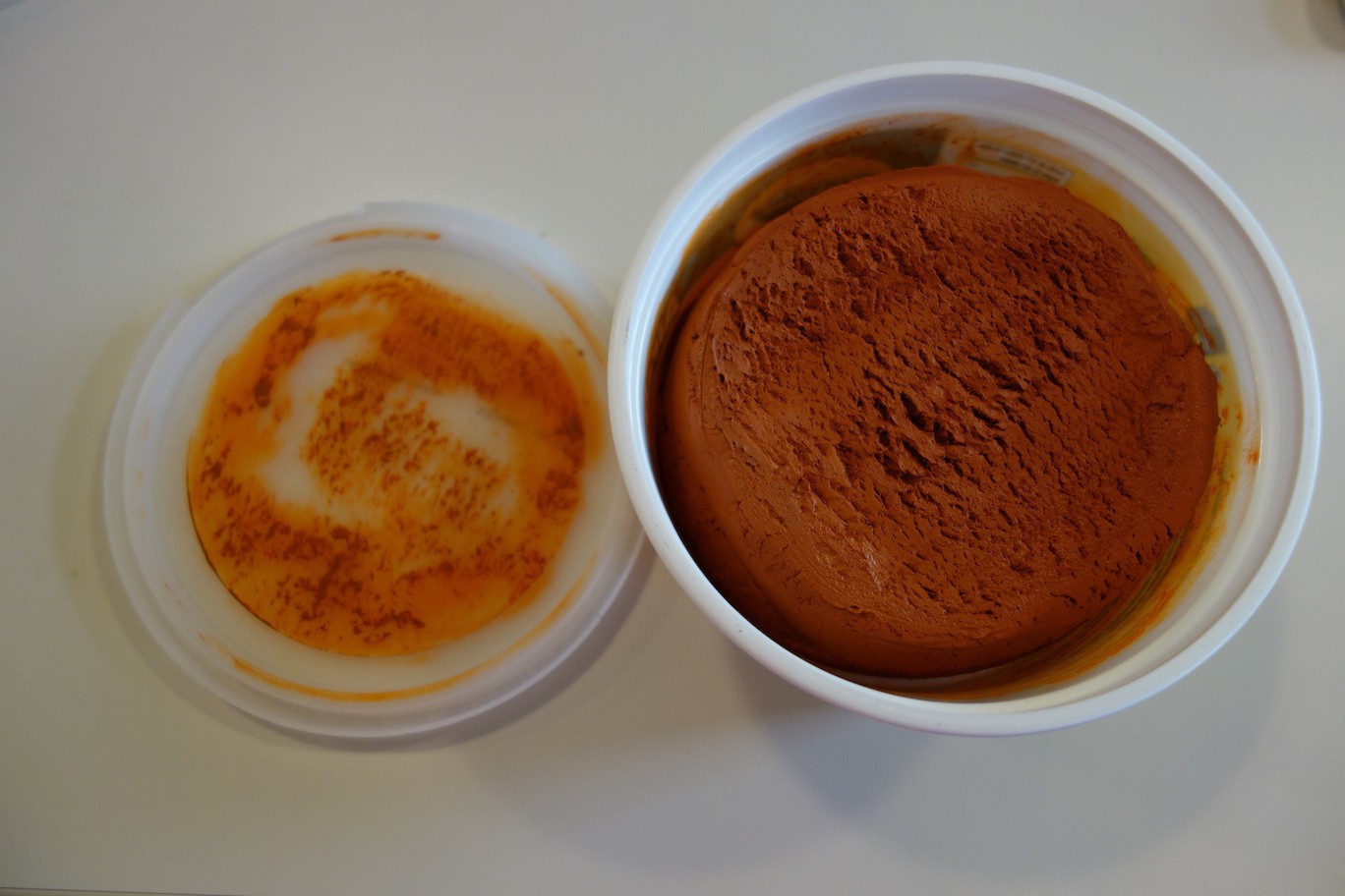
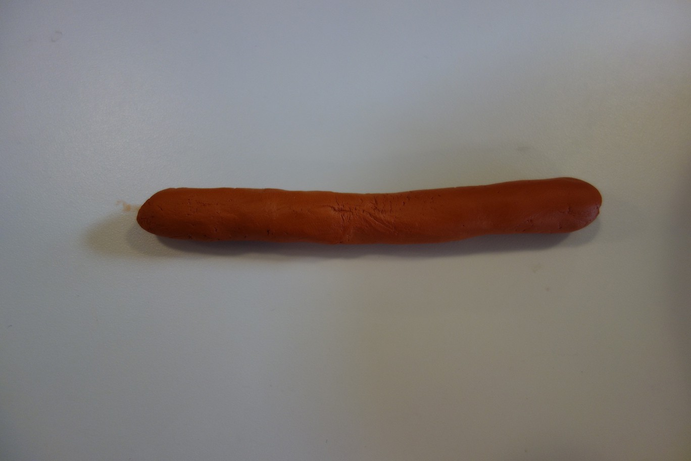
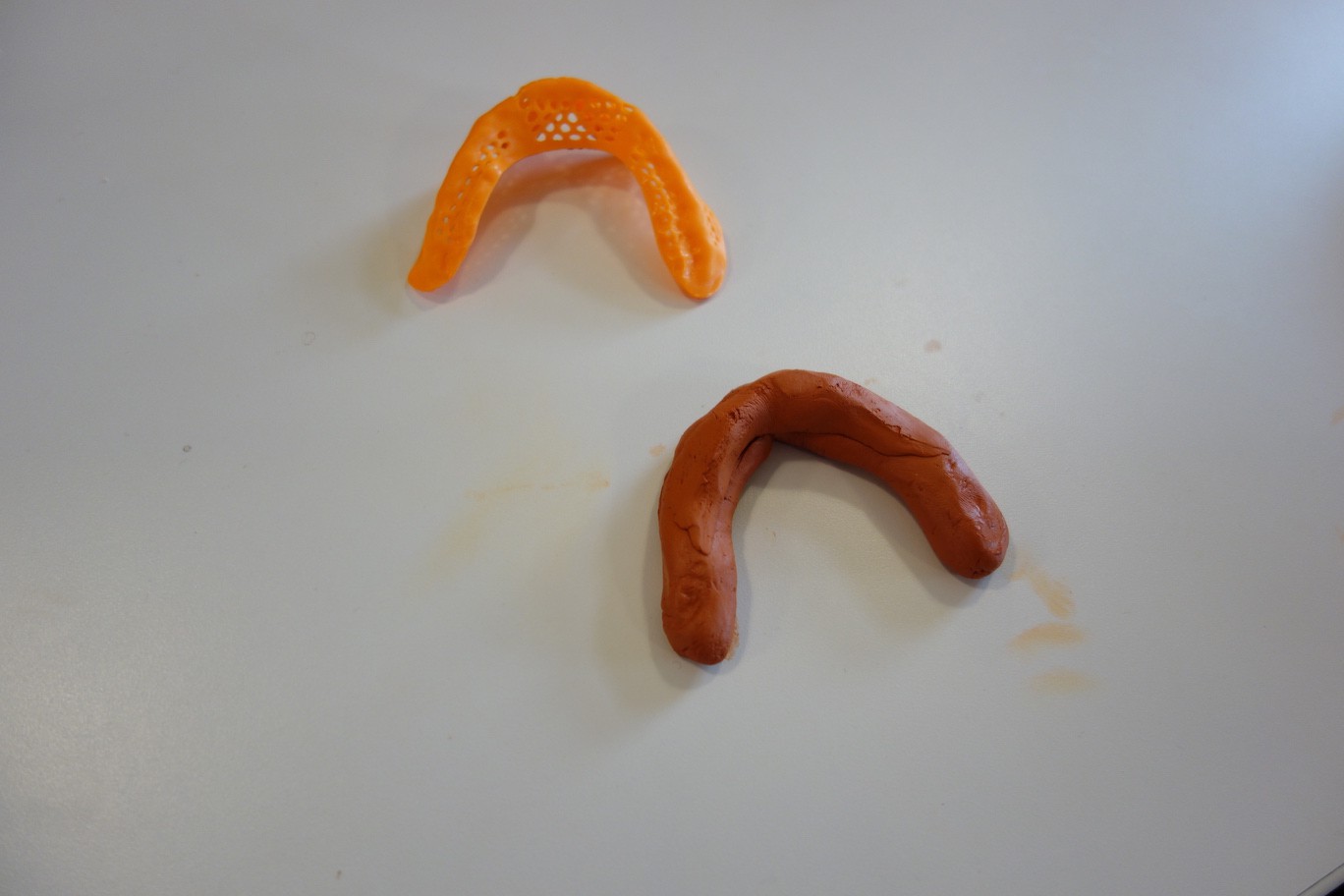
Start by breaking out the air-dry modeling clay. Beware the clay stains.
![]()
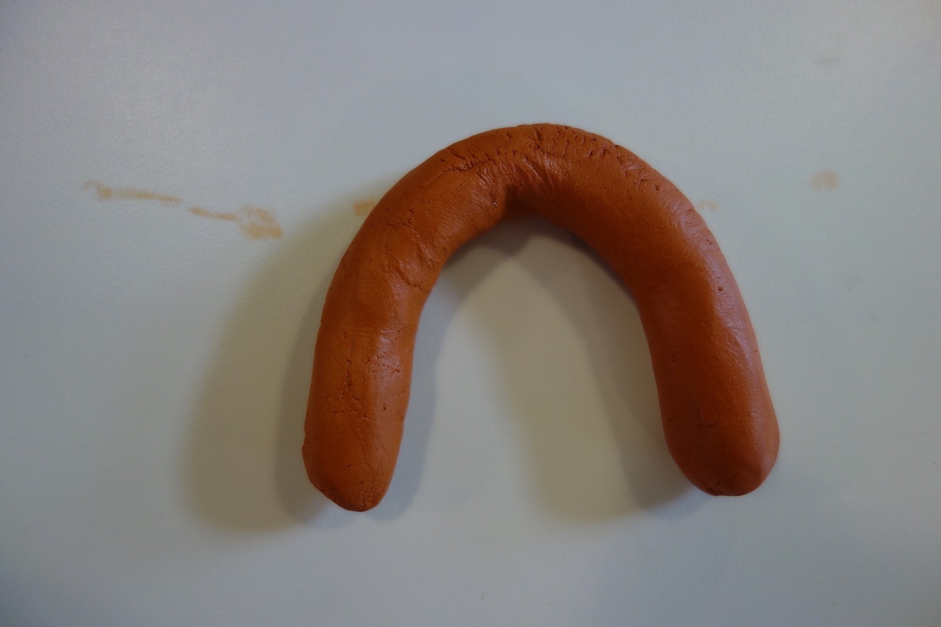
Roll it into a snake, roughly 1 inch thick. Form an arc with this snake underneath your mouthguard, leaving roughly 1/2 inch at the ends.
![]()
![]()
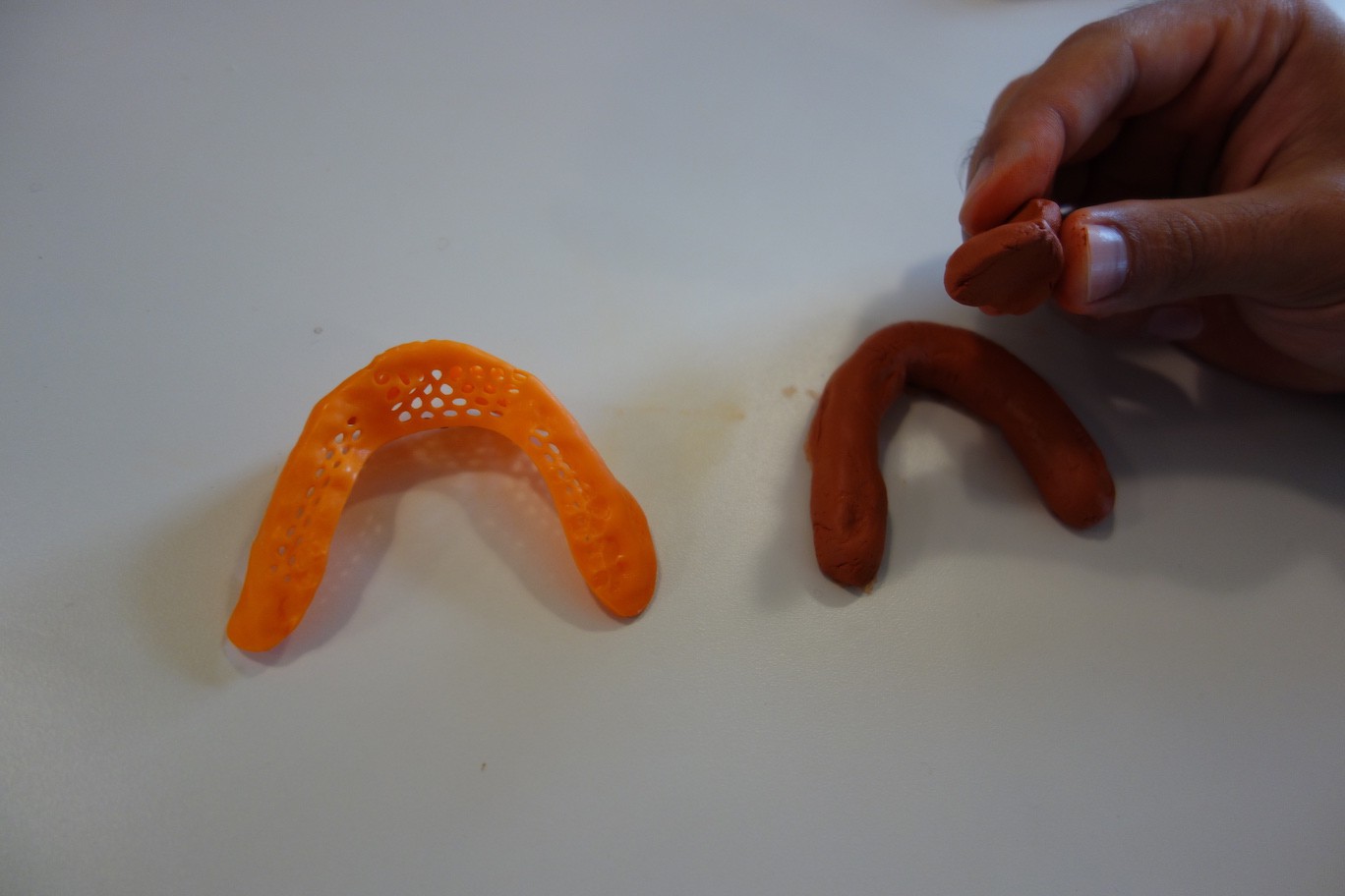
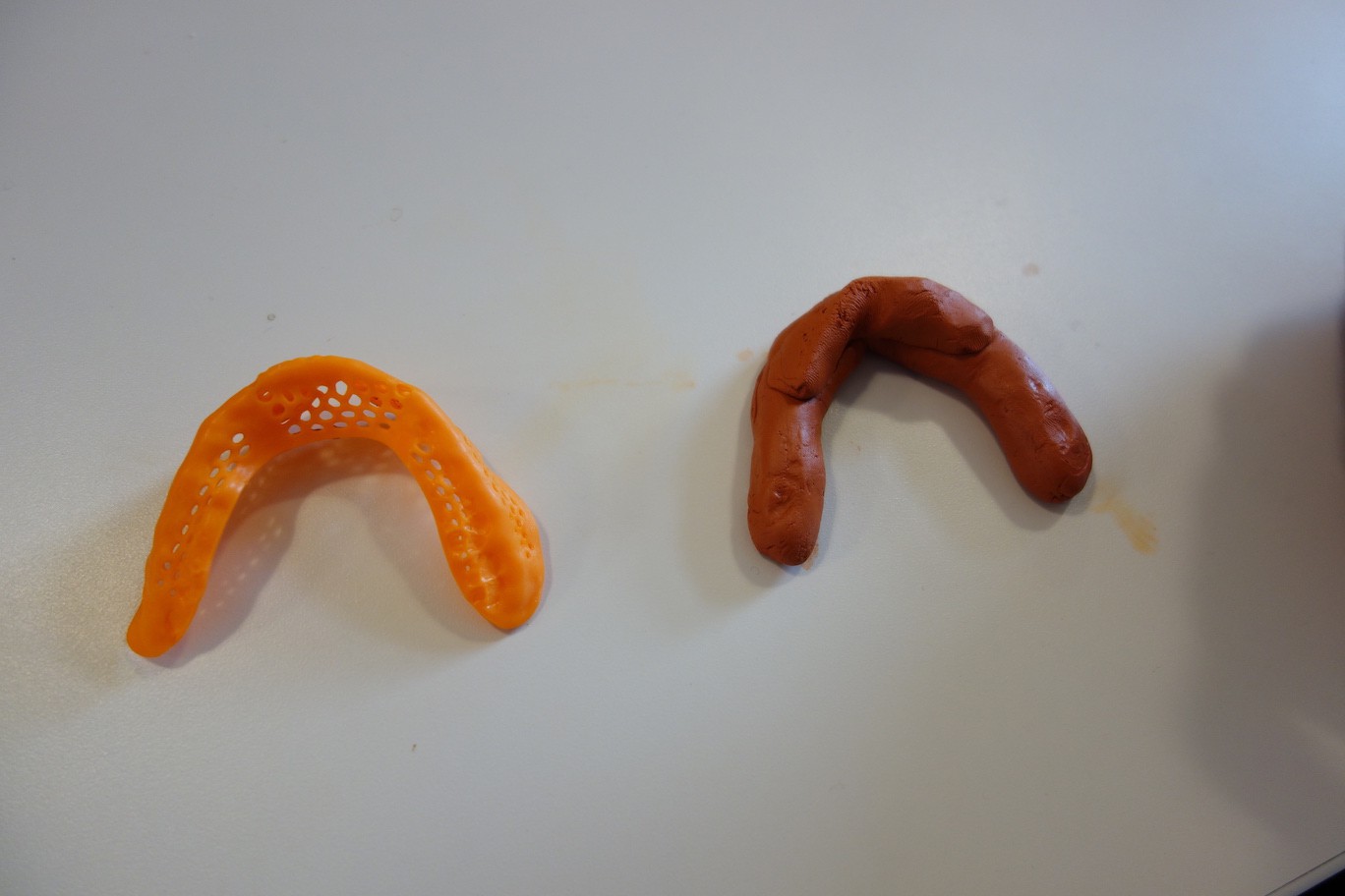
Add a bit more clay to the middle of the snake to match the height of the middle part of the mouthguard.
![]()
![]()
![]()
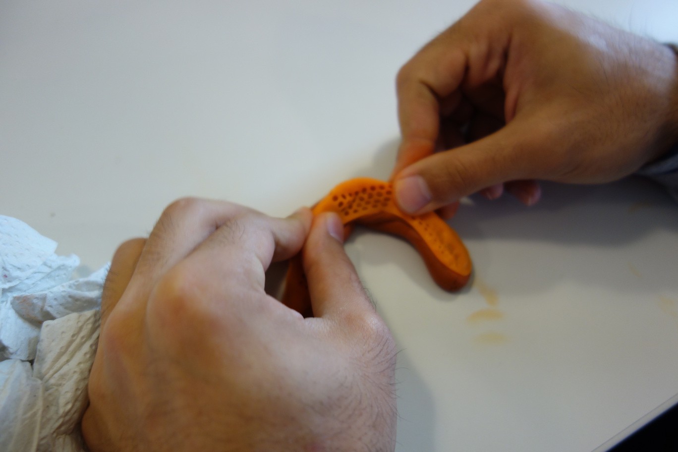
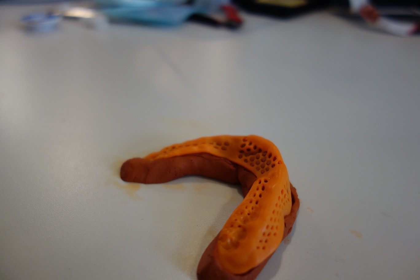
Place the mouthguard on top of the clay. Gently press down to form the teeth imprint. Check if the clay fills the entirety of the mouthguard, add or remove clay accordingly.![]()
![]()
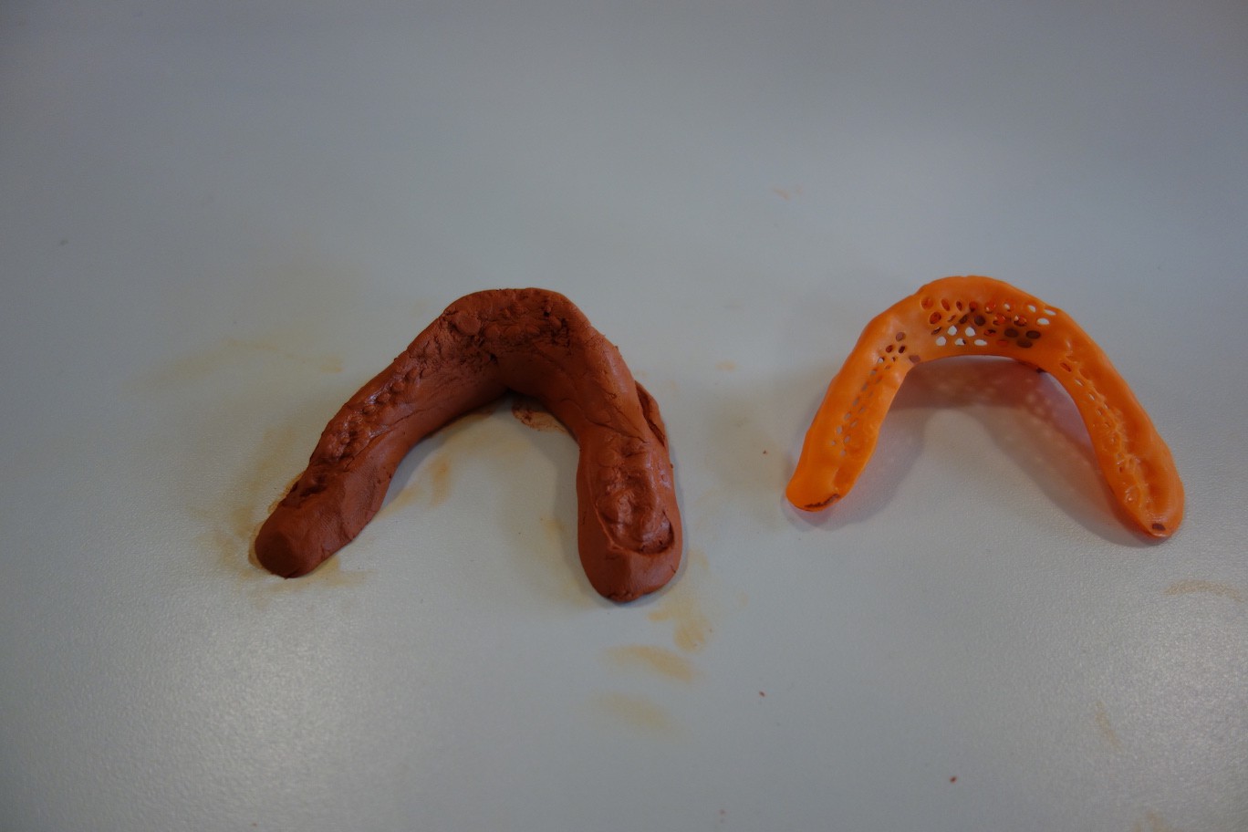
Gently lift up the mouthguard, make sure the clay imprint stays in shape.![]()
To harden the clay imprint, heat it up with a heat gun under low heat for approximately 5 minutes. The imprint will turn whiter when it hardens.
![]()
Teeth imprint complete! You'll use this clay mold to align the Pallette circuit boards and to ensure that the final Pallette device fits properly. -
5Step 5
http://website.palette.io.s3-website-us-east-1.amazonaws.com/reflow.html
Reflow Soldering
If you have the PCBs assembled by an external PCB assembler, you can skip this step and go straight ahead to the next step. But if you want to reflow solder the Pallette PCBs youself, please follow the instructions below.
What you will need Electronic Components
RoHS Compliant Solder Paste
RoHS Compliant Flux
Electronic Hot Plate Preheating Station or Hot Air Soldering Rework Station
Tweezers
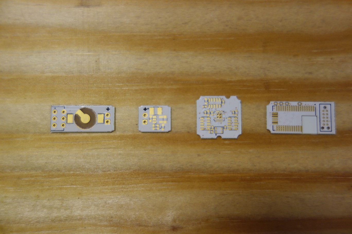
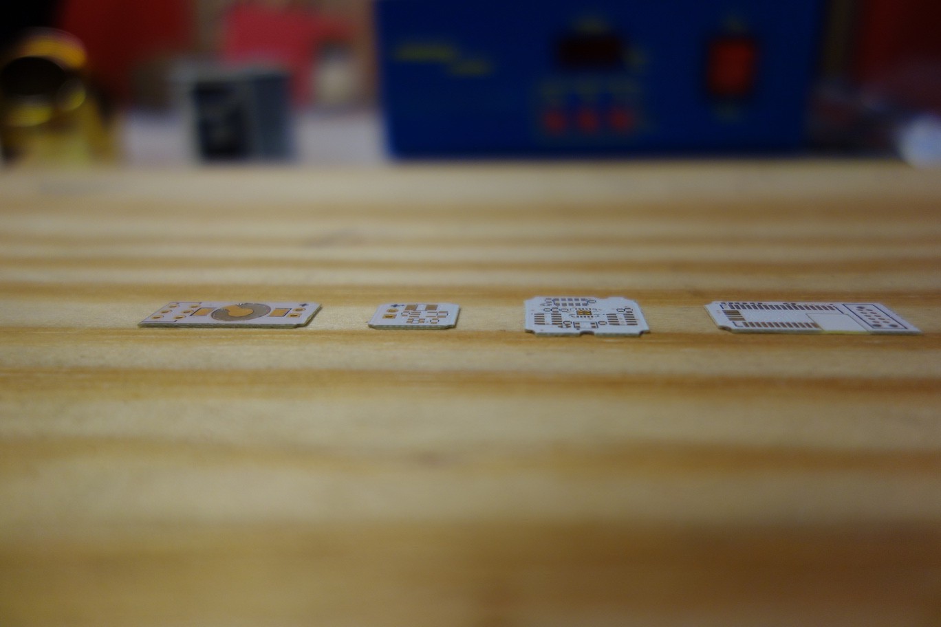
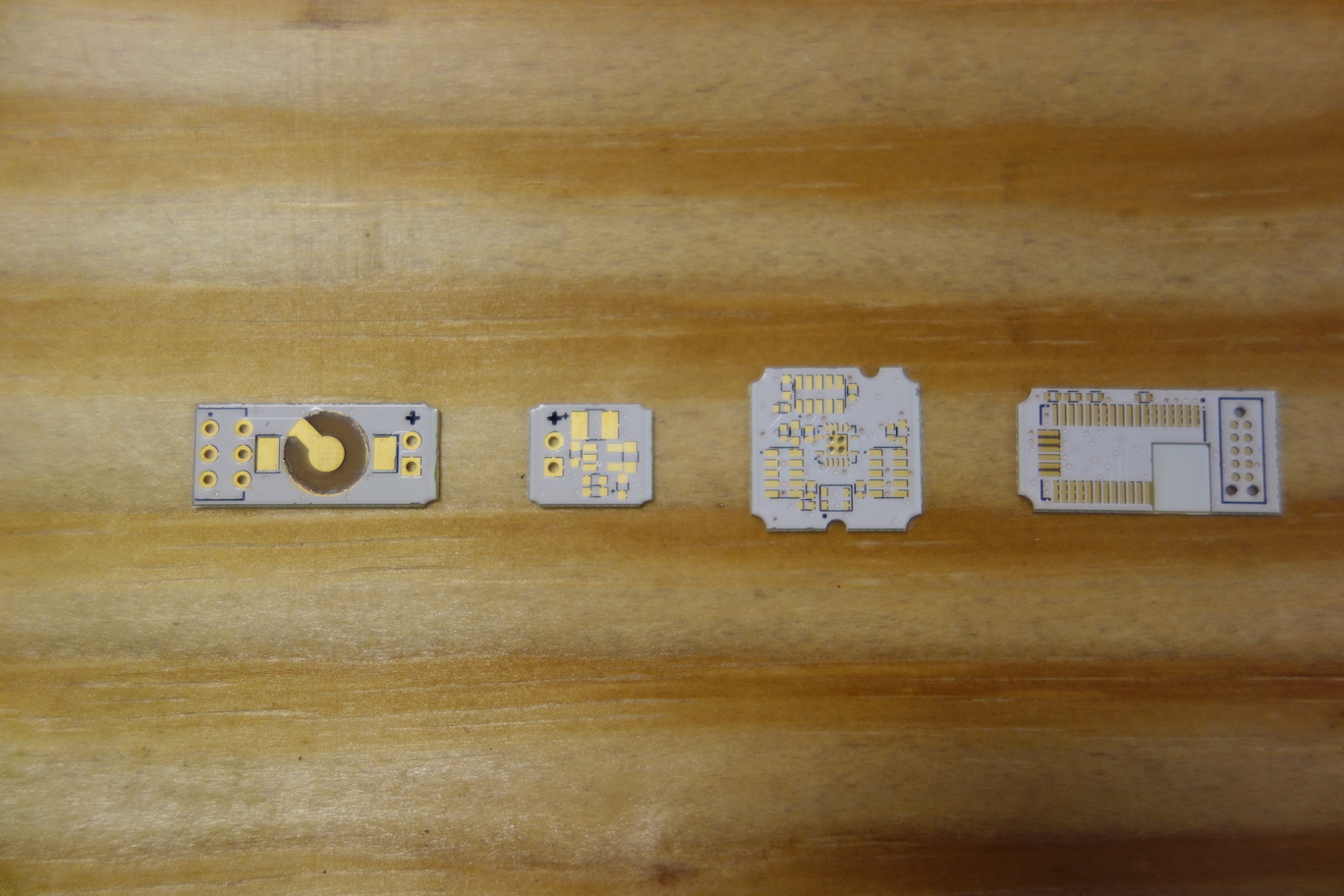
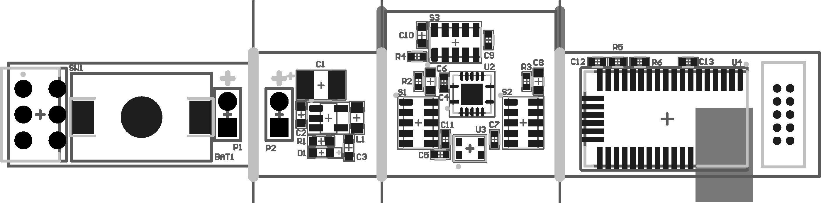
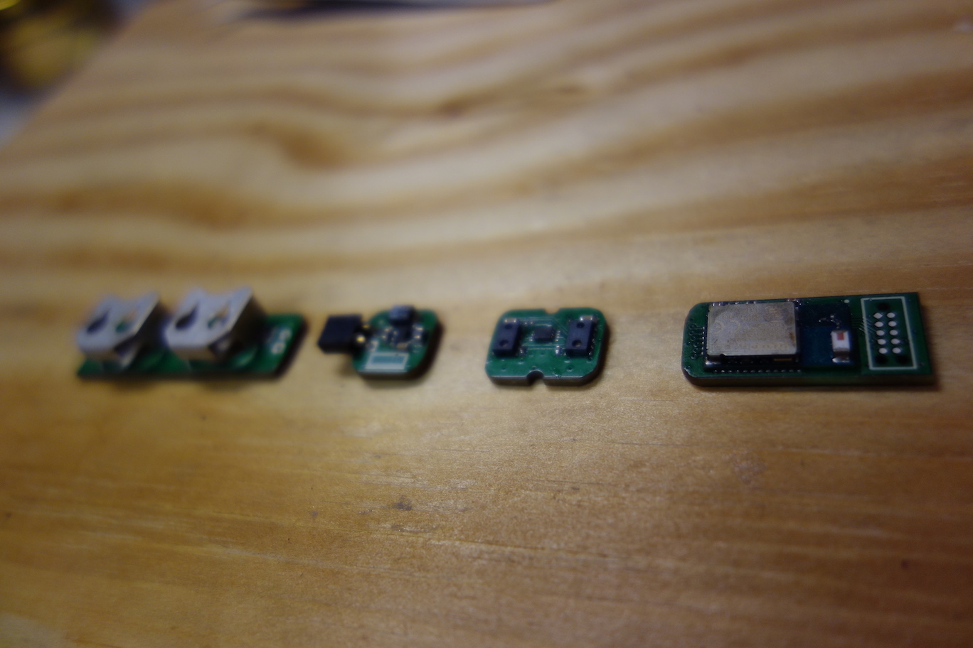
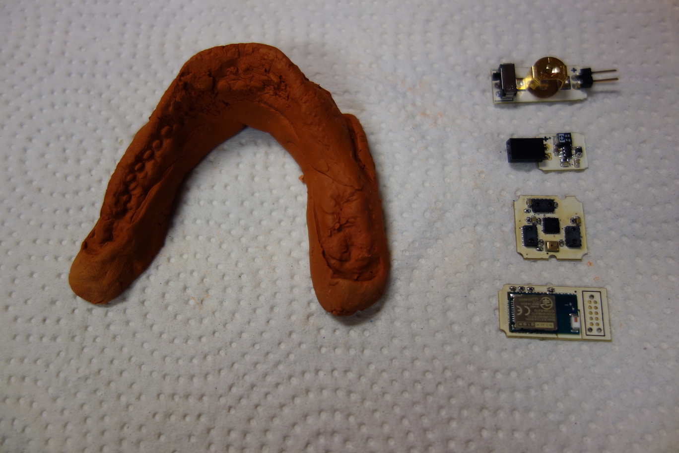
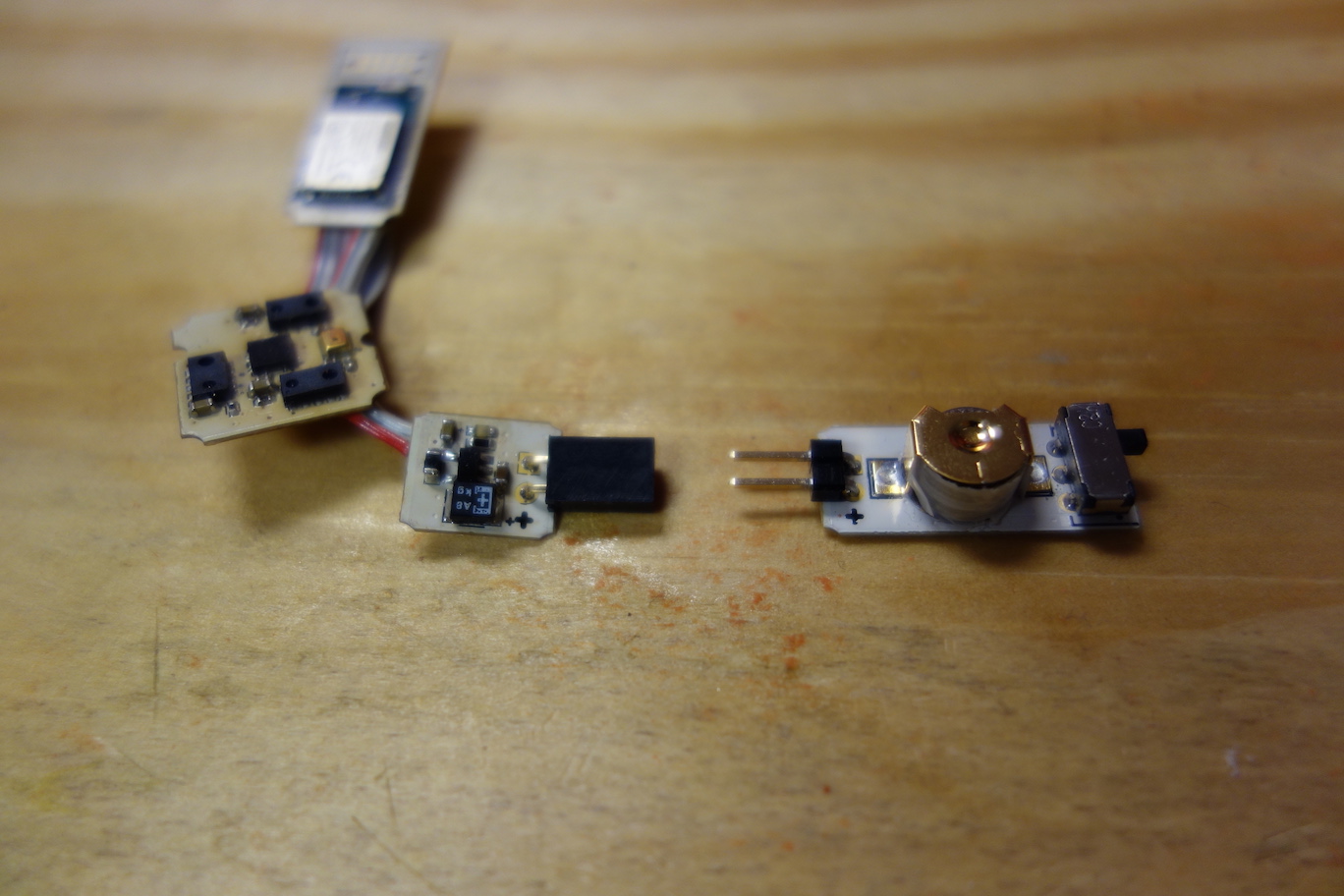
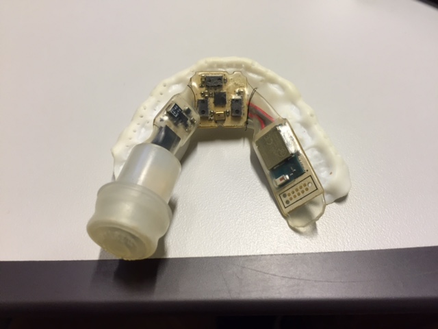
Pallette PCBsA complete Pallette circuitry consists of four boards (as shown in the photo below, from left to right): a Battery Board, a Voltage Regulator Board, a Sensor Board, and a Microcontroller Board.
![]()
The photos below show you the process of reflow solder the Voltage Regulator Board.
![]()
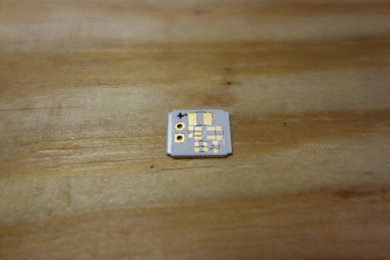
First apply solder paste on the solder pads.
![]()
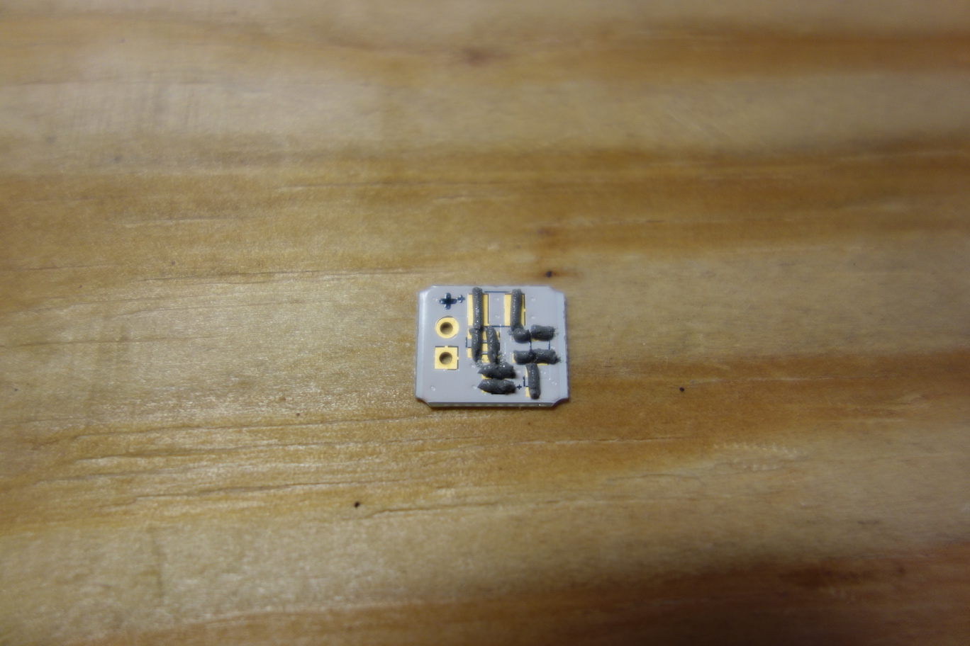
Next, place components on their designated locations. Make sure the polarities of the tantalum polymer capacitor and the LED are correct. The '+' symbol on one side of the footprint indicates anode.
![]()
Turn on the hot plate, set the temperature to 210°C (410°F). When the temperature of the hotplate reaches 210°C, use tweezers to place the PCB to the center of the hotplate, wait until the solder paste melts completely (when the solder paste is shinning), then carefully remove the PCB from the hotplate using tweezers.
![]()
The video below lets you catch a glimpse of reflow soldering of the Pallette PCBs.
You can also watch the tutorial videos below to learn reflow soldering. For more resources, please go here.
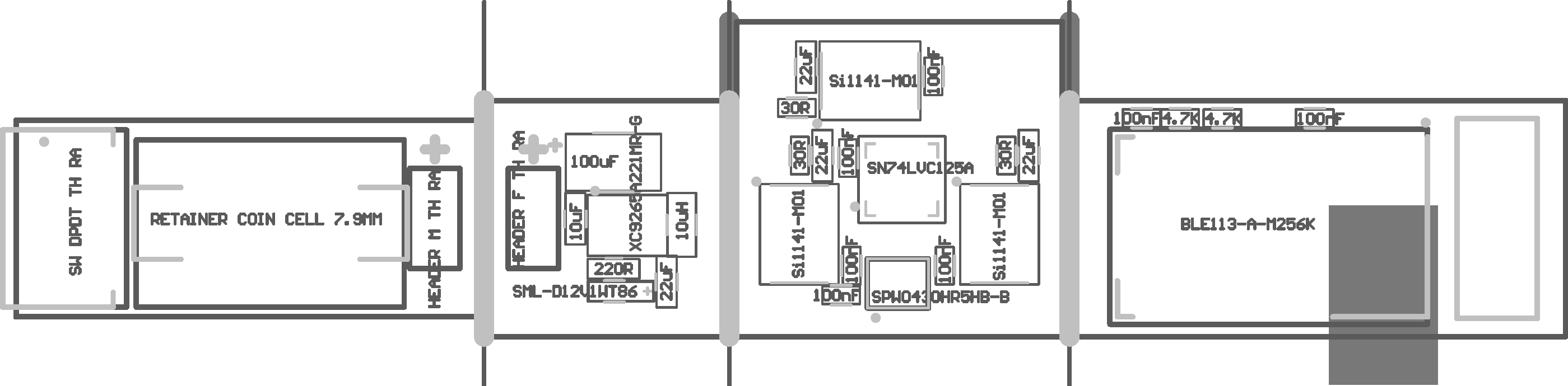
The component placement of the four boards is shown below.
![]()
![]()
You can find more Pallette hardware schematics and drawings here. Once you finished soldering, your boards should look like this.
- The Battery Board
![]()
- The Voltage Regulator Board
![]()
- The Sensor Board
![]()
- The Microcontroller Board
![]()
Next, we will solder wires to the back of the boards to connect the boards together.
- The Battery Board
-
6Step 6
http://website.palette.io.s3-website-us-east-1.amazonaws.com/ribbon.html
PCB Ribbon
What you will need Soldering Iron
Soldering Iron Tip
RoHS Compliant Solder
Desoldering Wick
Wire Stripper
Wire Cutter
Tweezers
Ribbon Cable 0.05" Pitch
Multimeter
Energizer 376 Cell Battery
Assembled PCBs from Step 5 or PCB assembler
Clay Imprint from Step 4
Adhesive Tape
Fine Tip MarkerNow you should have PCBs as shown below:
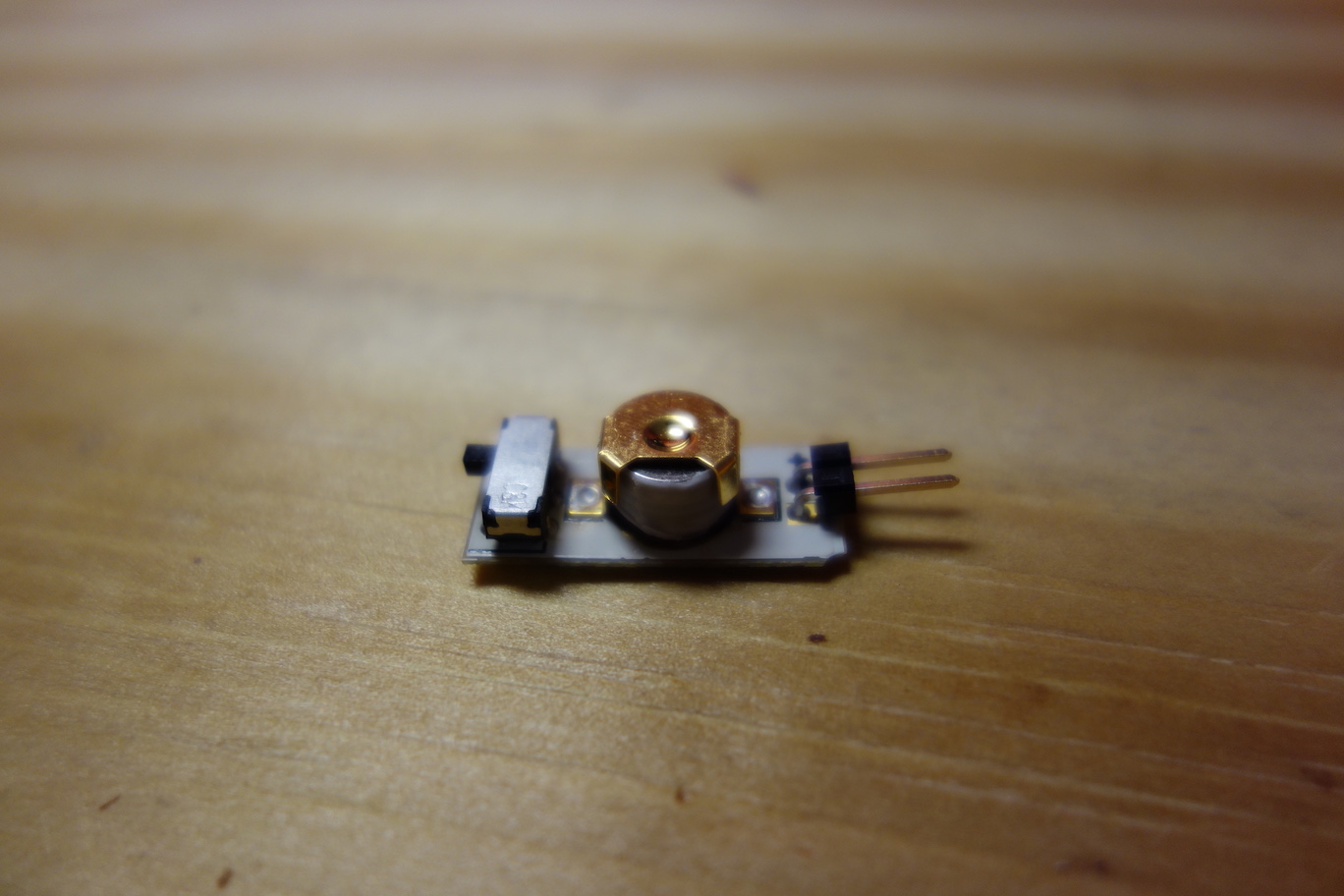
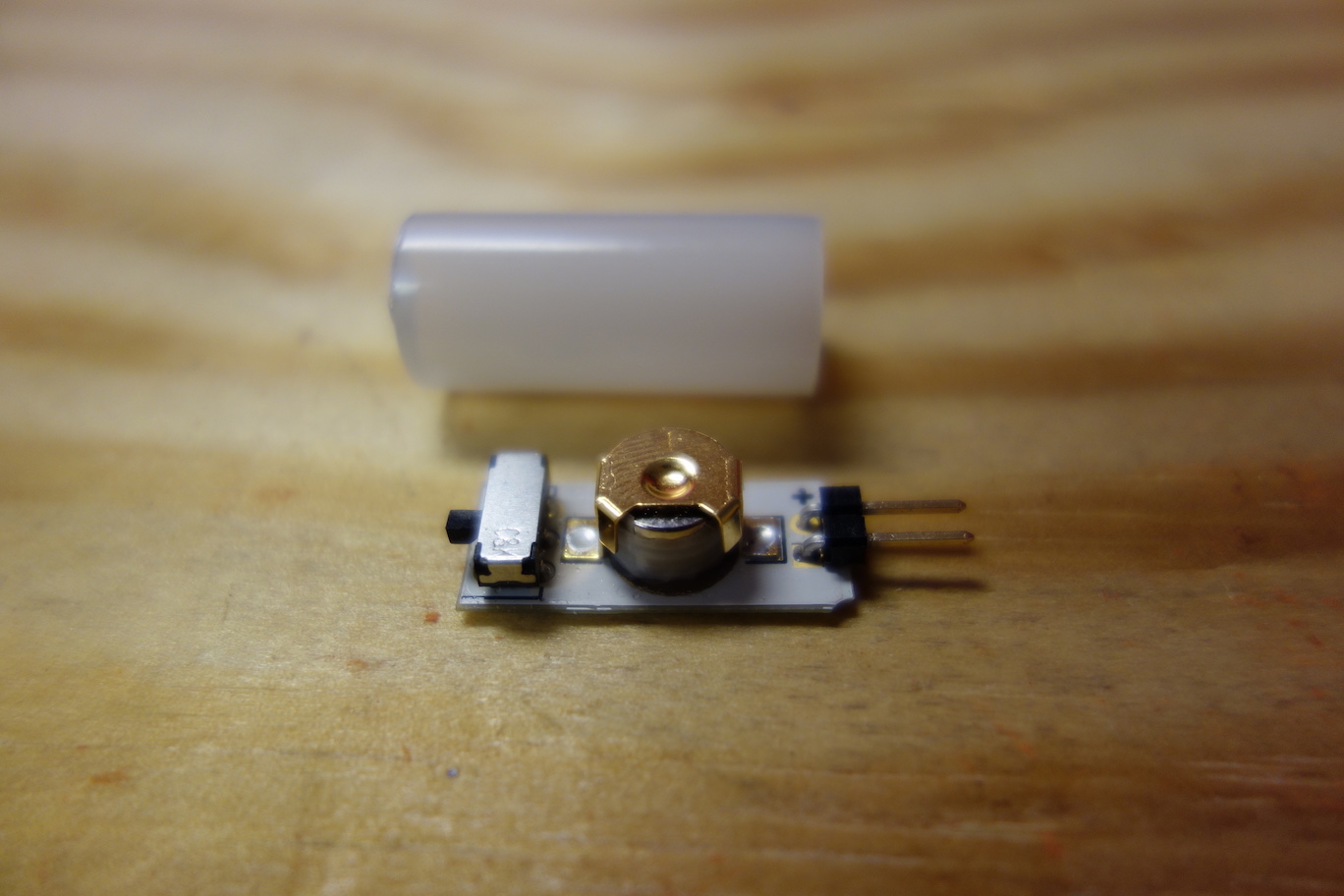
- The Battery Board
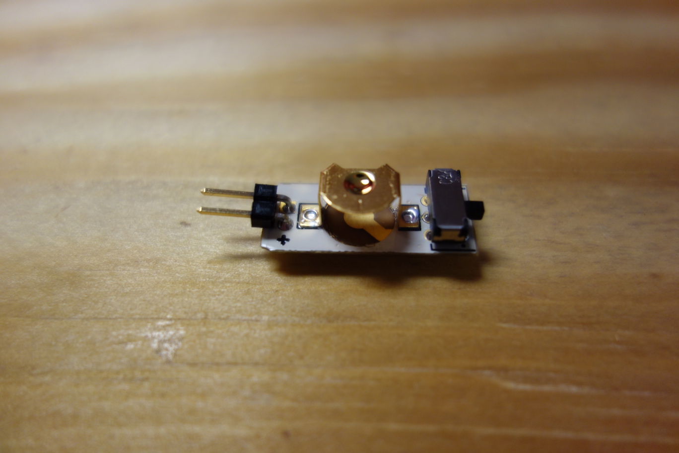
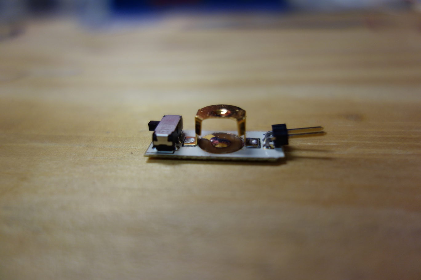
![]() The Battery Board consists of an on/off switch, a battery holder for two 376/377 cell batteries, and a male header to connect to the Voltage Regulator Board. This board outputs a voltage of 3.1V if the batteries are new. The Pallette circuit will continue to function until the battery voltage drops below 2.2V.
The Battery Board consists of an on/off switch, a battery holder for two 376/377 cell batteries, and a male header to connect to the Voltage Regulator Board. This board outputs a voltage of 3.1V if the batteries are new. The Pallette circuit will continue to function until the battery voltage drops below 2.2V. - The Voltage Regulator Board
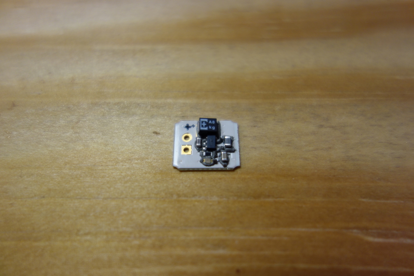
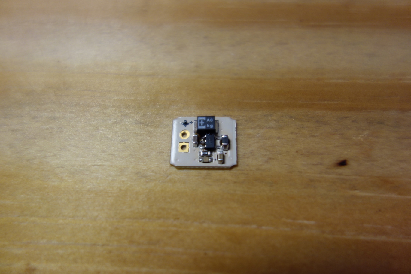
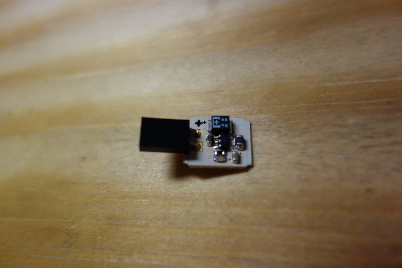
![]() The Voltage Regulator Board converts the voltage from the Battery Board to 2.2V. It automatically maintains this voltage level to protect sensitive electronic components and ensure consistent sensor readings.
The Voltage Regulator Board converts the voltage from the Battery Board to 2.2V. It automatically maintains this voltage level to protect sensitive electronic components and ensure consistent sensor readings. - The Sensor Board
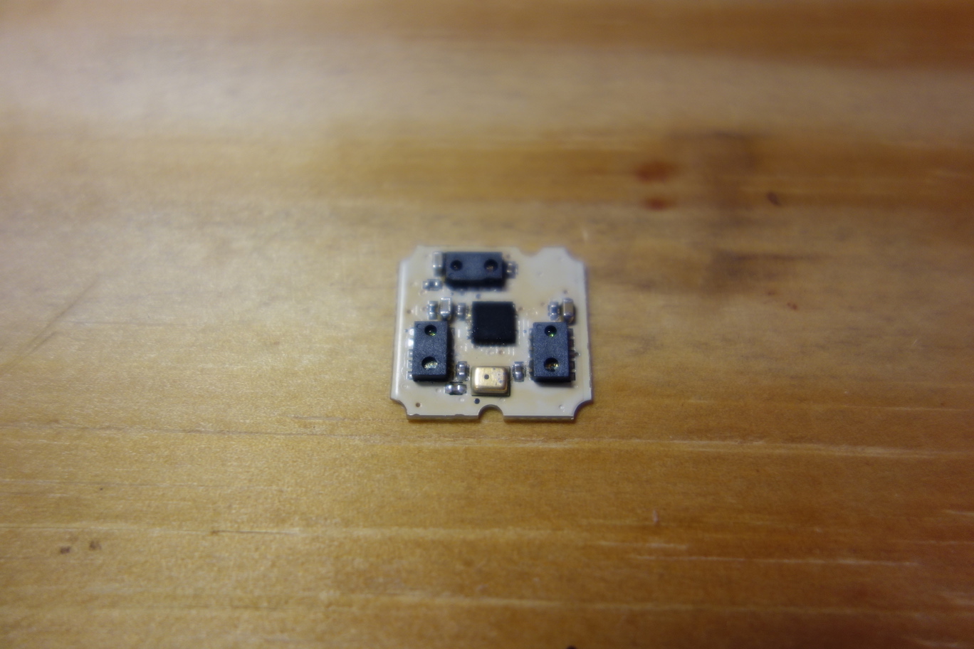
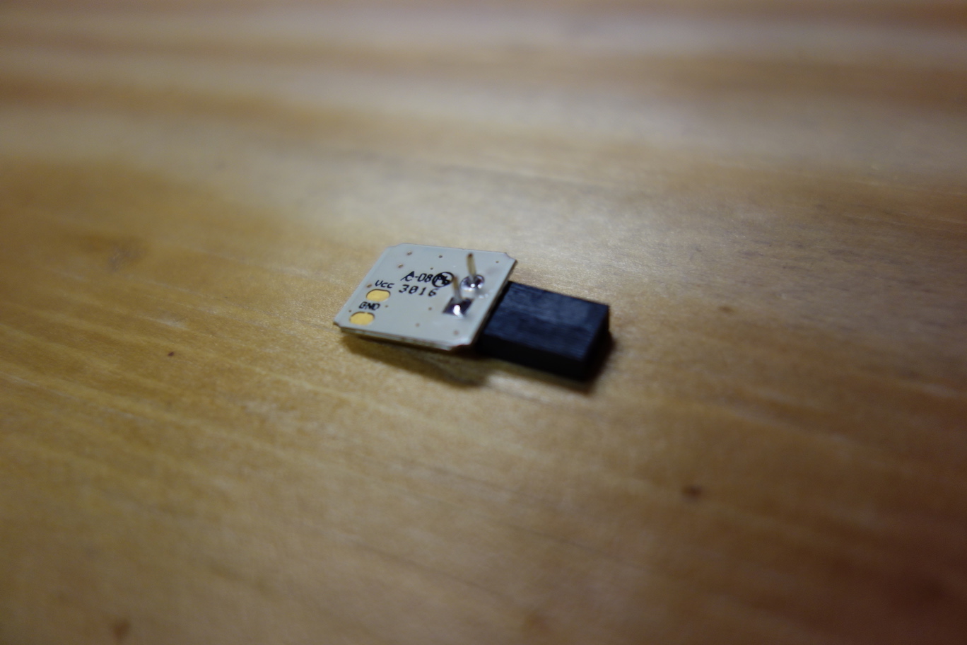
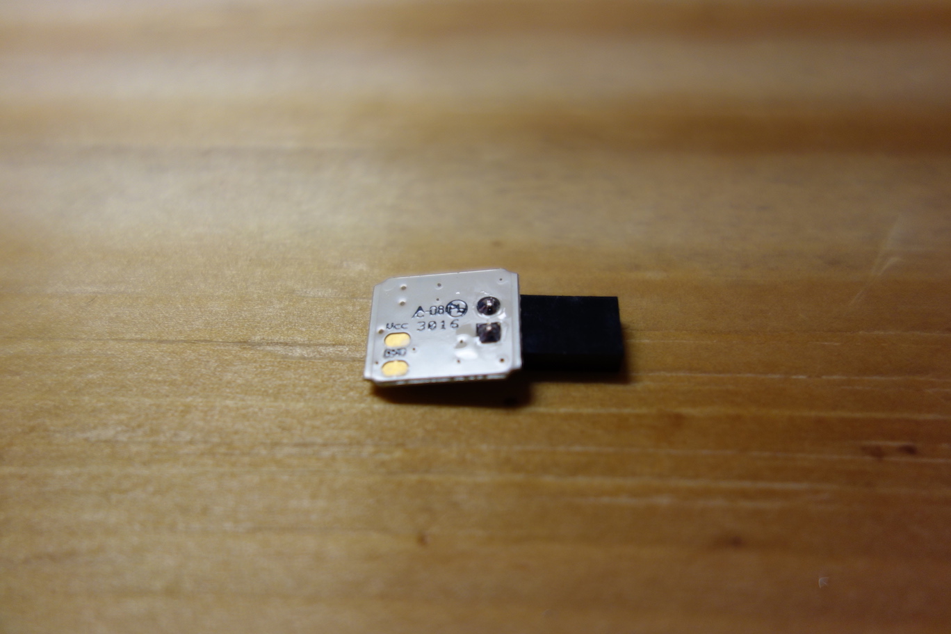
![]() The Sensor Board has three infrared sensors, which are strategically positioned to track tongue movement accurately. It also has a golden microphone chip which detects tongue tapping, in order to register a selection.
The Sensor Board has three infrared sensors, which are strategically positioned to track tongue movement accurately. It also has a golden microphone chip which detects tongue tapping, in order to register a selection. - The Microcontroller Board
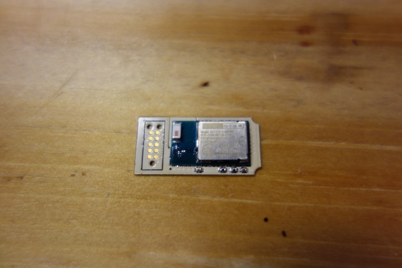
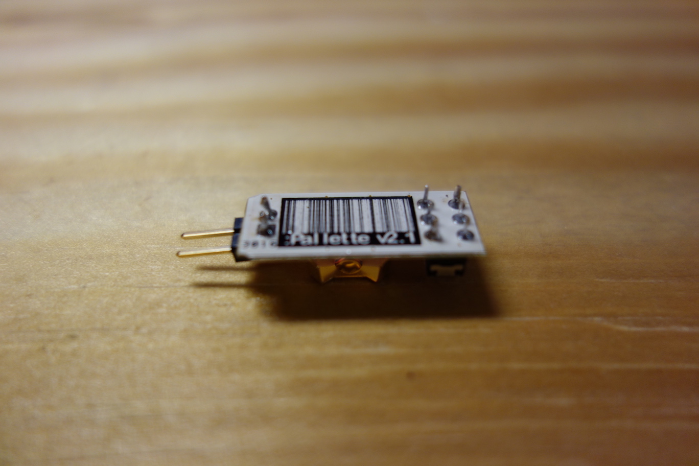
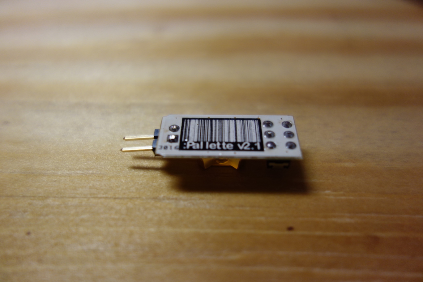
![]() The Microcontroller Board consists of a Bluetooth enabled Bluegiga BLE113 microcontroller and an in-circuit programming footprint. The microcontroller enables Pallette to wirelessly communicate with a computer or a mobile device. The programming footprint allows developers to program the microcontroller, either with our firmware, or their own firmware.
The Microcontroller Board consists of a Bluetooth enabled Bluegiga BLE113 microcontroller and an in-circuit programming footprint. The microcontroller enables Pallette to wirelessly communicate with a computer or a mobile device. The programming footprint allows developers to program the microcontroller, either with our firmware, or their own firmware.
If you ordered the 0.062" green PCBs, they will look like this (photo features an older design):
Trim the leads![]()
First, we need to trim the leads of the connectors with a cutter, so the leads won't poke holes on the heatshrink when we seal the electronics in Step 8. Cut off the full length of the exposed leads, leaving only the solder joints with a smooth surface.
![]()
![]()
![]()
![]()
Next, we better test the boards individually before we connect them together.
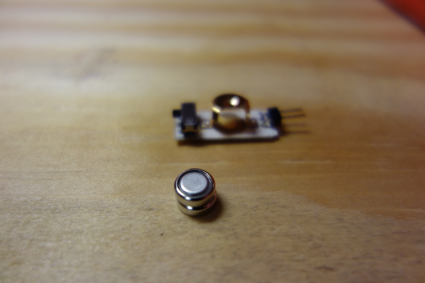
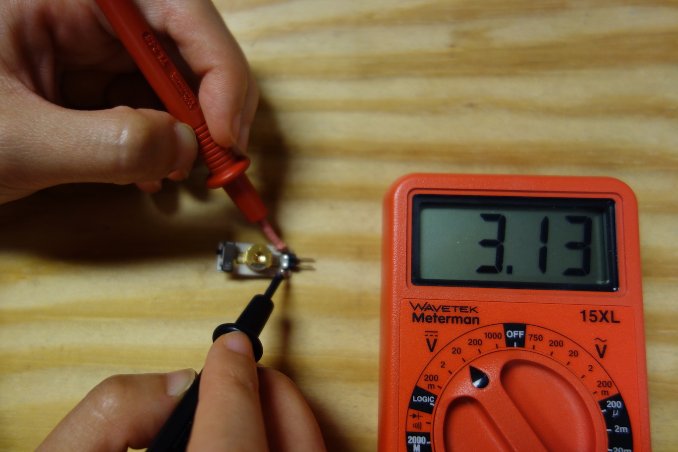
Test the Battery BoardYou need two Energizer 376 cell batteries and a multimeter.
![]()
Stack two batteries and tape their side together.
![]()
Push the batteries inside the battery holder, positive side (flat side) up.
![]()
If the batteries are too loose in the battery holder, add a bit of solder to the central round pad under the battery holder.
![]()
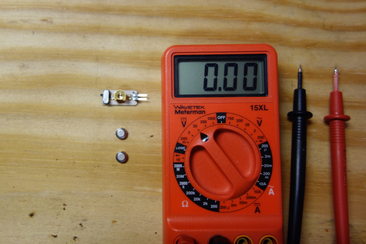
Turn on the switch by flipping the lever up, and measure the voltage across the 2-pin header, the reading should be around 3.1V.
Test the Voltage Regulator Board![]()
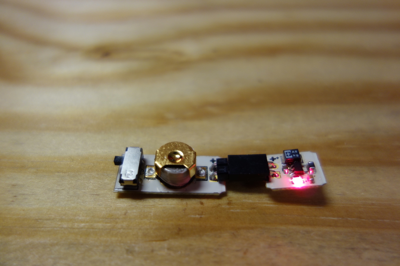
Plug in the battery board to the voltage regulator board, and turn the switch on.
![]()
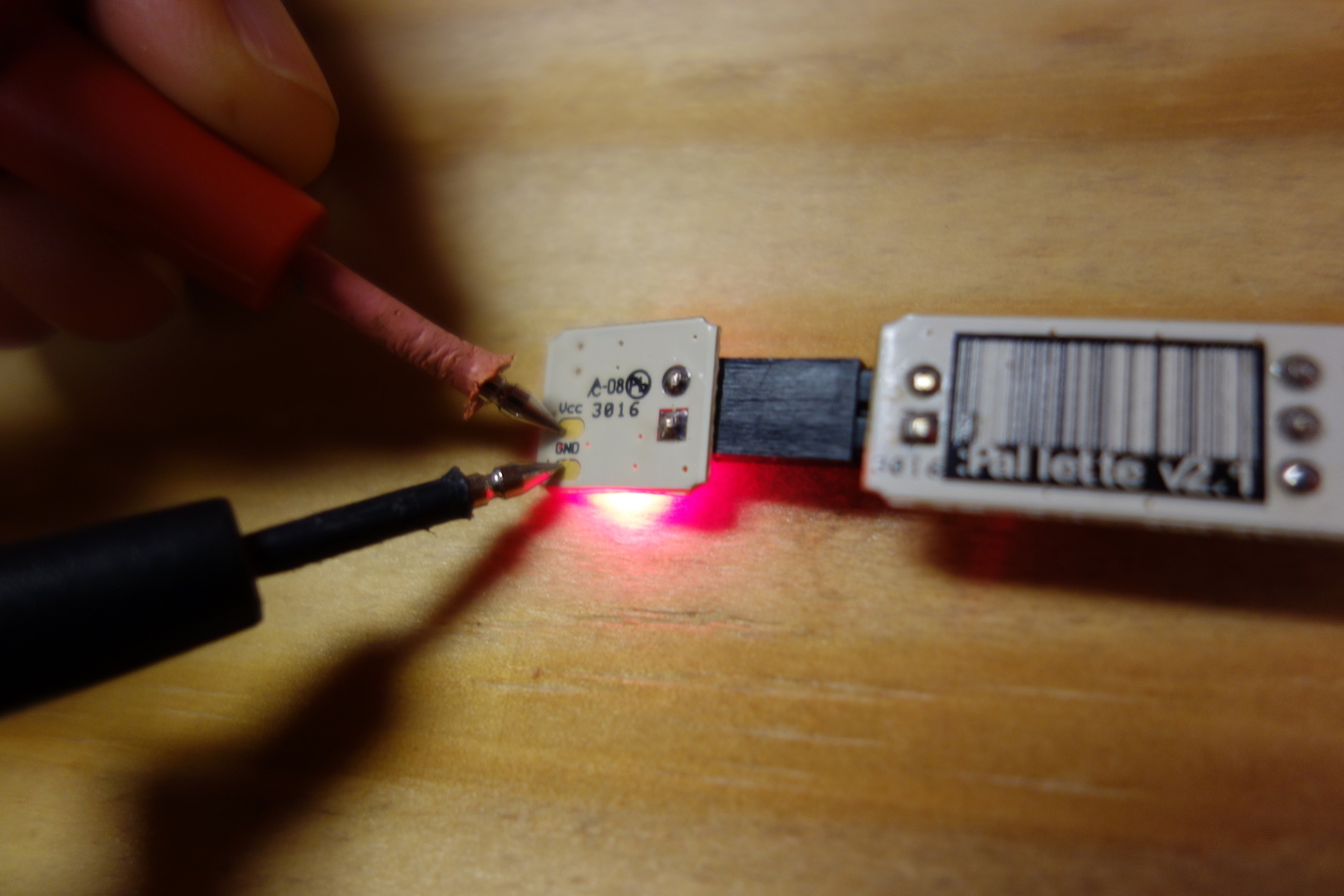
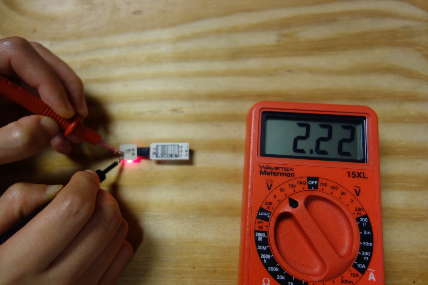
Measure the output voltage from the regulator using the pads on the back of the board. The multimeter should read 2.2V.
![]()
![]()
The Sensor Board and the Microcontroller Board can only be tested in the completed circuit. So next, we're ready to craft the heart of Pallette - the sensor ribbon.
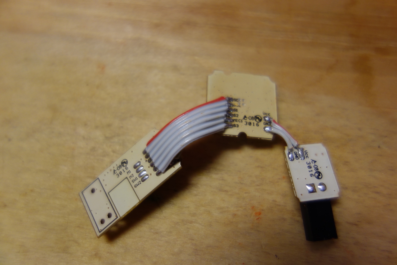
Connecting boardsYou'll align the boards against the clay imprint you made in Step 4, measure lengths and angles for ribbon cables, and solder everything together.
![]()
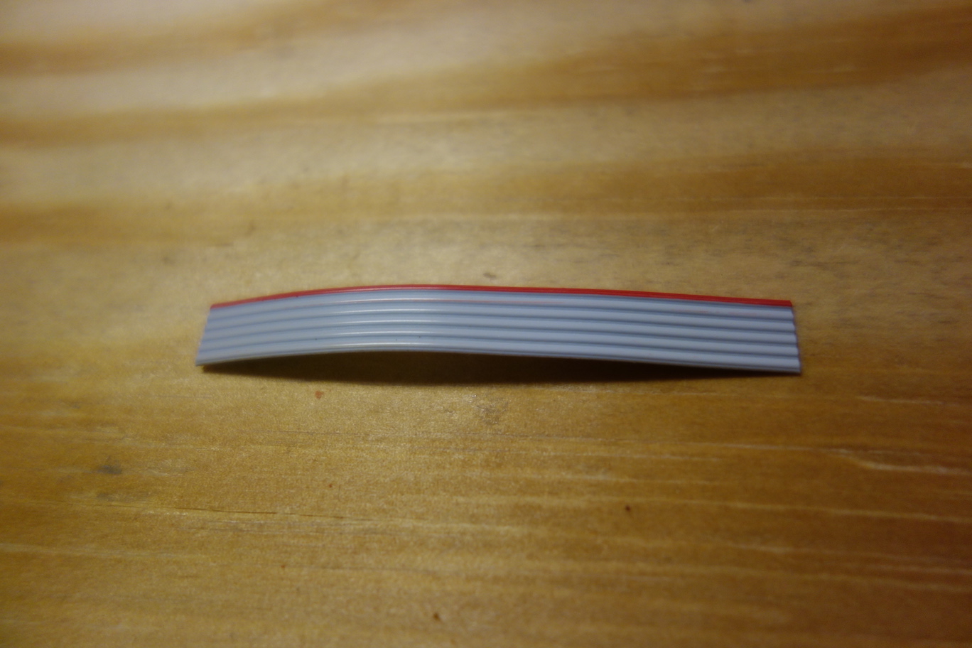
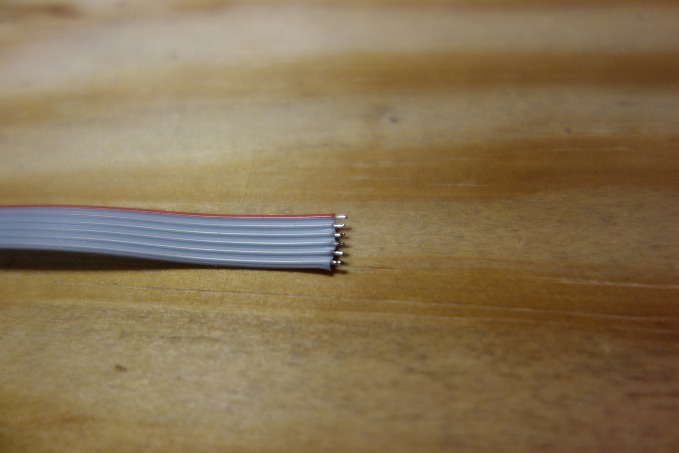
The pads on the back of the boards have a pitch of 0.05", so we will use 0.05" pitch ribbon cables to connect them. We need a 2-conductor ribbon cable to connect the Voltage Regulator Board to the Sensor Board; a 2-conductor ribbon cable and a 6-conductor ribbon cable to connect the Sensor Board to the Microcontroller Board. A 2-conductor ribbon cable can be made from a 6-conductor ribbon cable, by tearing 2 conductors off. The red wire on the cable indicates pin 1. Initially, we cut these three cables to 5cm.
![]()
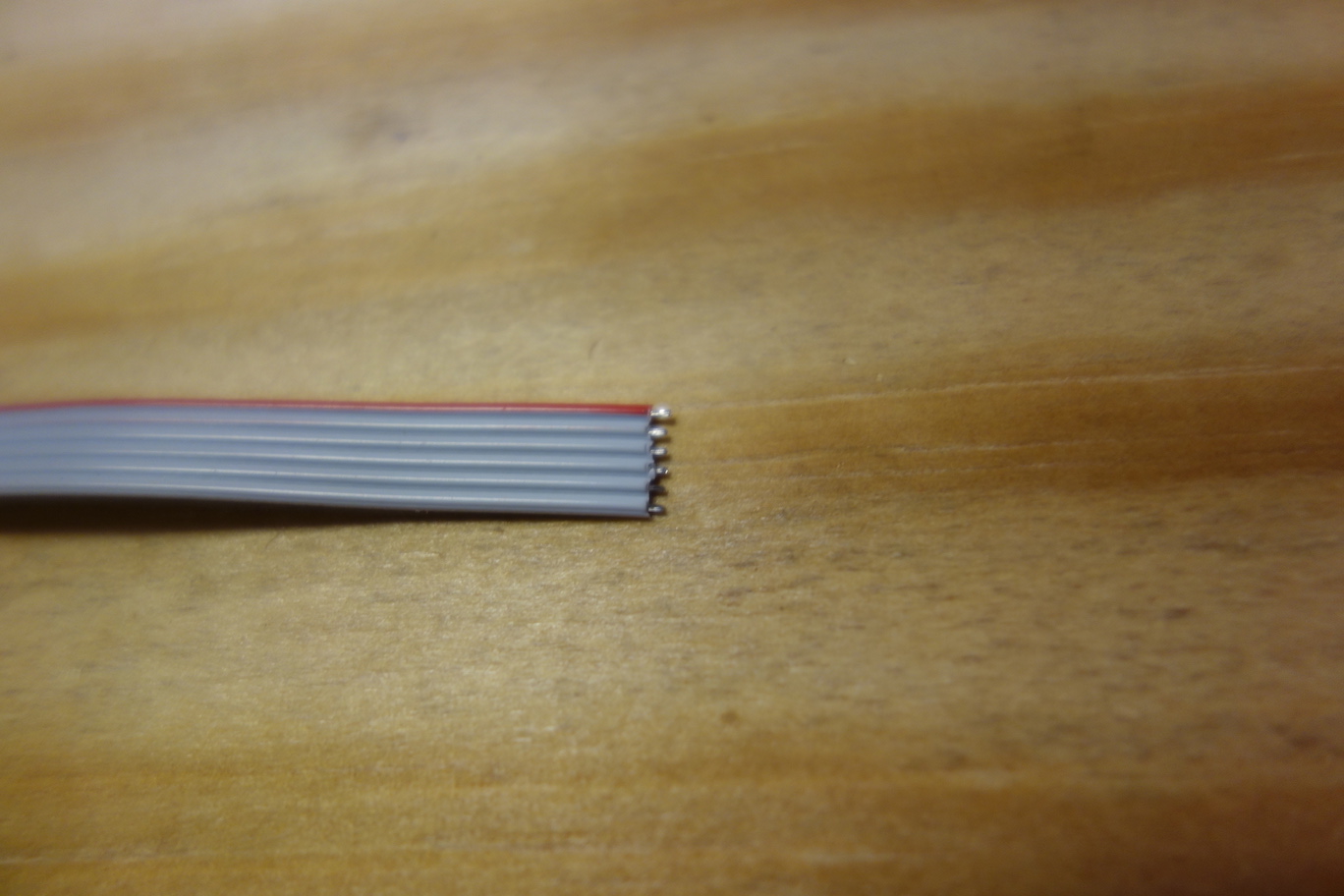
Strip one end of the ribbon cables using wire stripper.
![]()
Turn on the soldering iron, keep the temperature at 250°C (480°F). There are fragile components on the boards, so don't keep the hot iron tip on the boards for too long.
First, we need to tin the wires, so they will be easier to solder. Below is an instruction video on tinning.
Now the wires are tinned.
![]()
Next, we need to solder a 2-conductor cable to the back of the Voltage Regulator Board. Refer to the photo below for the direction of the cable.
It's better to add solder to all the pads first, so it will be easier to solder the wires to them.
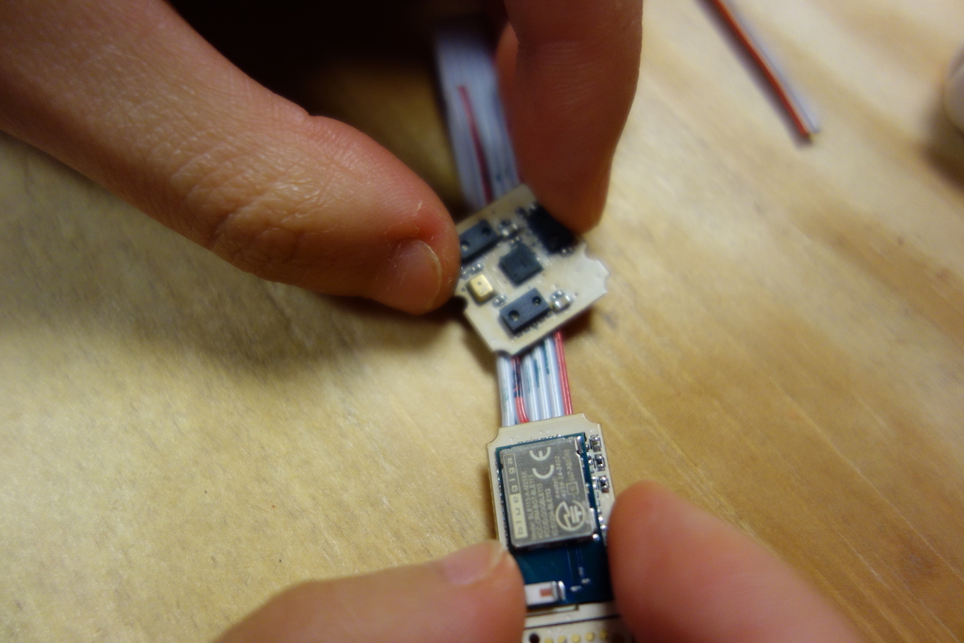
Next, we solder another 2-conductor cable to the back of the Microcontroller Board, and then solder a 6-conductor cable to the Microcontroller Board.
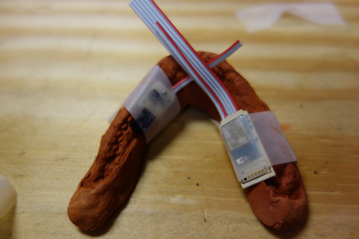
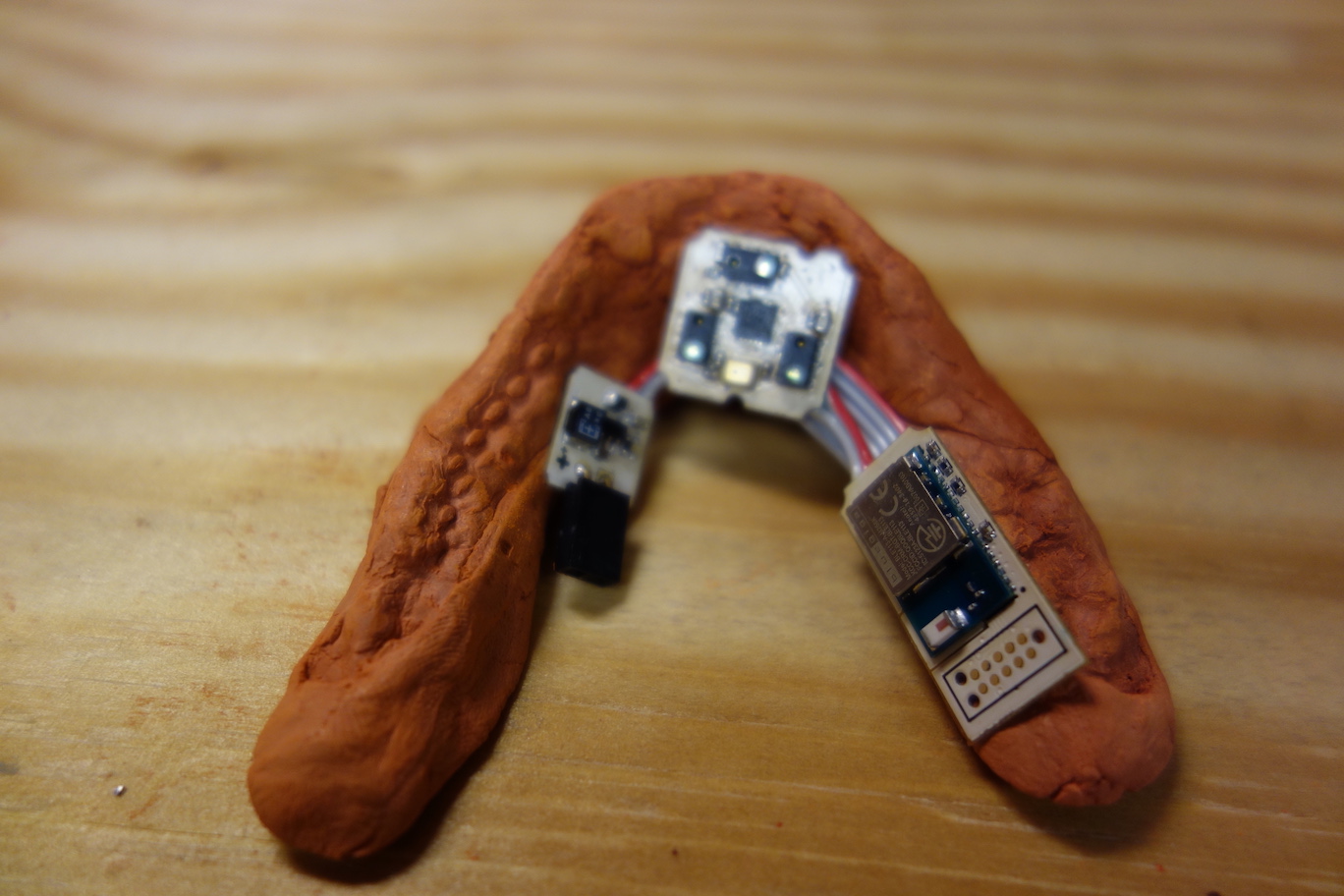
Finally, we tape the Voltage Regulator Board to the left inner side of the clay imprint, and tape the Microcontroller Board to the right inner side, leaving space in the middle for the Sensor Board.
![]()
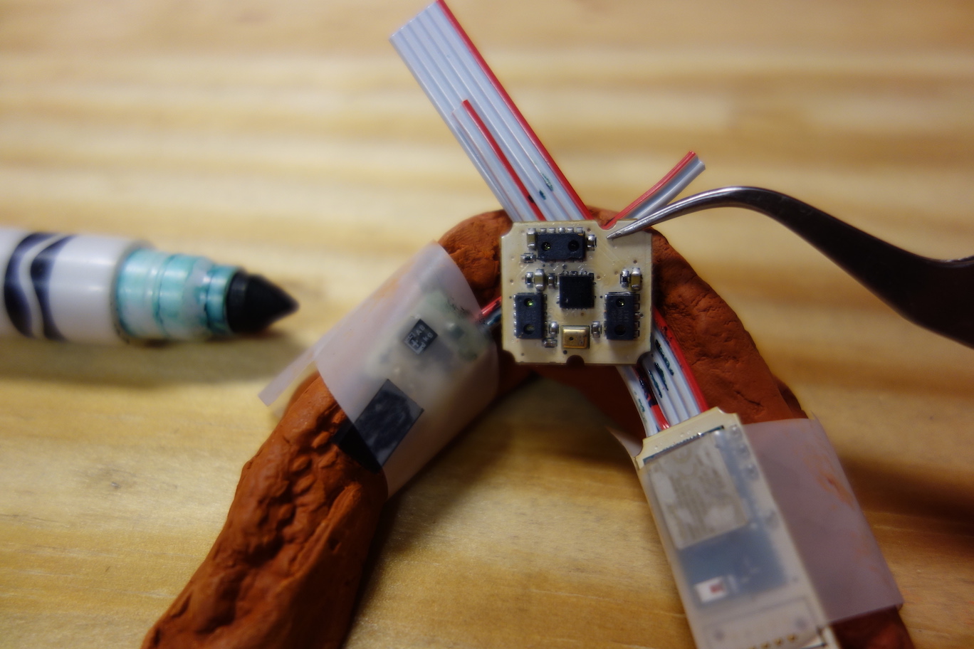
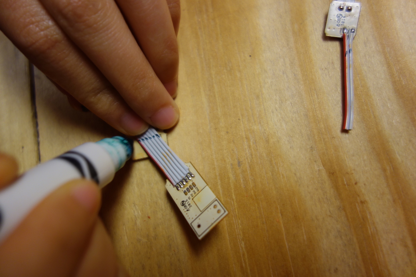
Place the Sensor Board to the middle, refer to the photo below for the orientation of the Sensor Board. Shift the locations of the boards if needed, to get them as close as possible, so the overall length of the Pallette device will be minimum. Mark the edges of the Sensor Board on the cables with a fine tip marker.
![]()
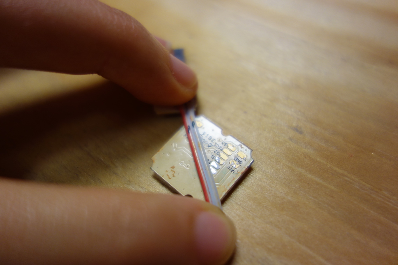
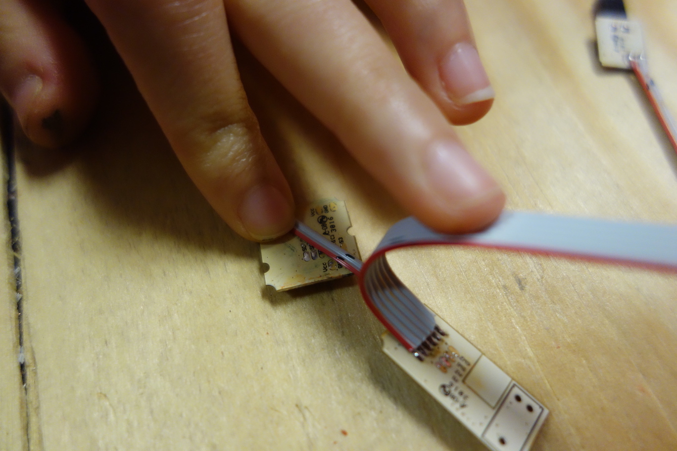
Remove the tapes on the boards. Align the Sensor Board with the Voltage Regulator Board by the marking at the front, then mark the positions of the unsoldered two pads at the left side of the Sensor Board on the ribbon cable, so we know where to cut the cable for the correct length.
![]()
Do the same to determine the correct lengths for the cables on the Microcontroller Board. These two cables go to the right side of the Sensor Board.
![]()
![]()
![]()
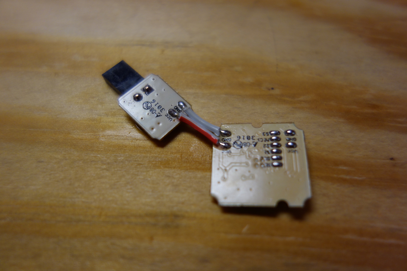
Cut the ribbon cables to the desired lengths, strip the ends, and solder the conductors to their corresponding pads.
![]()
![]()
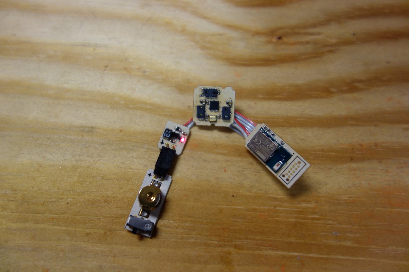
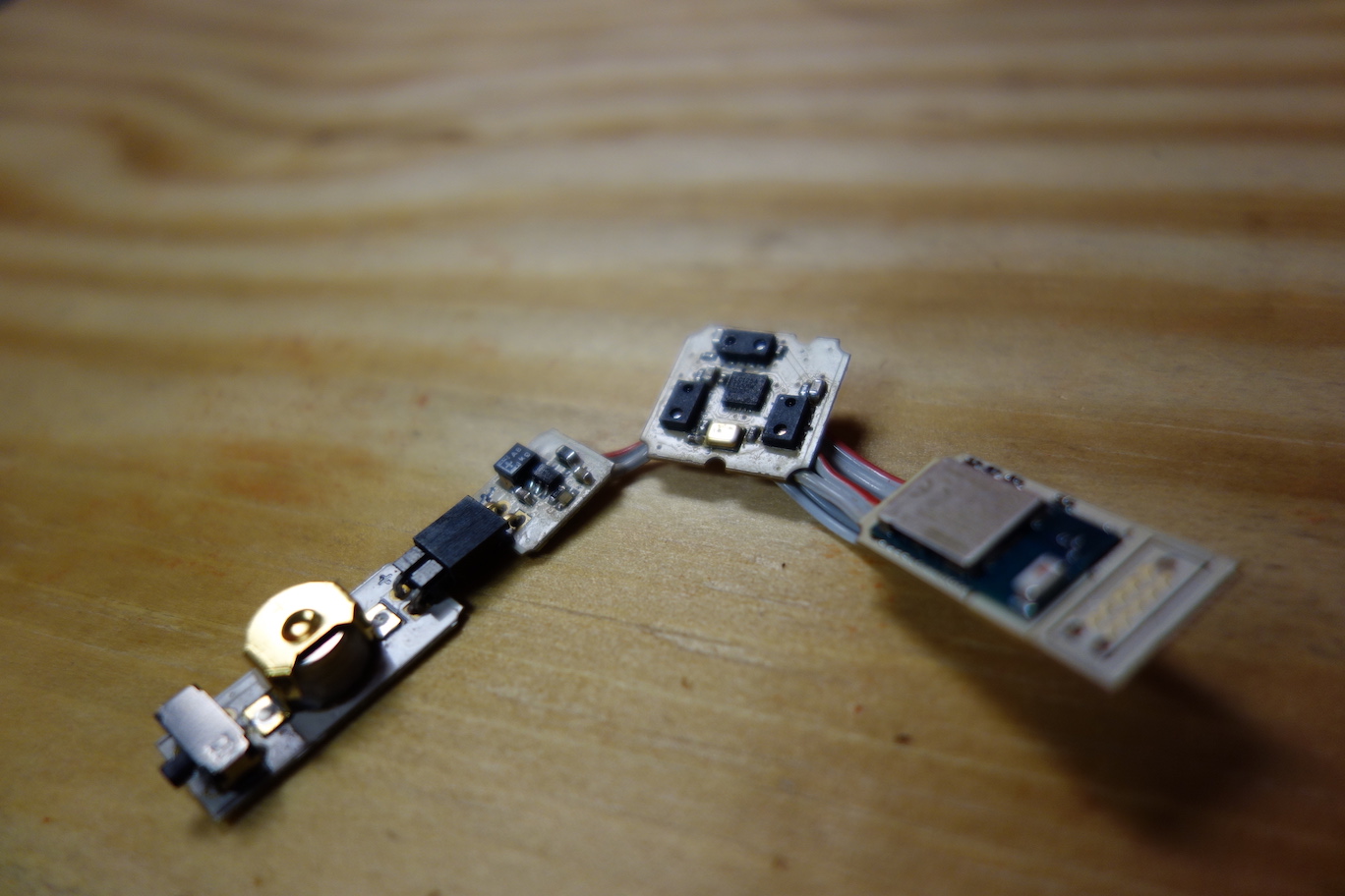
Now we have the Pallette Sensor Ribbon.
![]()
Next, we have to test the Sensor Ribbon to ensure that the circuit functions correctly, before we seal it up. The next step explains how to test the circuit using the firmware and the app.
- The Battery Board
-
7Step 7
http://website.palette.io.s3-website-us-east-1.amazonaws.com/program.html
Program Pallette
What you will need Programming Cable
CC Debugger
CC Debugger Driver
Bluegiga Update Tool
Debugging Firmware
Mouse Controller Firmware
Android Debugging App
Pallette Sensor Ribbon from Step 6
Android Device
Windows Computer or Virtual MachineThe firmware runs on the Bluetooth enabled BLE113 microcontroller. We have made two versions of firmware: the debugging firmware is for checking whether the Sensor Ribbon is working correctly; the mouse controller firmware enables the Sensor Ribbon to control a mouse cursor using your tongue. First, you will need to install the CC Debugger driver, and the Bluegiga SDK on a Windows environment.
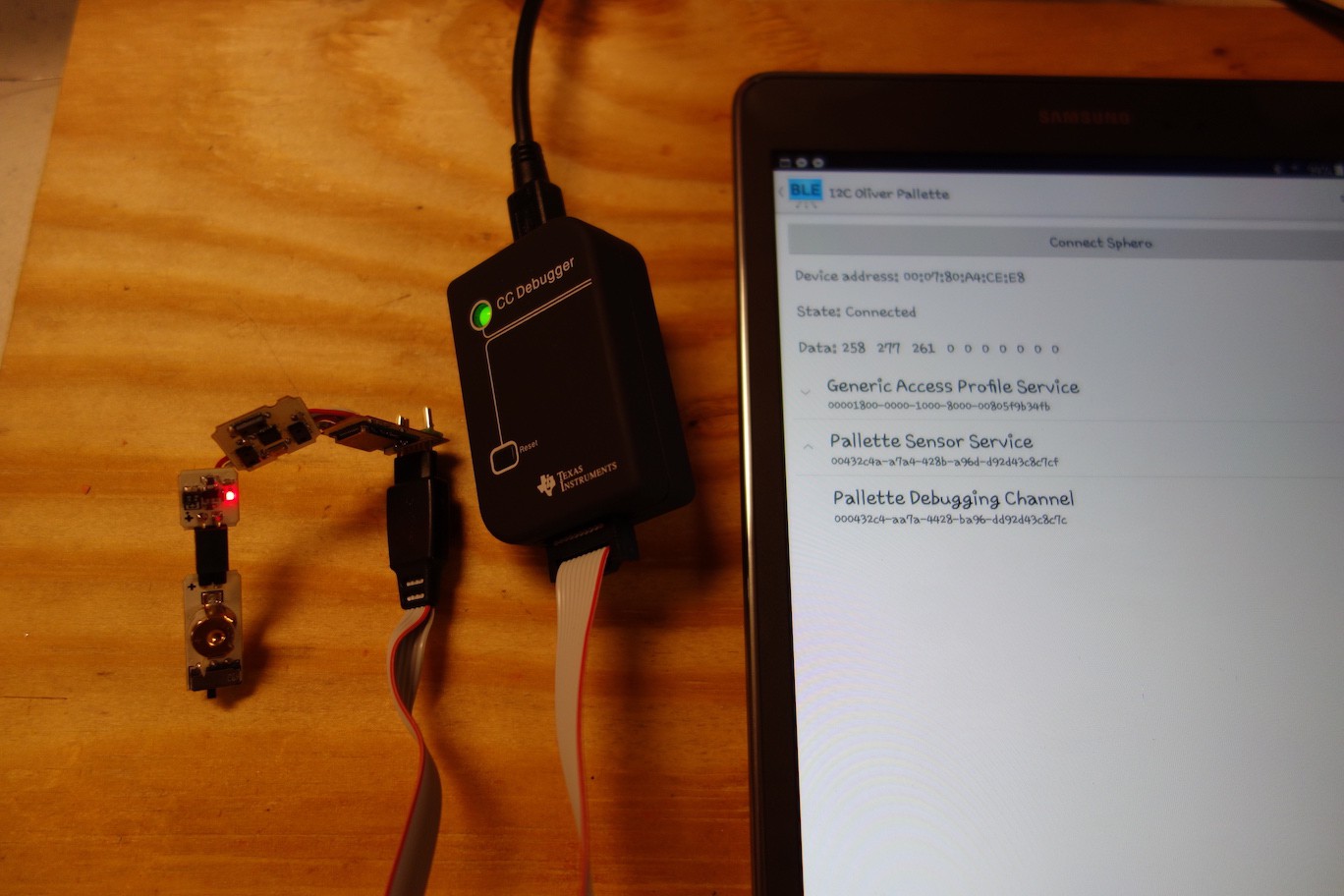
Program the debugging firmwareYou will need to download the debugging firmware files and install the Pallette debugging app on an Android device. The app will display sensor reading values, so you can check whether the Sensor Ribbon is sending correct values or not.
Next, we need to assemble the Sensor Ribbon with the programming cable and the CC Debugger, and connect the CC Debugger to your Windows environment with a mini USB cable. Finally, upload the debugging firmware file to the microcontroller using the Bluegiga update tool. Please watch the instruction video below.
Program the mouse controller firmwareFollow the same steps above to program the mouse controller firmware, or watch the instruction video below.
If the electronic circuit works correctly, now your Sensor Ribbon should be able to control a mouse cursor on a computer or a mobile device. You can try hovering your finger above the Sensor Board, and see whether the mouse cursor follows your finger movement.
The next step is to seal the Sensor Ribbon, so it's safe to use it inside your mouth.
-
8Step 8
http://website.palette.io.s3-website-us-east-1.amazonaws.com/seal.html
Seal Electronics
What you will need Medium Power Heat Gun
acrylated olefin heat shrink
0.5 Nylon tubing
0.5 OD Silicone Suba Stopper
Programmed Pallette Sensor RibbonIt's time to waterproof Pallette and complete the housing.
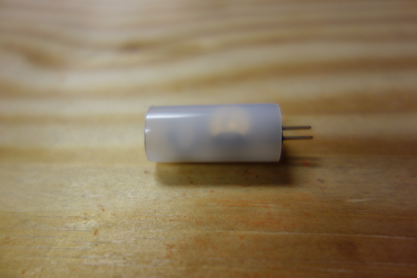
To begin, cut roughly 1 inch of nylon tubing such that it encompasses the Battery Board.
![]()
![]()
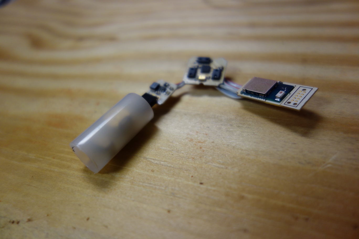
Once this is done, plug the Battery Board back into the Sensor Ribbon.
![]()
![]()
Next, follow the steps in the instruction video below. These steps are also outlined below.
Slide the battery cover tube over the Battery Board.
![]()
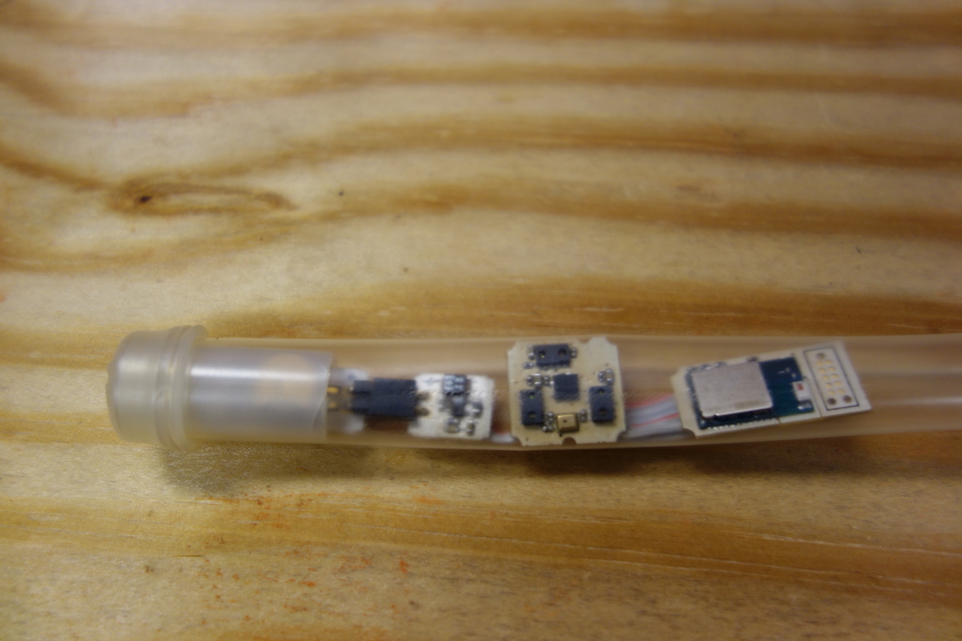
Carefully slide the Sensor Ribbon with battery cover tube into the heatshrink tubing.
![]()
Use the heatgun and clay imprint to shape the final enclosure.
![]()
Heat everything up with a heatgun until full shrinkage. While the end of the heatshrink tubing is heated (feels rubbery) and open on the microcontroller side, clamp it shut with tweezers to seal it. Inspect the seal and cut off excess heatshrink.
Once everything seals, remove it from the imprint, and cap the battery tube with a stopper.
![]()
![]()
Ta-da! Sealing complete! Now to the final step!
-
9Step 9
http://website.palette.io.s3-website-us-east-1.amazonaws.com/sew.html
Sewing
What you will need Suture Thread with Needle
Sealed Pallette Sensor Ribbon
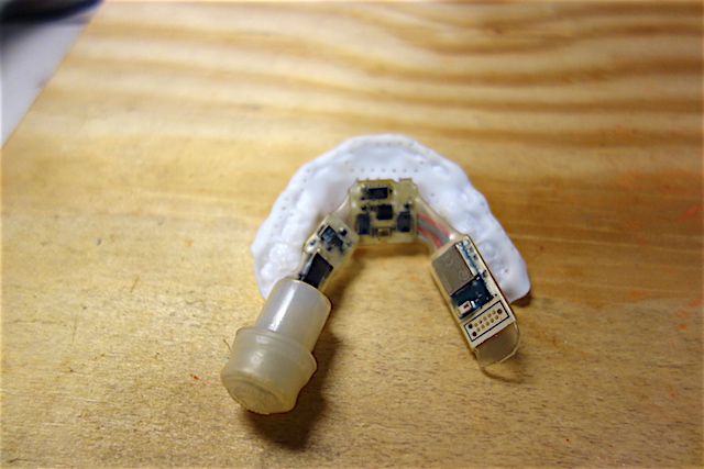
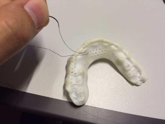
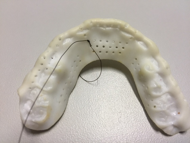
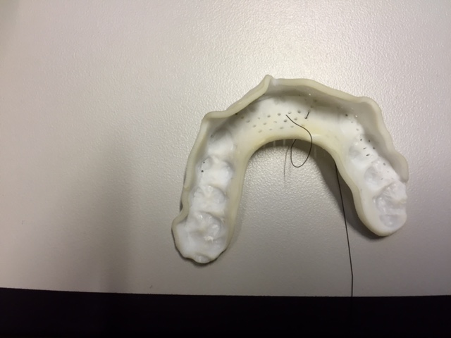
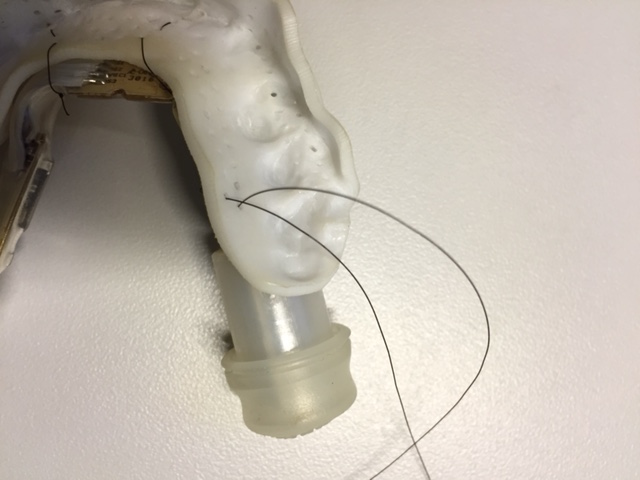
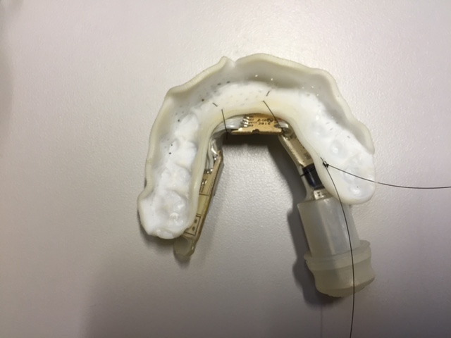
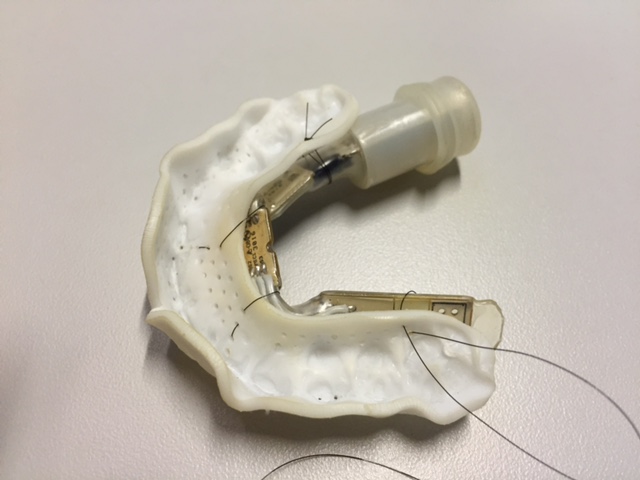
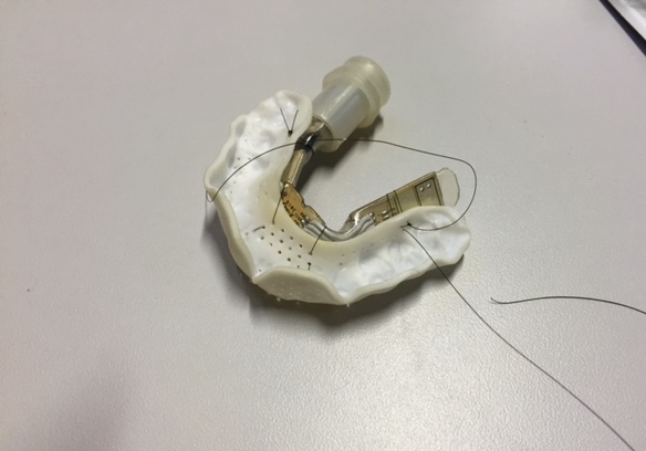
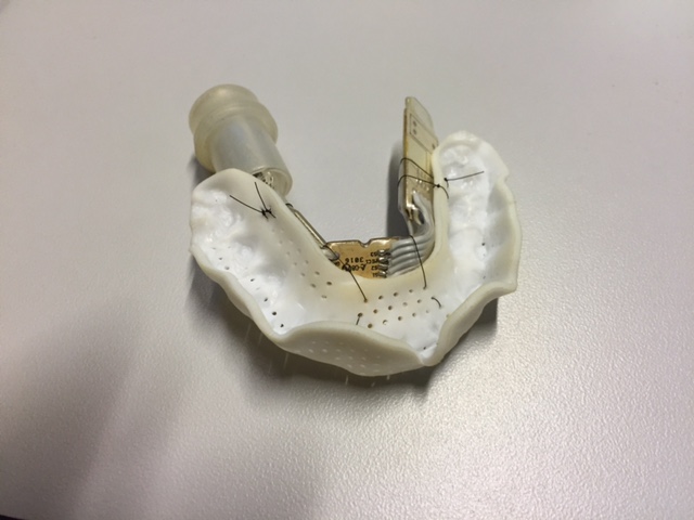
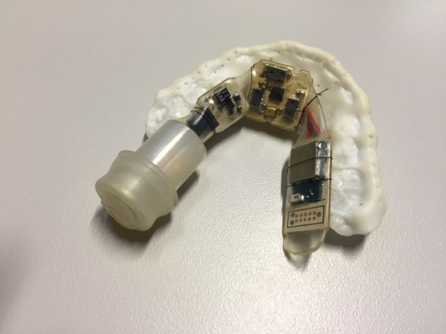
Fitted MouthguardThe final step is to attach the enclosed Sensor Ribbon to the mouthguard. We use suture to sew them tightly together, because suture is biocompatible. You can get creative here, but it's better to sew at the narrower parts of the Sensor Ribbon, and avoid blocking the view of the IR sensors on the Sensor Board.
![]()
![]()
![]()
![]()
![]()
![]()
![]()
![]()
![]()
![]()
![]()
![]()
-
10Step 10
http://website.palette.io.s3-website-us-east-1.amazonaws.com/finish.html
Finish!
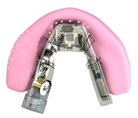
Congratulations! Now you have made your own Pallette! Release your telekinesis superpower with your tongue!
![]()
We see so much potential with Pallette and tongue-control technology, and we hope you agree! The ultimate goal for Pallette is for it to control all technologies important to a user, utilizing internet-of-things. We'd love to have you joining us building a community around tongue-control technology, and helping the people in need.
Please let us know your application for Pallette, and new ideas that can take Pallette further! You can contact us at contact@pallette.io, we'd be thrilled to hear from you!
Pallette
The World's First Open Source Tongue Computer Interface. Empowerment for the Mobility Impaired. Telekinesis with Your Tongue.
 2. A water-tight enclosure
Discussions
Become a Hackaday.io Member
Create an account to leave a comment. Already have an account? Log In.