Andy Osusky
-
Launch
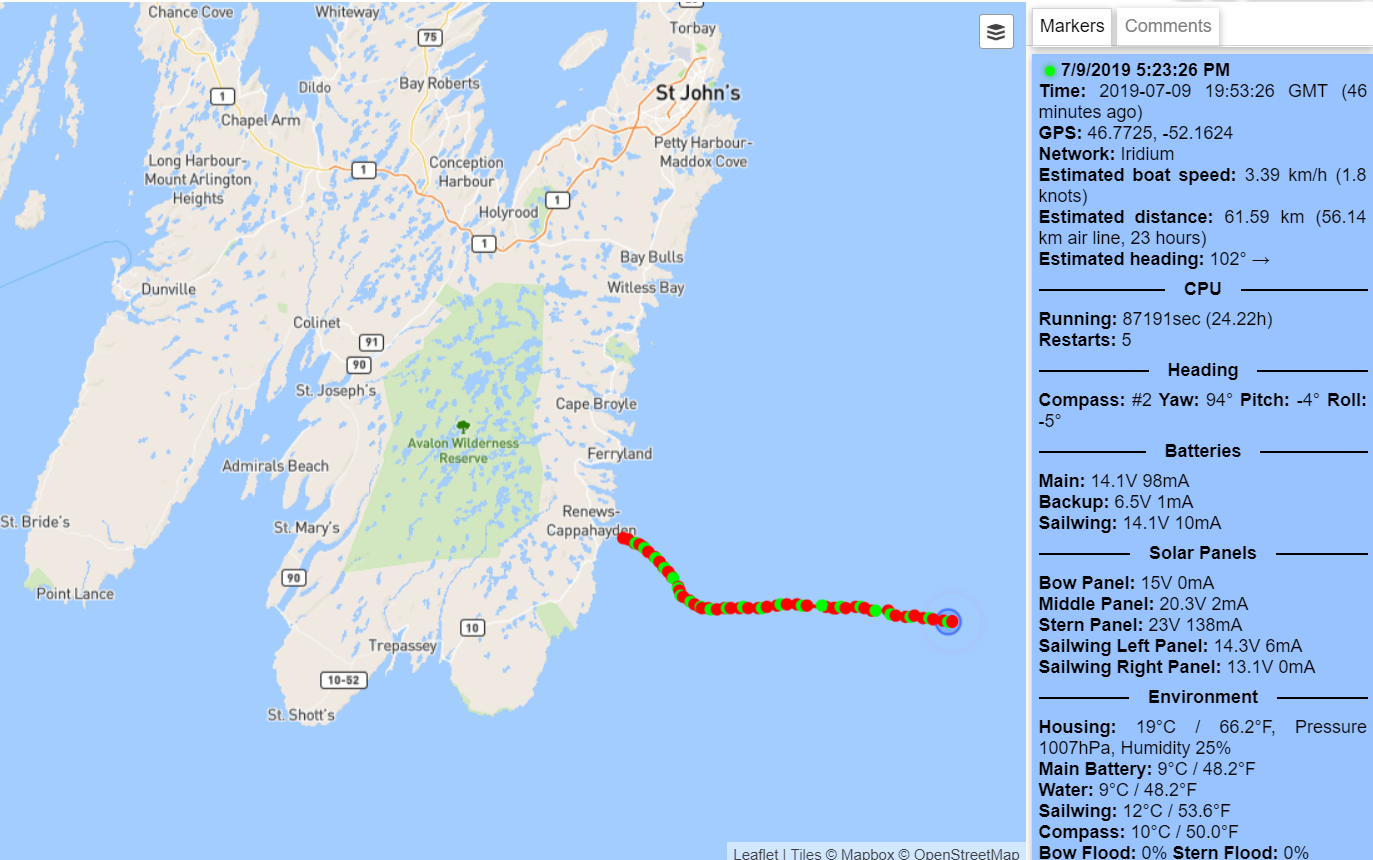
07/10/2019 at 04:06 • 0 commentsThe boat was launched on 8th July, 2019 at 20:46 GMT. So far, so good! You can track it on the map:
It's also reporting plenty of data which you can see by hovering your mouse over any green dot (or by touching it).
![]()
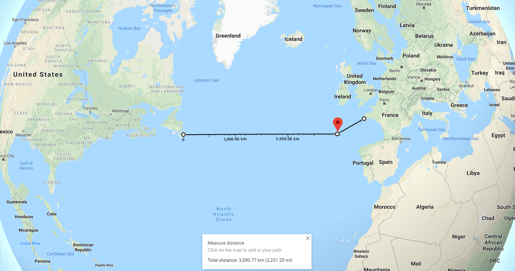
The boat is sailing to the first waypoint 46.75N, 47W that lies on the start line defined by the Microtransat Challenge rules. Now it gets slightly drifted to the south, but it will turn at some point in order to get to the waypoint.
The destination point is 48N, 13W and then it would head to Brest, France.
![]()
I will publish the design files and source code in the next days.
-
Fine-tuning the navigation algorithm
06/17/2019 at 11:07 • 0 commentsThe algorithm has become pretty complex and I use a visualization to simulate how the boat would behave at different locations on the ocean in different wind conditions.
It helped me fix tons of small bugs which I couldn't find by real testing. Here are some interesting points:
- The boat can't sail straight upwind or downwind. In unfavorable wind conditions, it will keep the heading at least 45 degrees to the wind.
- If the wind conditions are unfavorable for some period of time, the boat will follow a zigzag pattern. This way, it can sail upwind as well as downwind.
- If the boat deviates from the shortest path, it will get back to the path rather than going straight to the destination.
- It's most important to minimize the flap adjustments as we are limited by the actuator life-span.
- The boat reacts to the change of the wind almost instantly if the change is confirmed in 3 seconds.
- Most of the time, it will head to the destination plus/minus 7 degrees. There is some tolerance in order to avoid constant steering.
-
How the Sailwing/Tail System Works
06/10/2019 at 07:10 • 0 commentsThis video shows how the sailwing is being controlled by the flap just like an airplane wing.
A powerful fan is blowing air onto the sailwing. When the autopilot sends a wireless command to the actuator that moves the flap, the sailwing starts moving until the flap points in the same direction as the wind is blowing. This way, a relatively small force is required to move the massive sailwing. As Archimedes said: “Give me a lever and a place to stand and I will move the Earth.” Practically, only a 10-degree sailwing adjustment is needed to provide the maximum lift, but as you can see, even 45 degrees is possible. To me, it looks like magic.
Who invented it?
This invention dates back to World War II (Fin Utne's boat Flaunder destroyed by the war) and was used on some manned yachts in 1990's (Walker Wingsail). Today you don't see yachts like this, because traditional sails seem to be more economical. However, an autonomous boat with a wing/tail system came to light in 2004 (the Atlantis project, University of California, Santa Cruz). It's kind of resurrecting a decades-old technology. Now I'm relying on it to cross the Atlantic.
(Source: Catalyst, N16, 2004, Catalyst, N17, 2004, A.Y.R.S. No. 14, 1957)
![]()
-
Lake Testing
05/27/2019 at 06:48 • 0 commentsBelow is a video of the first successful test:
Although the wind wasn't high enough to make thorough tests, the boat was moving through the waypoints. Below is a link to the tracking map.
http://track.opentransat.com/?lake2019
![]()
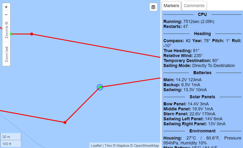
When you hover your mouse over any green dot, you will see plenty of data. The same amount of data will be transmitted from the ocean. To see a short explanation, hover your mouse over any data displayed on the right.
![]()
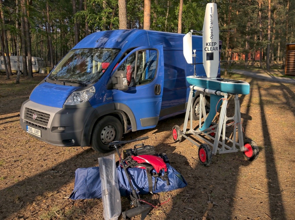
This aluminum support makes the boat easy to transport from my warehouse into the van and then directly into the water.
-
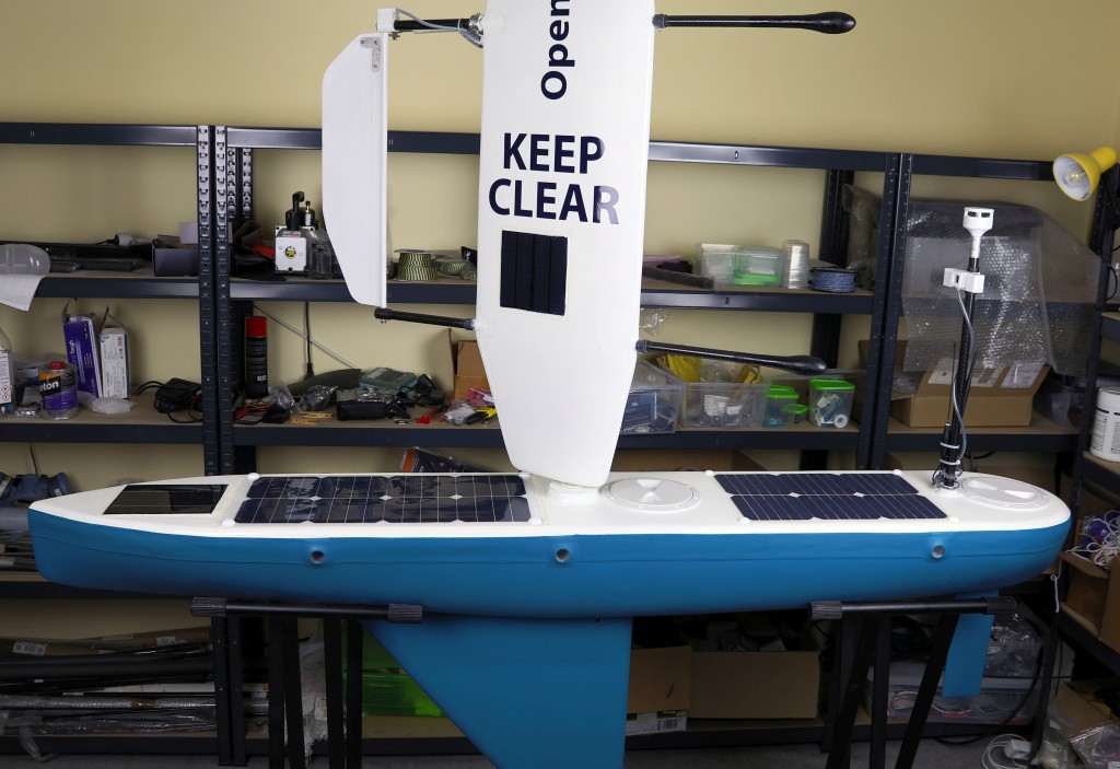
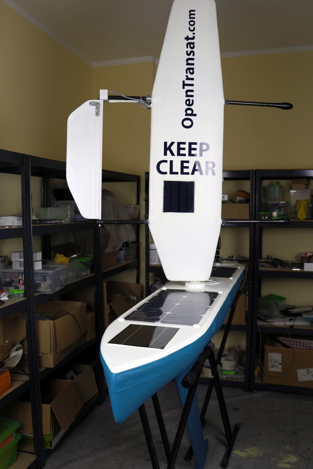
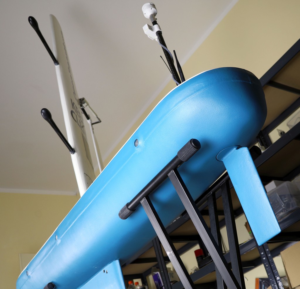
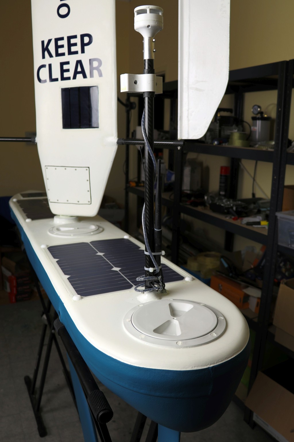
The finished boat!
12/02/2018 at 12:51 • 2 comments![]()
![]()
![]()
![]()
![]()
![]()
![]()
-
The Electronics
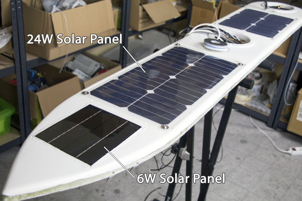
11/26/2018 at 17:55 • 0 commentsSolar Panels And Waterproof Hatches
The solar panels are glued with silicone and two of them are secured with screws.
![]()
![]()
![]()
![]()
The original connector on the solar panel was not IP68 waterproof. I removed the connector, soldered a new cable to the pads, glued a laser-cut acrylic piece with silicone and potted the wire connections with epoxy.
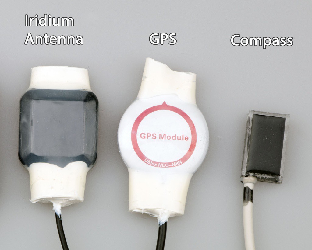
![]()
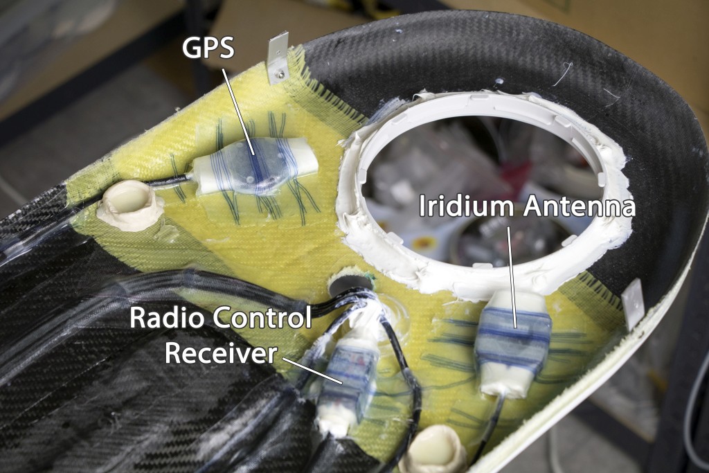
The first three modules in the picture are waterproofed with a heatshrink and silicone. The compass is potted in a heat-conductive epoxy.
![]()
The modules are firmly attached to the deck with a fiberglass tape. I suppose they won't need to be replaced for the lifetime of the boat. The cables are also secured.
![]()
All holes for the screws and cables are potted with epoxy. This is the most reliable sealing method, much better than silicone.
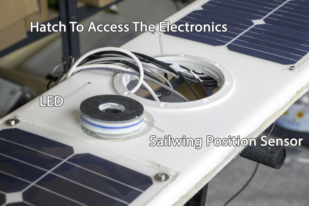
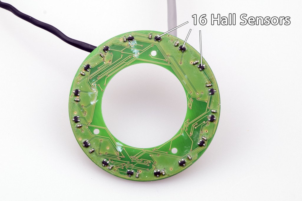
Sailwing Position Sensor
![]()
There will be 16 Hall sensors around the mast which will track a magnet mounted at the bottom of the sailwing. The accuracy is 360 / 32 = 11 degrees or even better with some calibration.
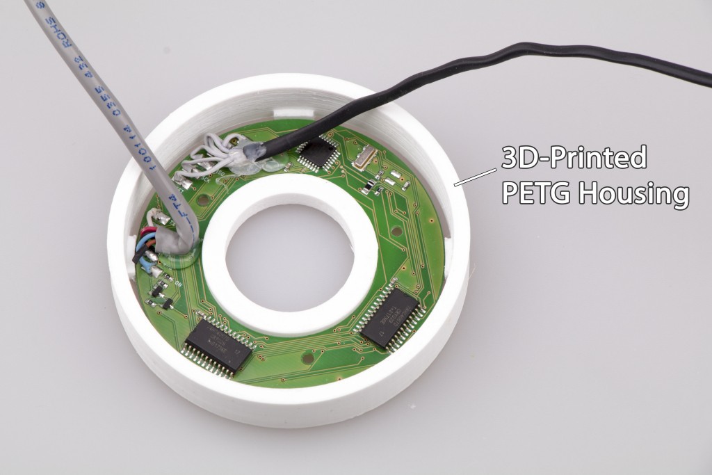
![]()
There is a small CPU that switches between the Hall sensors, crunches the data and sends the result through a serial cable to the main controller. The second cable is for programming.
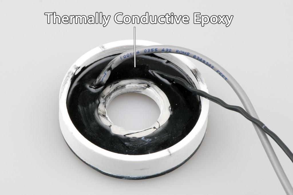
![]()
The PCB is potted in a thermally conductive epoxy, making it perfectly waterproof and shockproof.
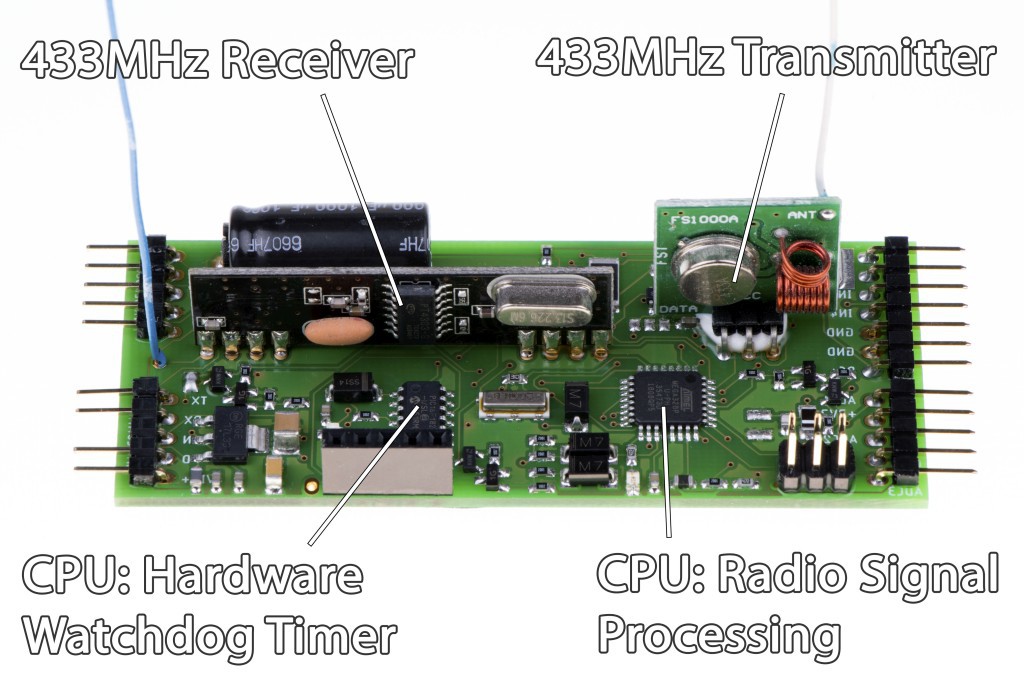
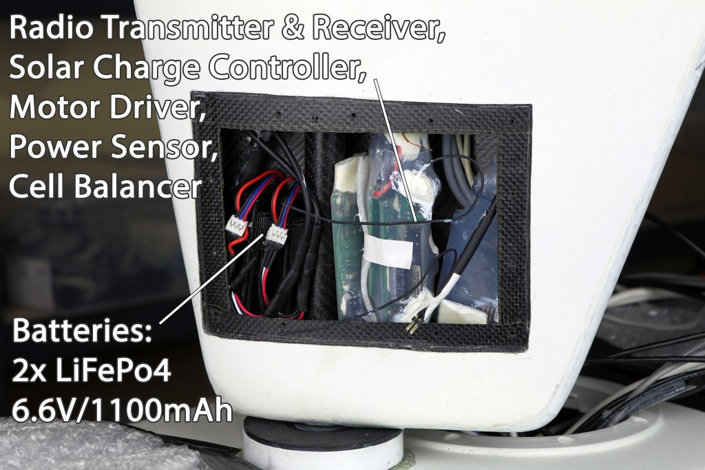
The Electronics Inside The Sailwing
As the sailwing is free-rotating, I had to build a crazy concept where there is no electrical connection between the sailwing and the hull. A cable could easily overtwist and break. Waterproof rotary connectors have a high friction and unknown life span. All the power needed for the actuator comes from the small solar panels mounted on the sailwing. The actuator is controlled wirelessly by commands transmitted from inside the hull.
![]()
All the PCBs are waterproofed with a heatshrink and silicone, so accidental water leakage into the sailwing won't cause any issues. Before the real mission, I will waterproof the batteries and fill the empty space with bubble wrap.
There are two 6.6V / 1100mAh batteries connected in series that are charged by the solar panels. The total current consumption is only 9.5mA. If the actuator adjusts the flap 3-4 times per hour, it will add 1mA to the average consumption. The batteries can provide enough power for 4-5 days without any sunlight if the controller is constantly listening for commands. During a long series of cloudy days, the controller will enter power-saving mode which will increase the response time.
![]()
The controller processes the data from the radio receiver, checks for any errors, controls the actuator position and transmits a response which may include the battery state, solar power, etc. The radio link uses a low-level protocol to eliminate connectivity issues. The main controller inside the hull will repeatedly transmit commands until it receives the response from the sailwing.
In theory, carbon fiber blocks radio signals, but I have tested the controller inside the sailwing and it works.
About the hardware watchdog:
From my experience, a dedicated low-power microcontroller that resets the main controller can solve more potential issues than just a built-in watchdog timer.The Electronics Inside The Hull
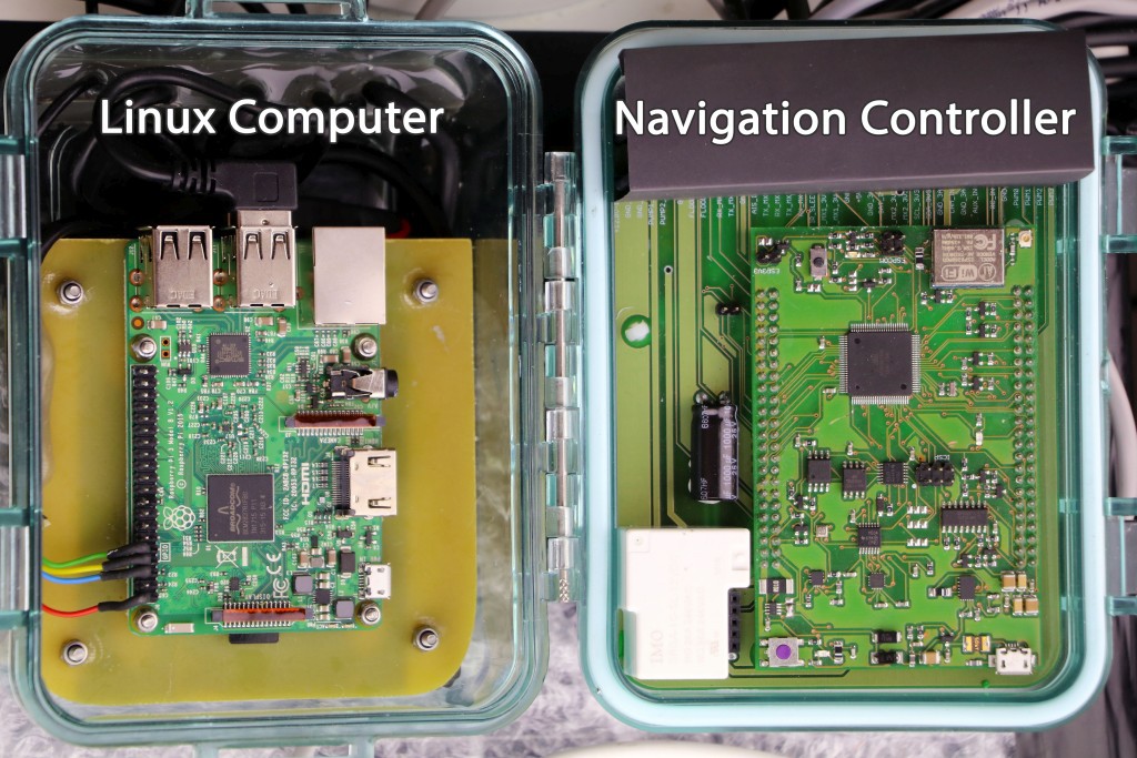
![]()
The electronics is enclosed in a waterproof polycarbonate case. The Linux computer on the left (Raspberry Pi) will record short videos or take pictures from USB camera and store them on an SD card. It may also send compressed pictures through a satellite modem on request. Because Raspberry Pi is power hungry, it will be switched on only when needed.
The custom-built Navigation Controller on the right has been published in another project log a while ago.
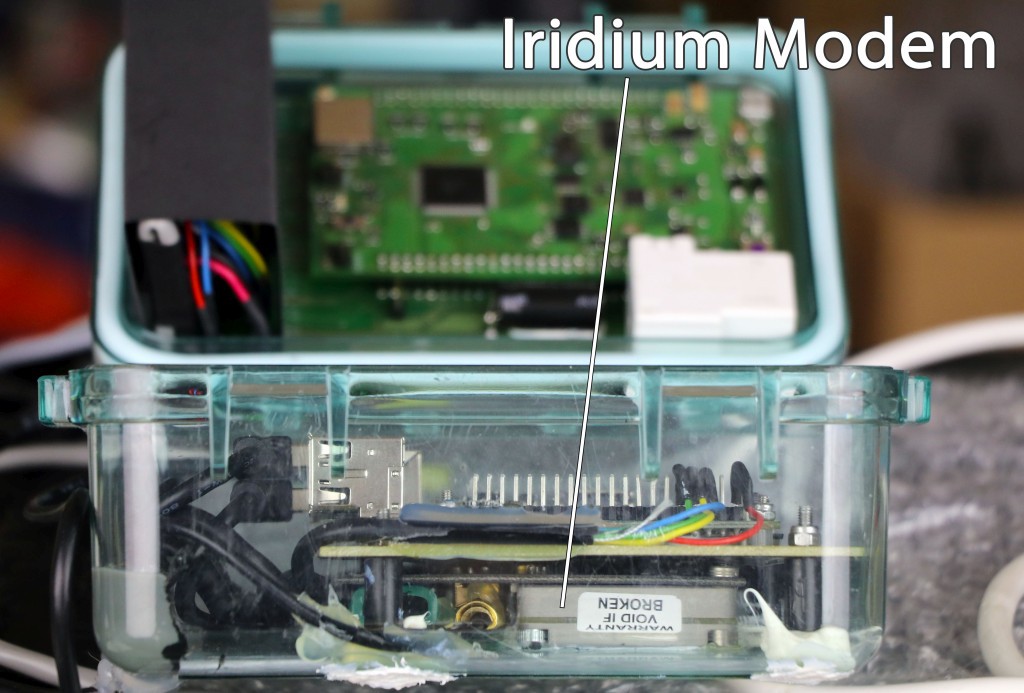
![]()
The Iridium satellite modem (RockBlock) is for transmitting short text messages like GPS position, battery voltage, power output of individual solar panels, data from different sensors, etc.
![]()
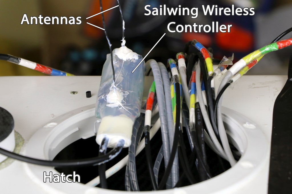
The polycarbonate case can be easily pulled out through the hatch in order to access the electronics.
The sailwing wireless controller will be located somewhere inside the hull as close to the sailwing as possible. It's waterproofed with a heatshrink and silicone.
I find the color codes on the cables very useful to prevent wiring errors.
![]()
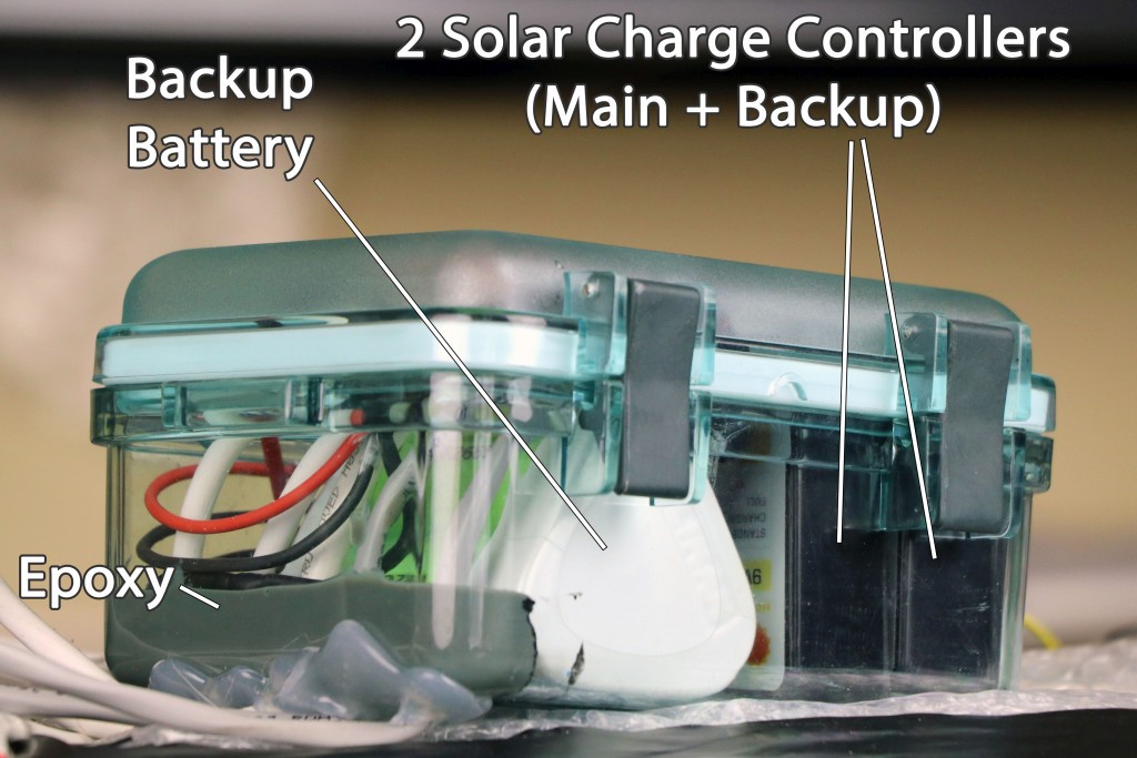
The second polycarbonate case protects a backup battery (LiFePo4 9.6V / 2500mAh) that's independently charged by a secondary solar charge controller. The backup battery will provide power for the secondary tracker that will keep transmitting the boat location even if the main power source fails.
The epoxy-sealed cable pass-through makes the housing perfectly waterproof for full submersion.![]()
The waterproof connectors are used as switches to disconnect all power sources from the electronics.
The solar power sensor is a PCB potted in a thermally conductive epoxy. Its function is measuring power output of individual solar panels and reporting the data to the main controller. It must be kept outside the polycarbonate housing as the blocking diodes may get pretty hot. More details on GitHub: https://github.com/OpenTransat/PowerSensor
-
Rudder & Keel
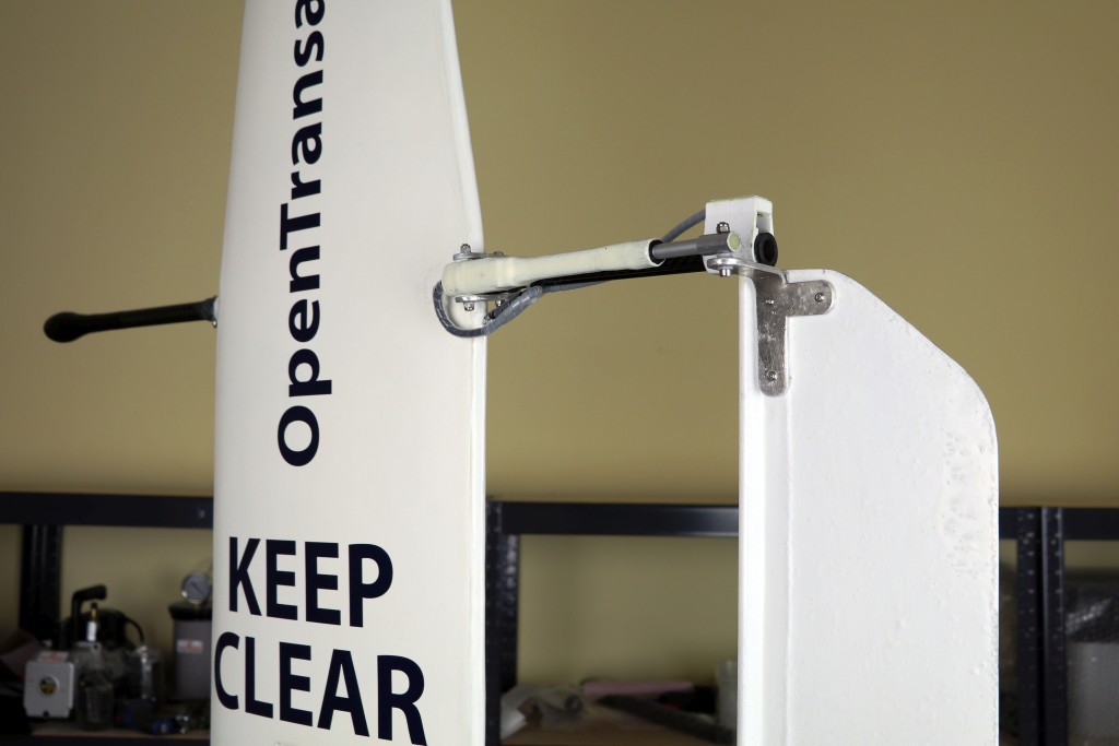
07/05/2018 at 07:28 • 0 commentsSymmetrical Rudder
This rudder is (semi-)symmetrical, i.e. reduces the power needed to steer the boat and avoids entanglement around the rudder shaft.
![]()
![]()
![]()
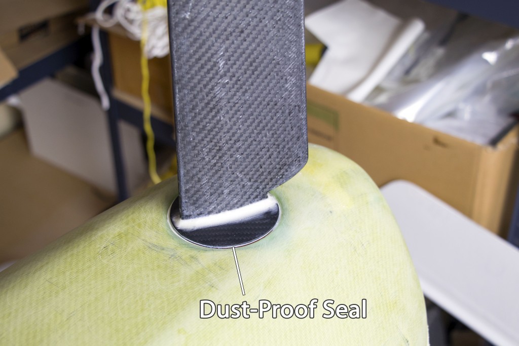
The rudder has a flange that fits in the cavity on the hull surface. The dust-proof seal (a thin flexible silicone sheet) prevents small particles from entering into the cavity.
How the rudder was built
![]()
![]()
![]()
![]()
Rotary Shaft Seal
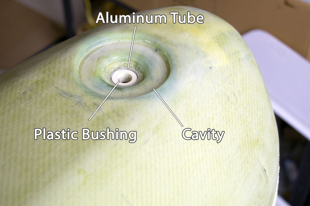
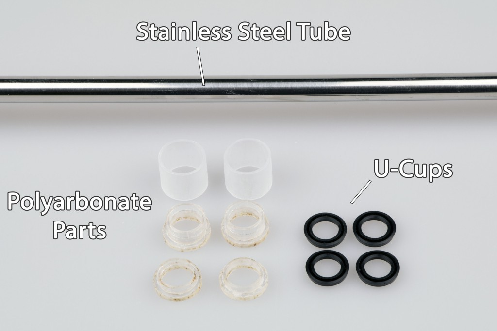
The rudder shaft is made from a polished stainless steel tube that has a good adhesion to the rubber u-cups. U-cups are special o-rings designed for rotary shaft seal.
![]()
![]()
The u-cups are inserted into polycarbonate tubes which are glued inside the aluminum tube that is part of the hull skeleton. I didn't insert the u-cups directly into the aluminum tube because aluminum doesn't have as smooth finish as polycarbonate. It's all designed in a way that I can easily replace the u-cups.
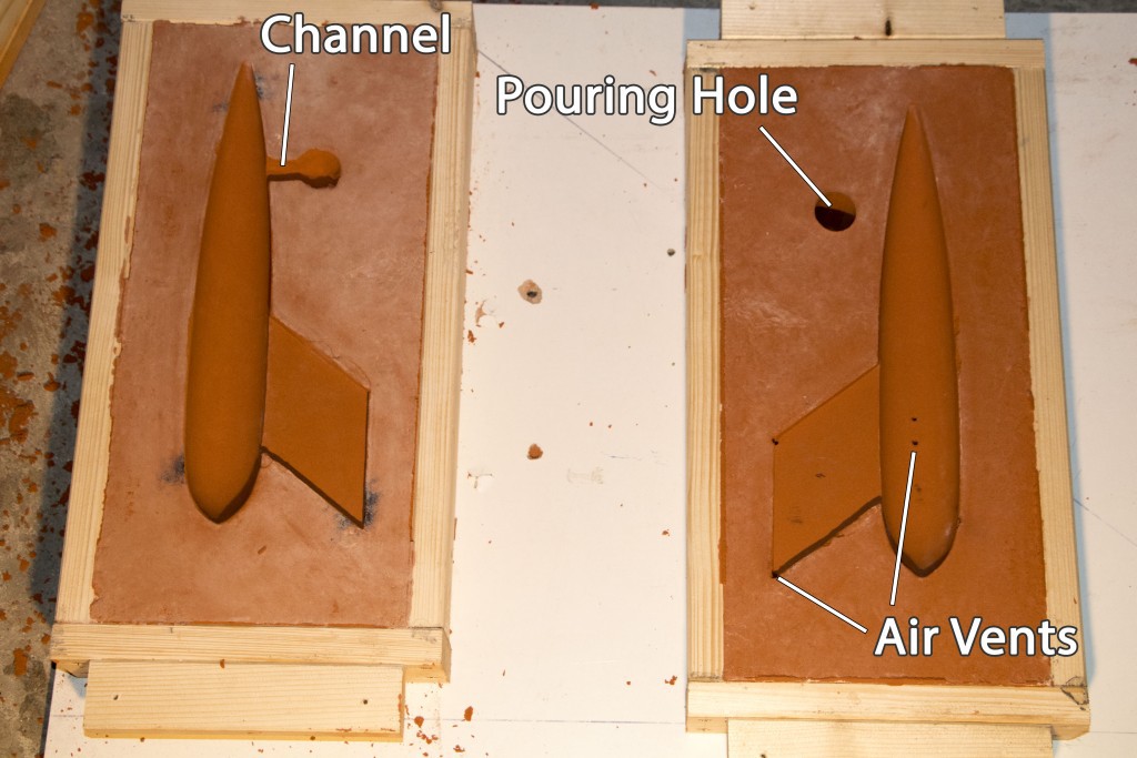
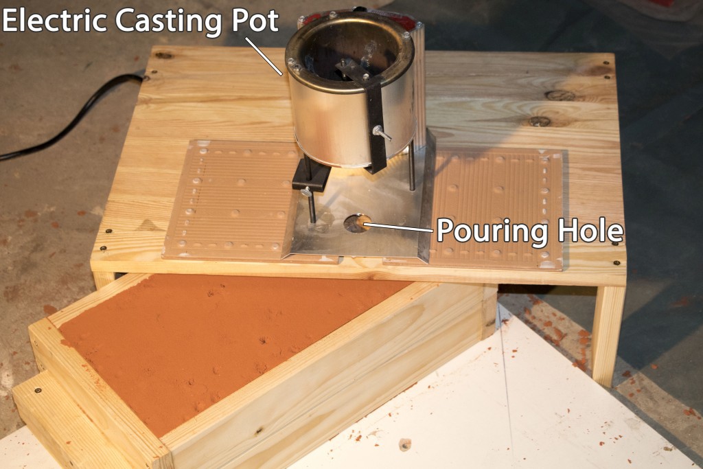
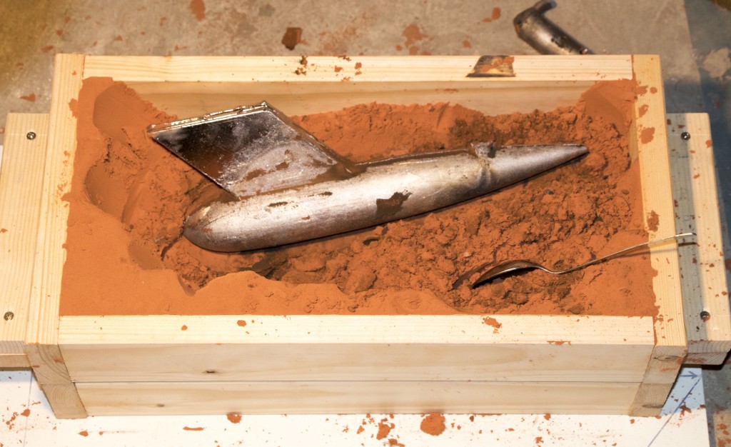
Lead Casting
For casting the lead bulb, I found a couple of video tutorials on Youtube. It's the first time I'm doing this and I'm pleased with the result!
![]()
![]()
![]()
![]()
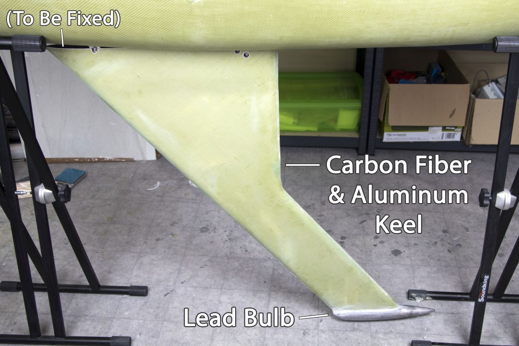
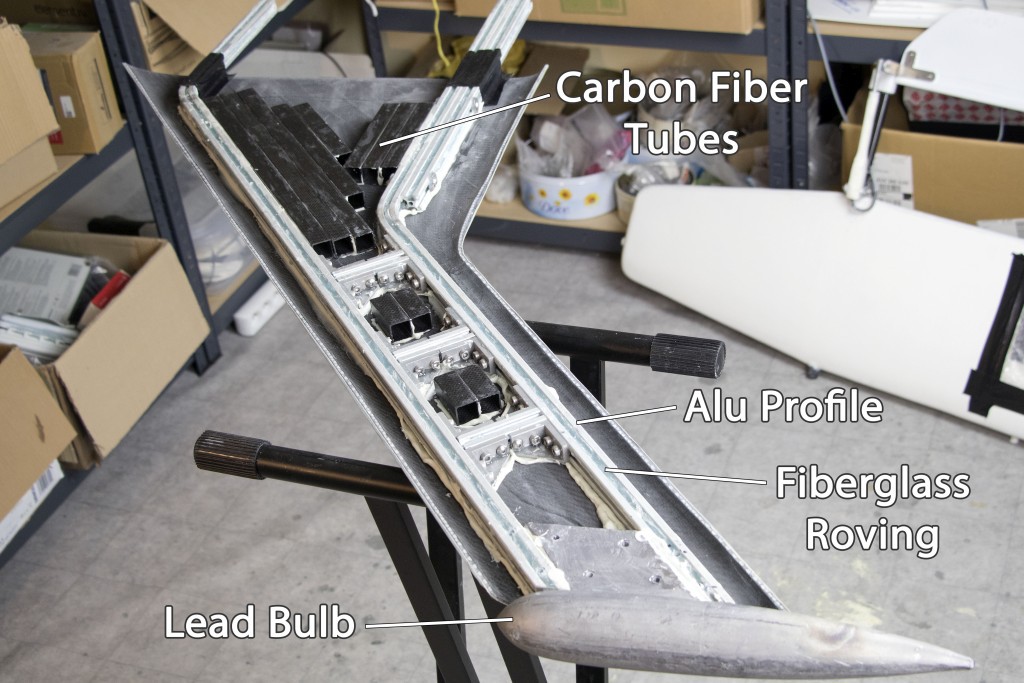
Removable Keel
The carbon fiber keel was made using resin infusion as shown in another project log.
![]()
To make the keel even stronger, there is an inner skeleton made from aluminum profiles reinforced by fiberglass roving. The primary purpose of the skeleton is to attach the keel to the hull. All parts were glued together with epoxy putty.
![]()
![]()
-
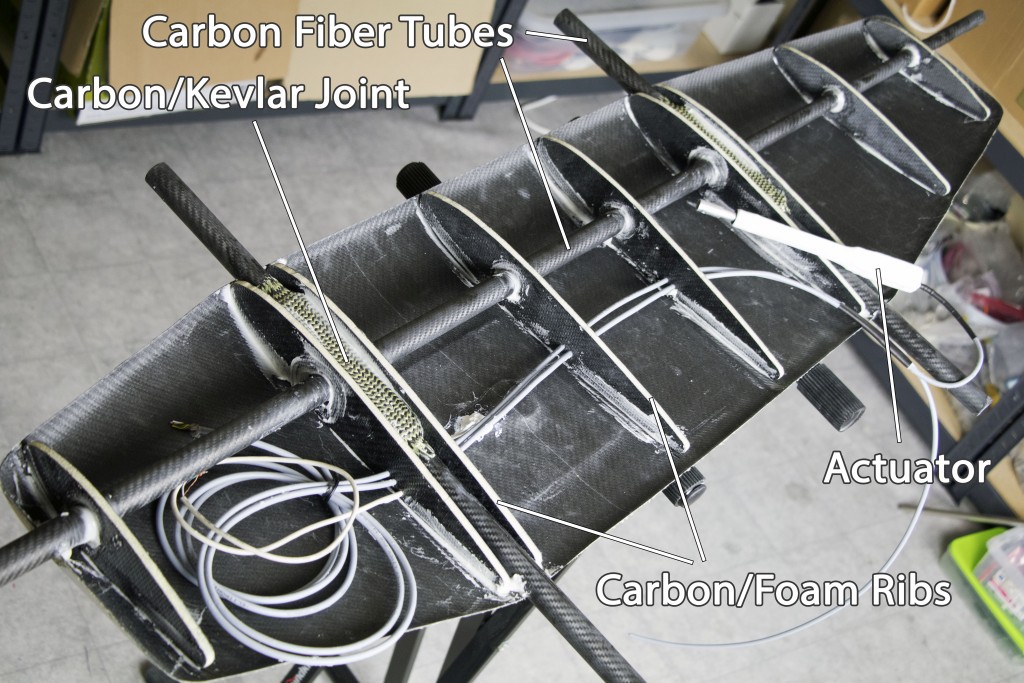
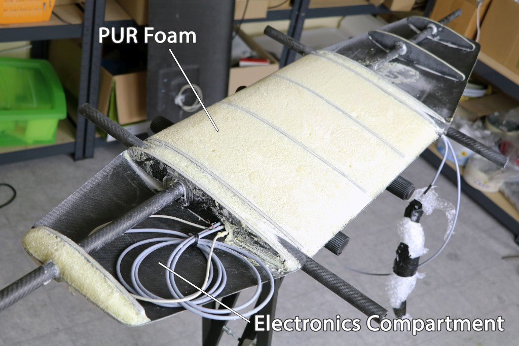
The finished sailwing
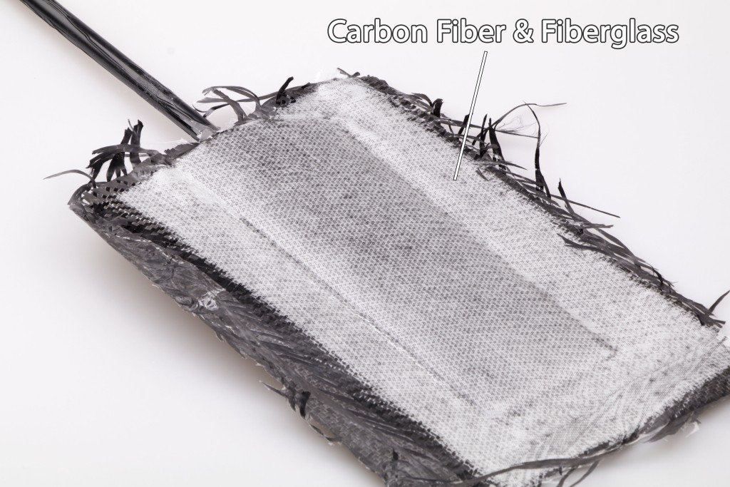
05/28/2018 at 07:04 • 0 commentsThe two resin-infused carbon fiber parts as seen in the project log were joined together with epoxy putty and waterproofed with a fiberglass tape. The inner skeleton makes the sailwing really robust.
![]()
![]()
![]()
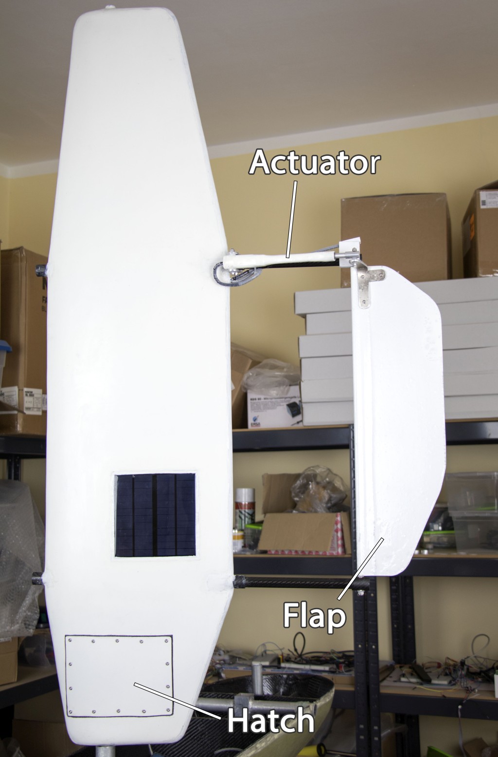
Sailwing Control
The sailwing orientation is controlled by a flap that is adjusted by a waterproof actuator. Here's a video how it works:
The actuator has a potentiometer that provides a position feedback. However, in my endurance test, the potentiometer was the first thing that failed. I found it's going to be pretty easy to mount a magnet on the end of the flap shaft and use it for a more reliable position feedback.
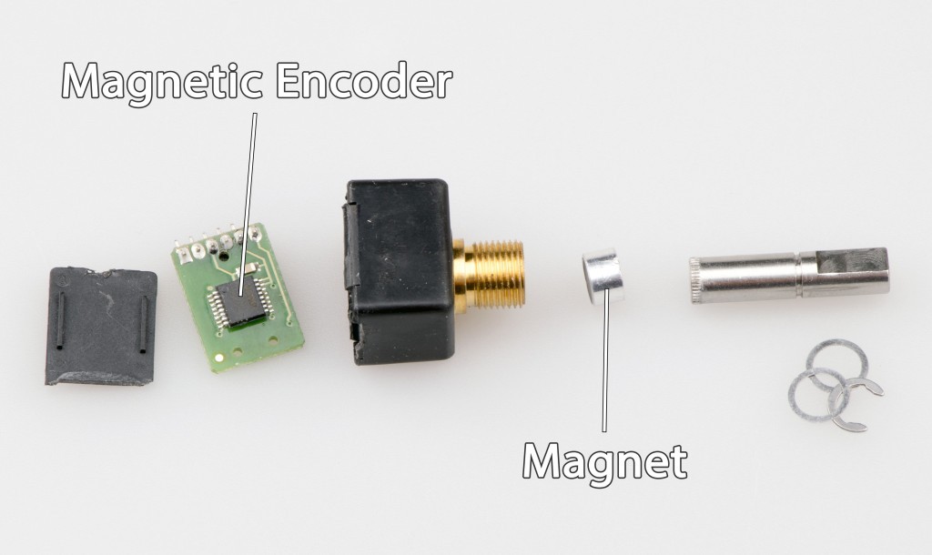
Magnetic Encoder Teardown
![]()
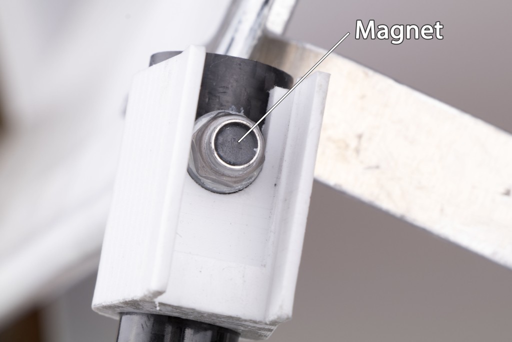
The magnet fits into a standard M6 nut after the nylon collar is removed. I glued it all together with a marine epoxy.
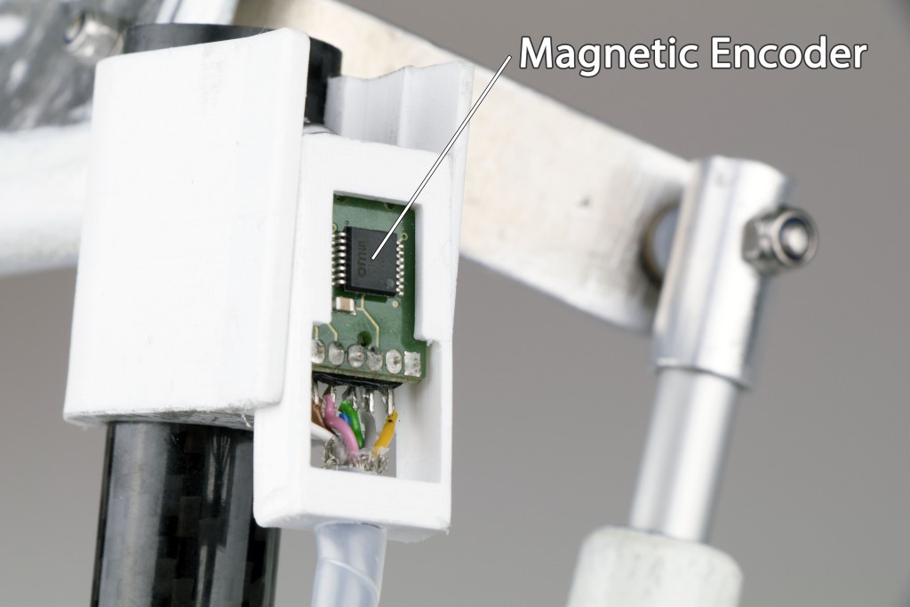
![]()
I 3D-printed a PETG housing for the encoder PCB. The PCB will be potted with a heat-conductive epoxy compound.
![]()
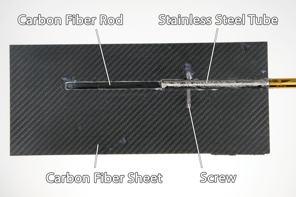
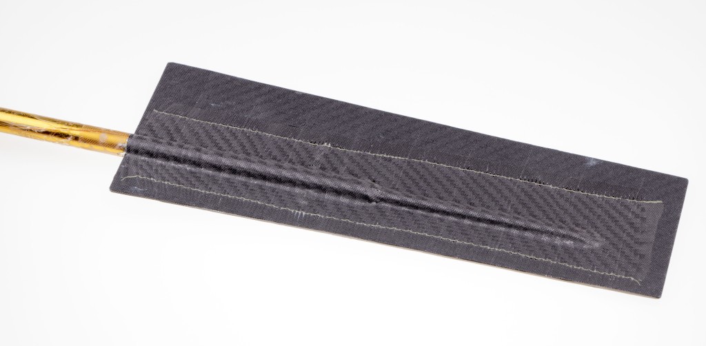
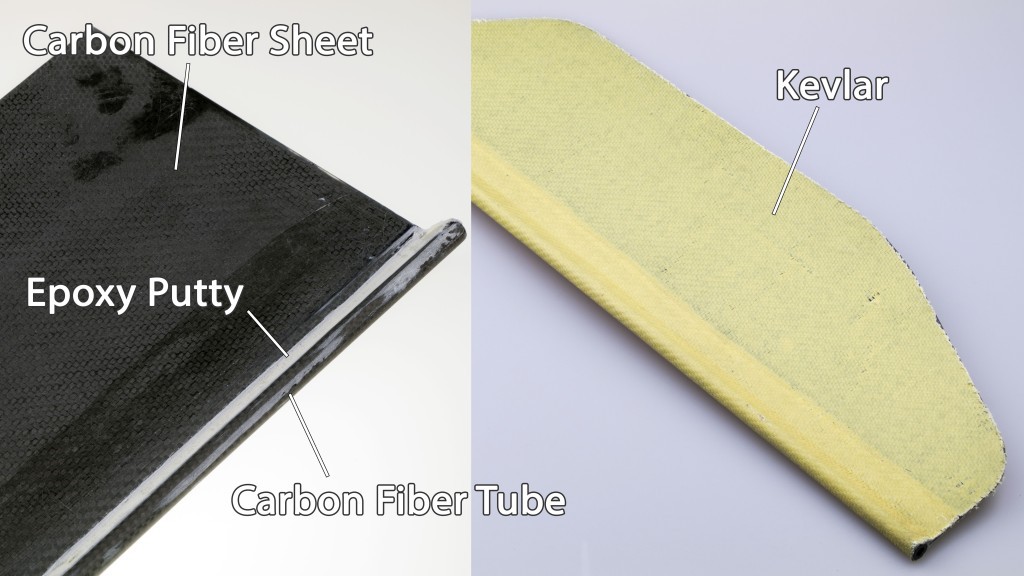
Finally, here's how the flap was built. A 1-mm carbon fiber sheet is glued to a carbon fiber tube and wrapped with Kevlar.
![]()
The next thing to do is a sailwing position sensor that's designed as multiple Hall sensors around the mast. It will act as a backup wind sensor.
-
Hacking a linear actuator
05/14/2018 at 06:45 • 0 commentsThe actuator for sail control has to be small, lightweight and waterproof for full submersion. There are no great requirements for strength and life span as the force needed to adjust the flap is relatively small and it will move only when the wind direction reverses which may happen max. once per hour. In the following video, a hacked actuator was completely submerged in a concentrated salt water and tested for 3000 cycles.
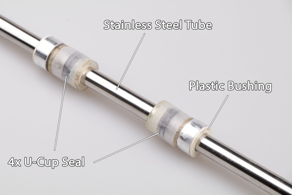
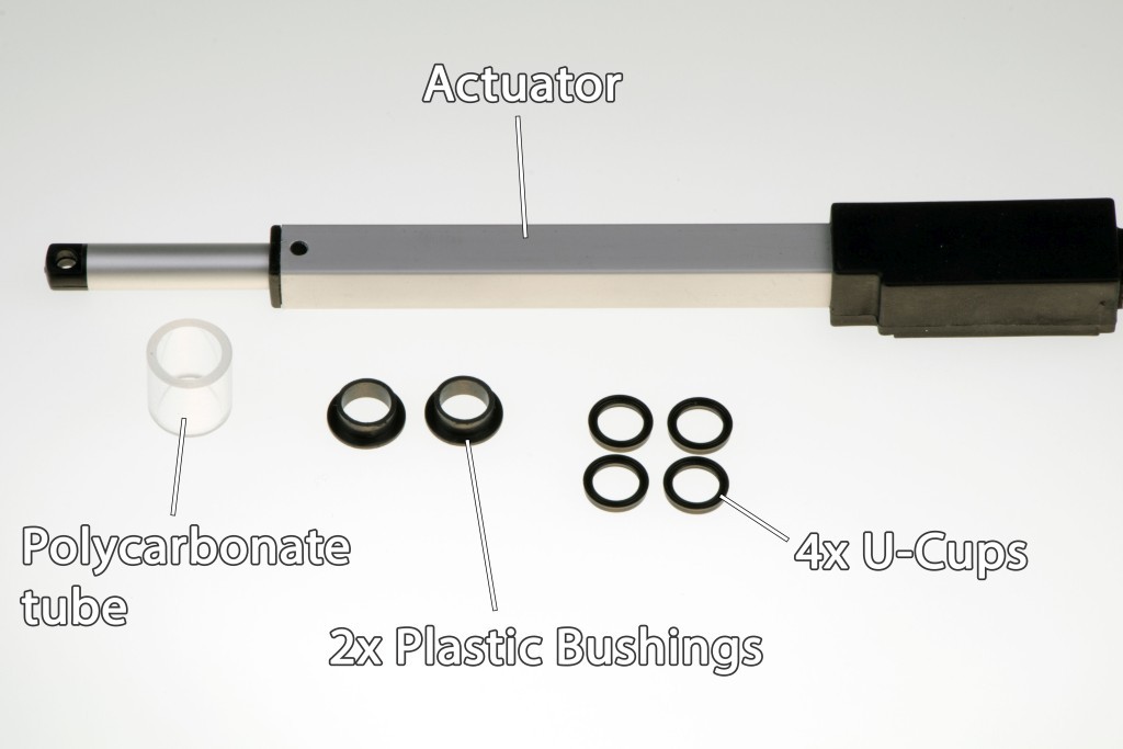
How to waterproof the actuator
![]()
You need u-cup seals, plastic bushings and a piece of tube with a smooth inner surface, preferably a polycarbonate tube. The inner diameter of the u-cups must match the diameter of the actuator rod and the inner diameter of the tube must match the outer diameter of the u-cups.
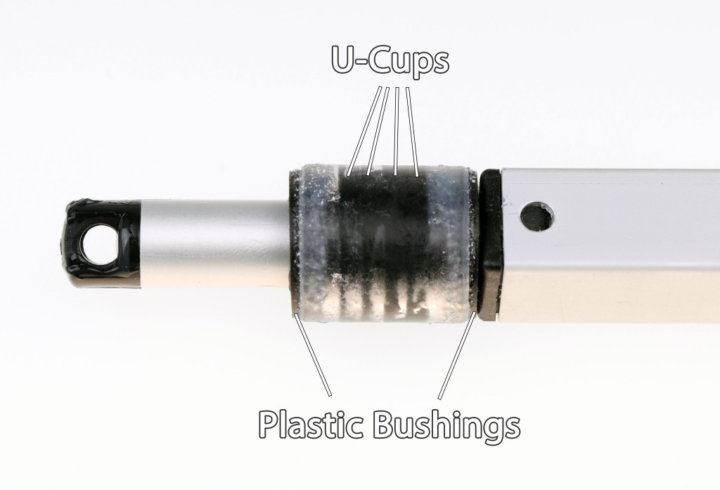
![]()
The u-cups are inserted into the tube. Plastic bushings keep the rod and tube concentric.
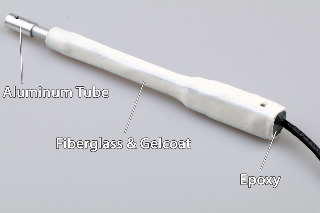
![]()
The actuator is further reinforced by a fiberglass sleeve which also makes the body completely waterproof. The plastic end of the rod on the original actuator looks like a weak point, so I glued a piece of aluminum tube over it.
-
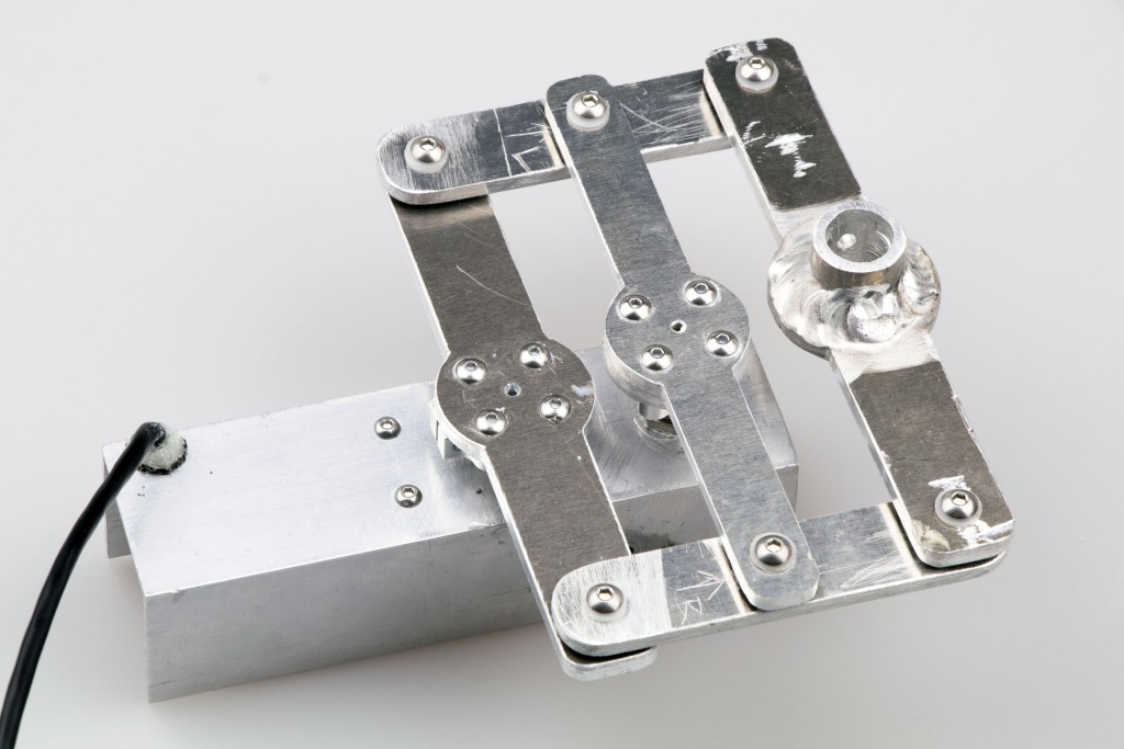
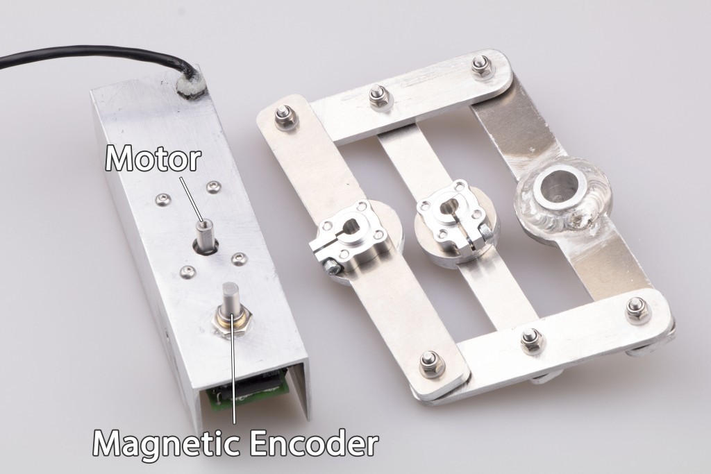
Rudder Control
05/09/2018 at 07:18 • 0 commentsThe rudder will be driven by a worm geared brushless motor mechanically coupled to a rotary magnetic encoder that provides an absolute position feedback. A while ago, I was testing this setup and shared my results in this project log. Now I have put together a metal "servo" that can be easily connected to the rudder shaft.
![]()
![]()
![]()
Updated source code:
OpenTransat
Building an Autonomous Sailboat That Pursues to Cross the Atlantic Ocean