Andy Osusky
-
More carbon fiber parts
04/25/2018 at 06:36 • 0 commentsThe boat consists of 6 carbon fiber parts: two for the hull, two for the sailwing and two for the keel. All parts were made by resin infusion just like the hull as seen in the video from the previous log.
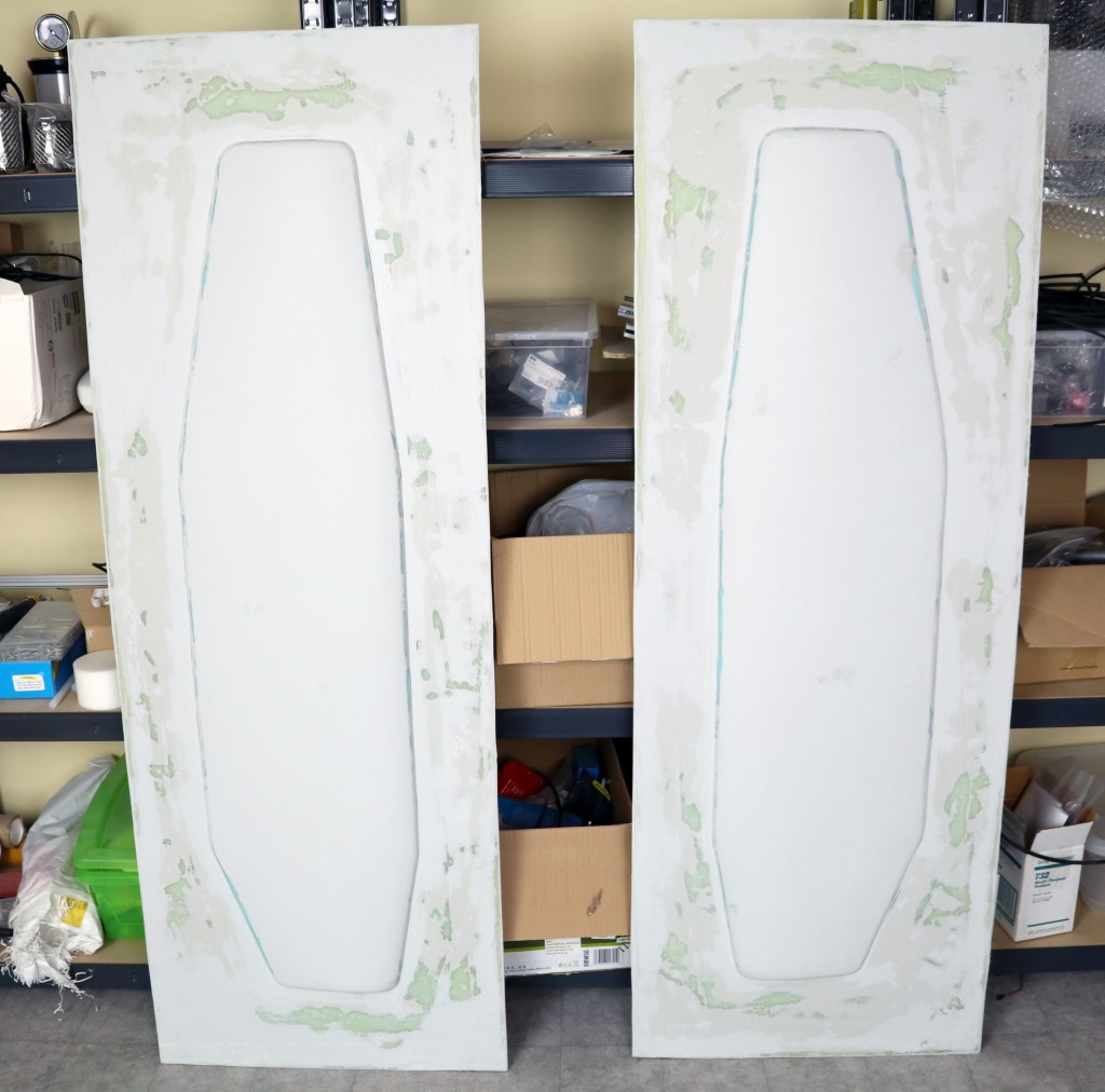
The sailwing
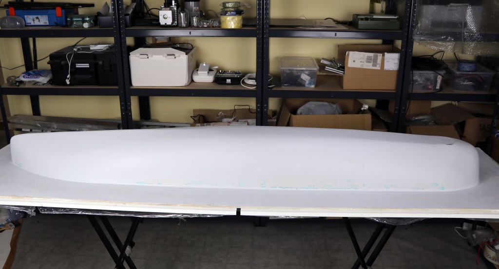
Plugs:
![]()
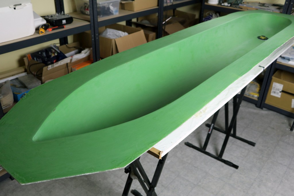
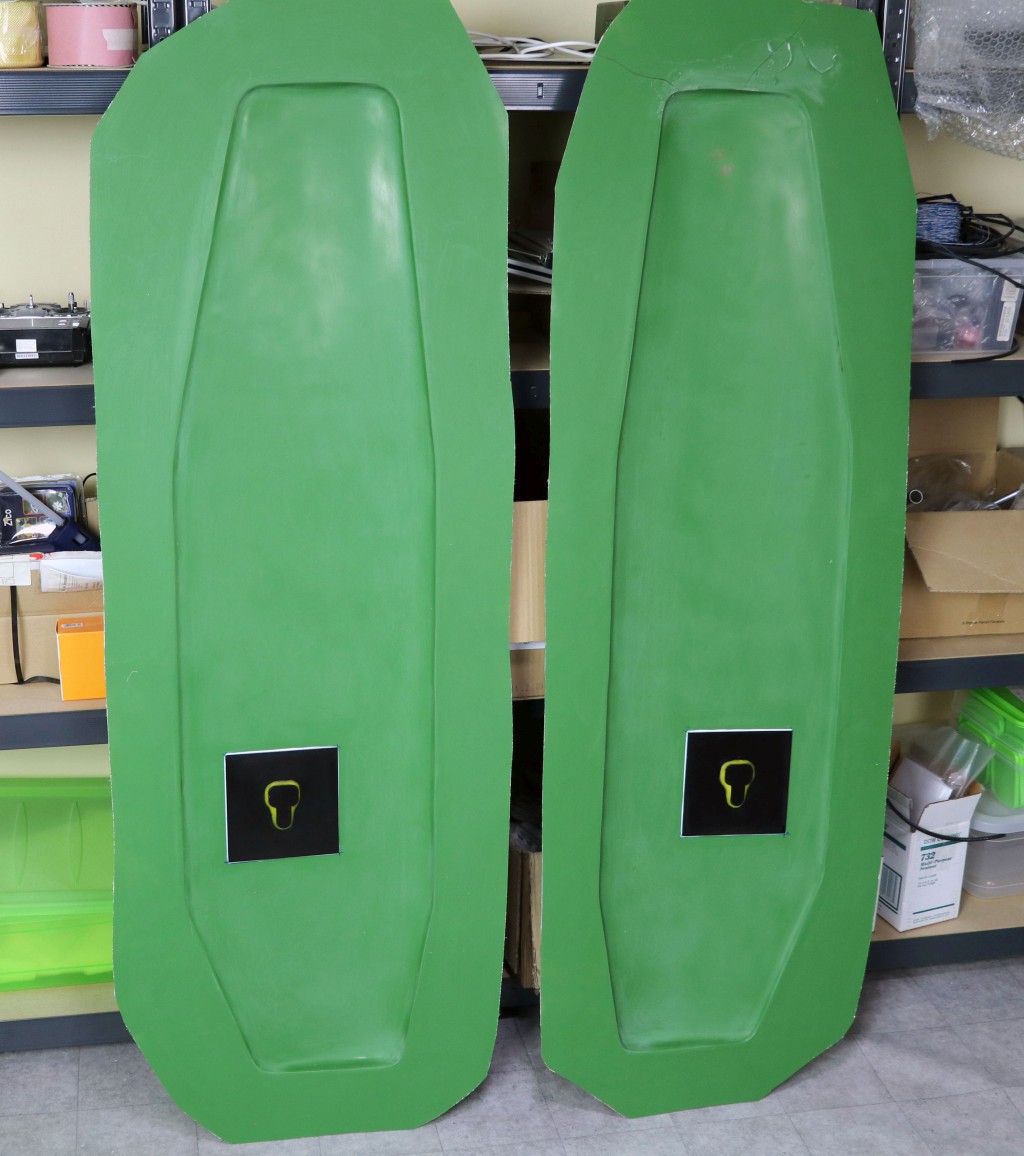
Molds:
![]()
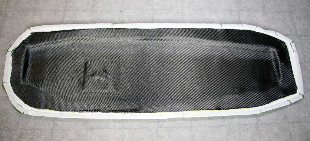
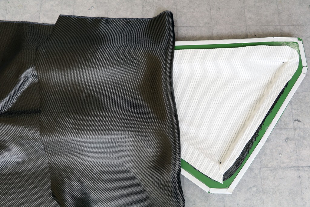
Laying up fabric: 80gsm fiberglass, 200gsm Kevlar and 3x 200gsm carbon fiber
![]()
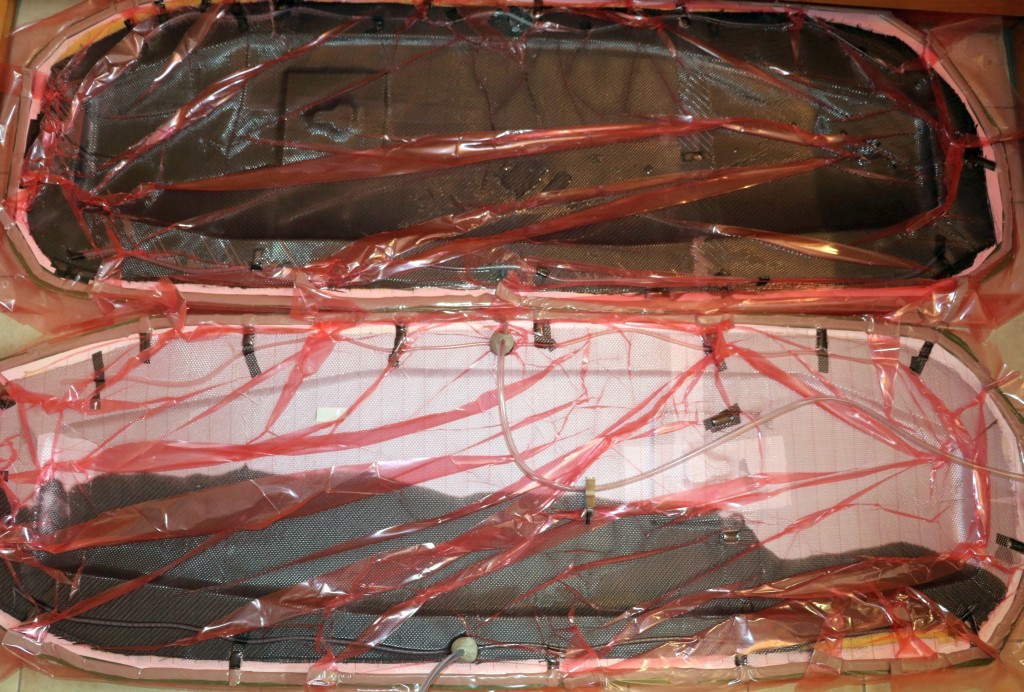
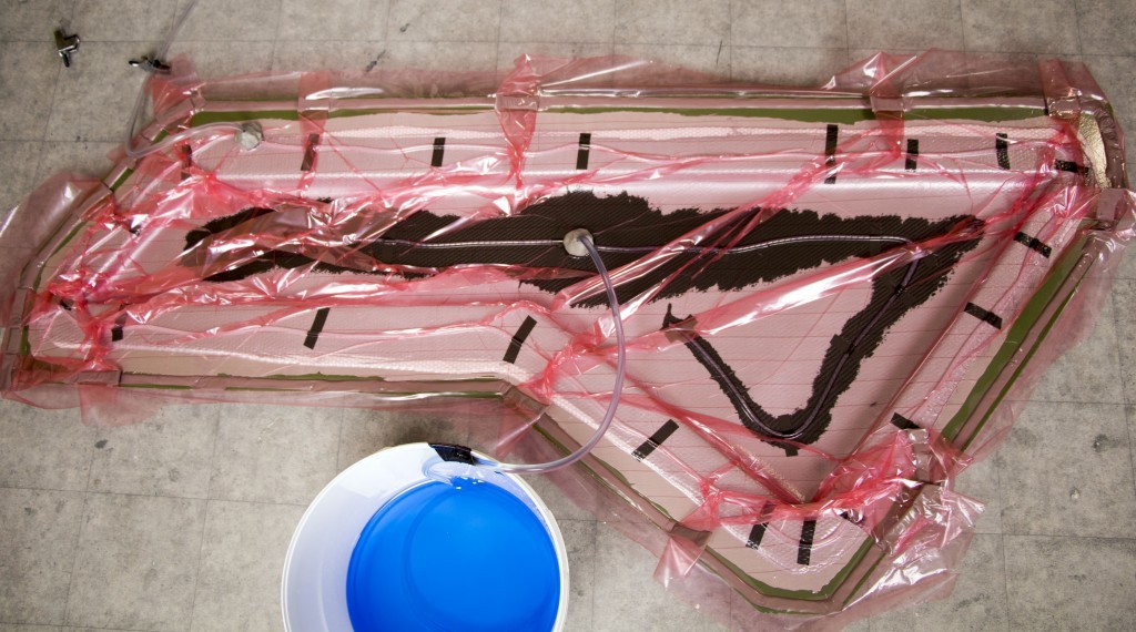
Resin infusion:
![]()
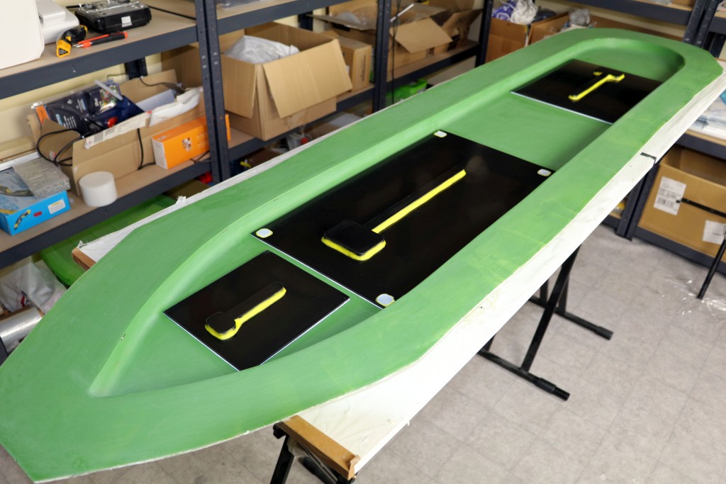
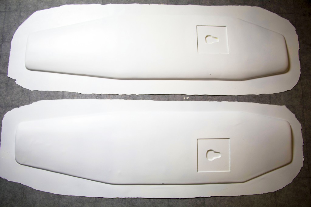
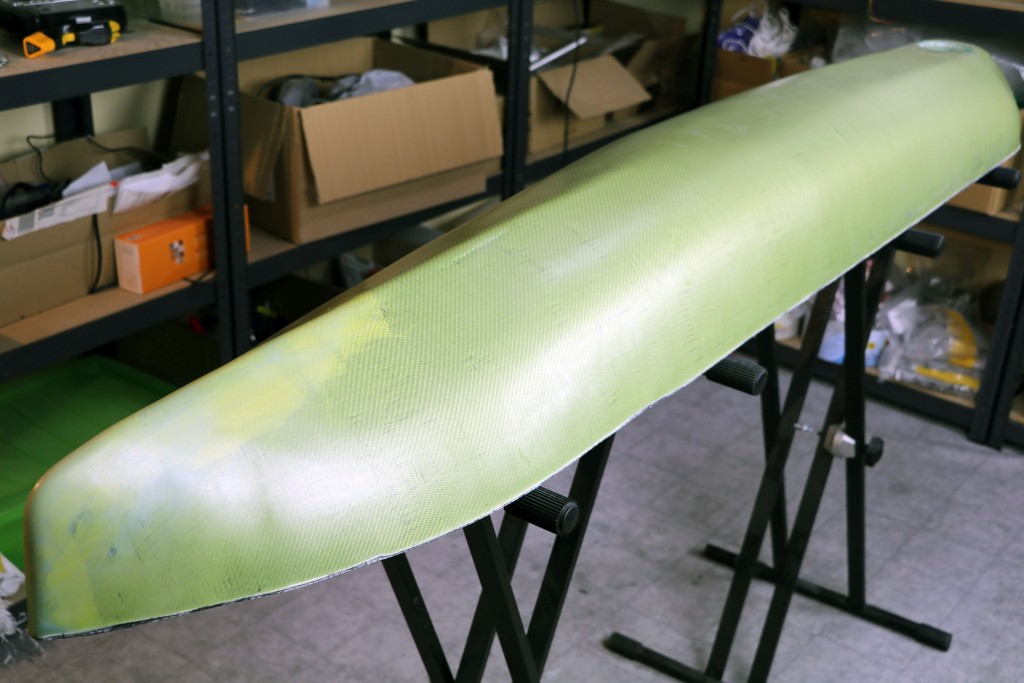
The parts released from the molds:
![]()
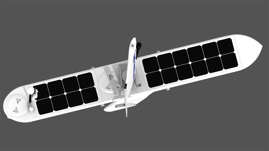
The rectangular cavities you see on both sides of the sailwing will be fitted with small solar panels that will provide power for the actuator.
The keel
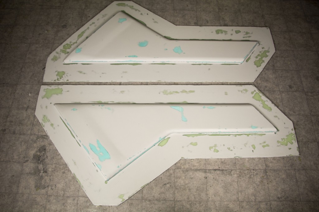
Plugs:
![]()
Molds:
![]()
Laying up fabric: 200gsm fiberglass, 200gsm Kevlar, 2x 200gsm carbon fiber, foam core (2mm Lantor Soric) and 2x 200gsm carbon fiber
![]()
Resin infusion:
![]()
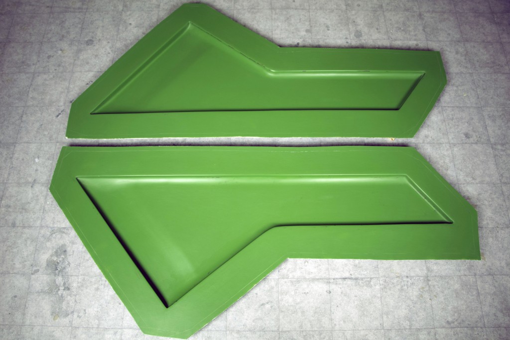
The finished parts:
![]()
-
The finished carbon fiber hull
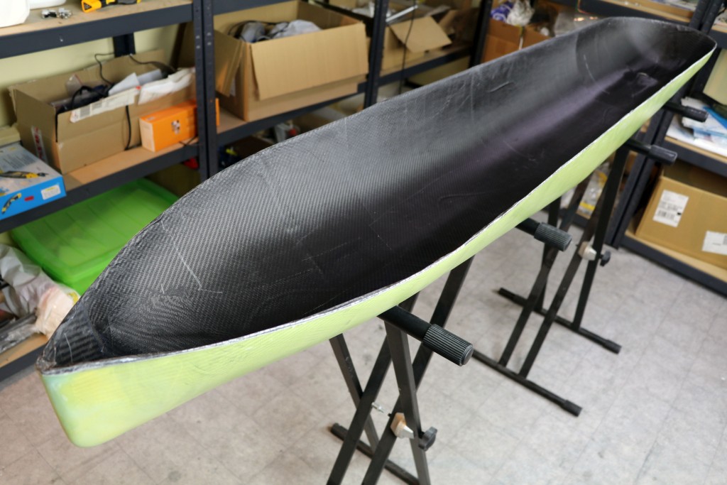
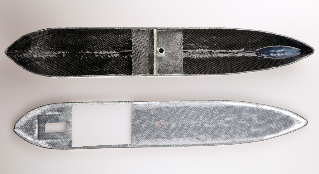
03/28/2018 at 07:26 • 0 commentsThe hull was built from carbon fiber, Kevlar and a foam core. In the video below, you can see the whole process from laying up the fabric to resin infusion.
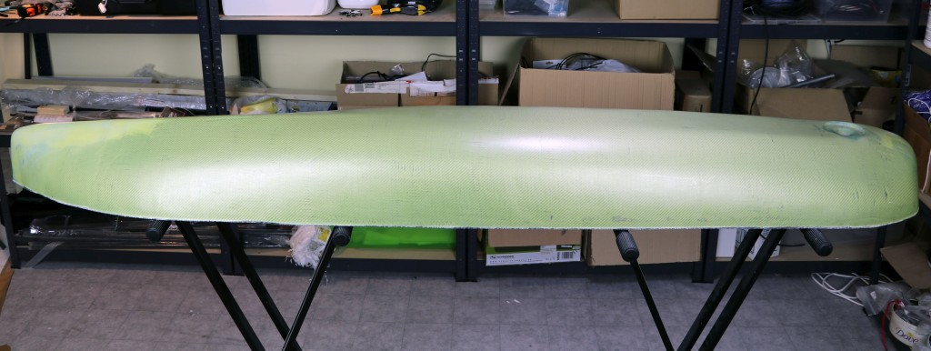
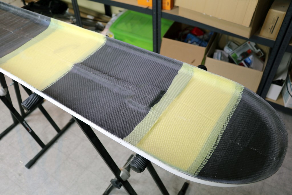
Bottom part (hull)![]() The yellow outer layer is Kevlar. It protects the carbon fiber hull from impacts and abrasion.
The yellow outer layer is Kevlar. It protects the carbon fiber hull from impacts and abrasion.![]()
![]()
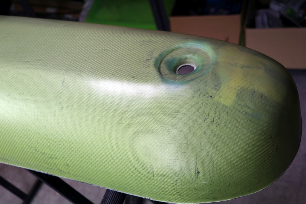
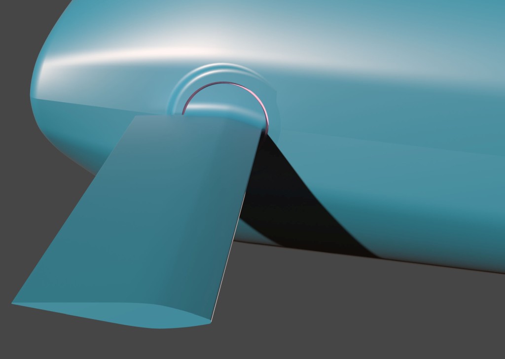
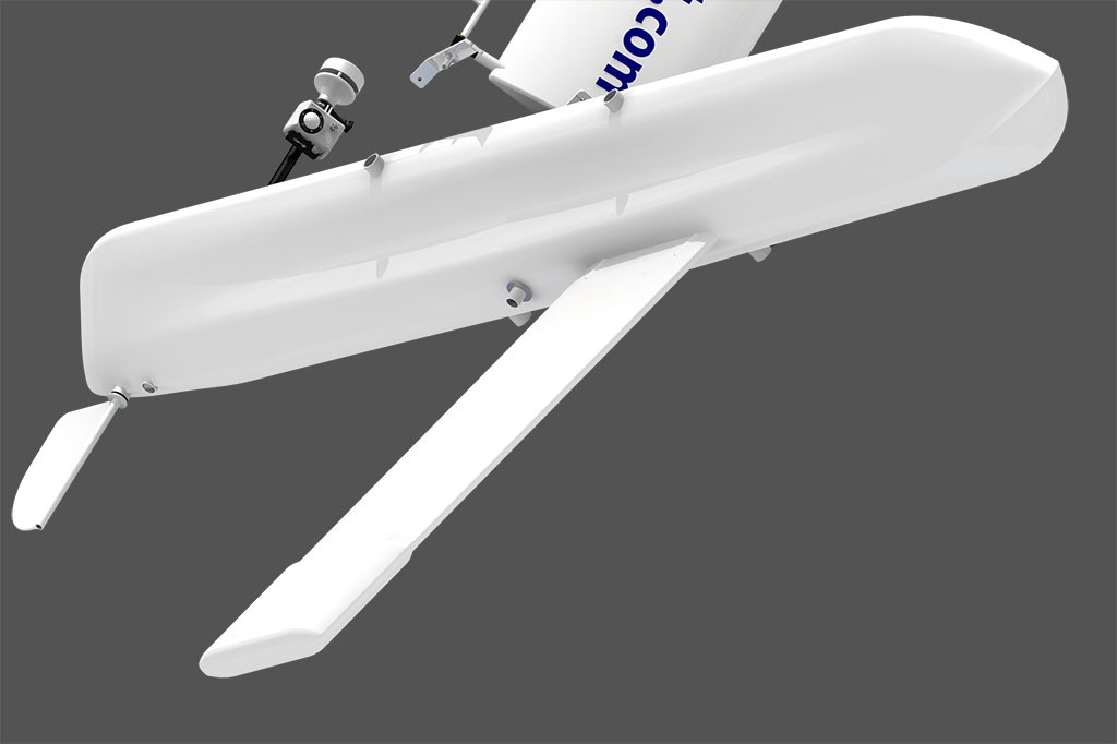
The rudder is designed with a flange that will fit this cavity in order to prevent entanglement around the rudder axis. This cavity was made in the same way as the cavities for solar panels on the deck (see the previous project log).
![]()
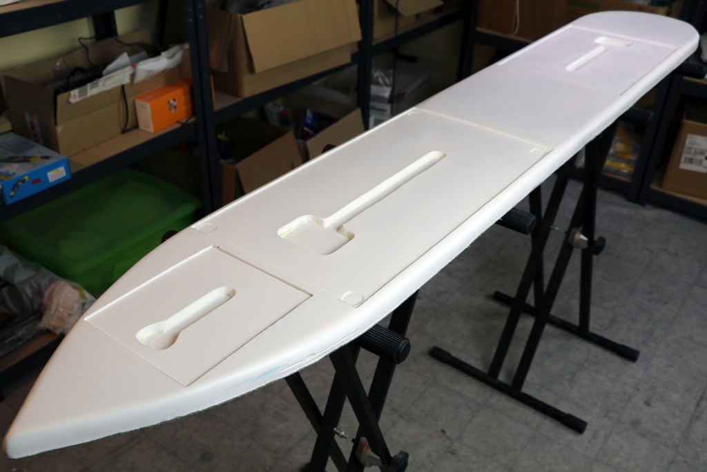
Top part (deck)
![]()
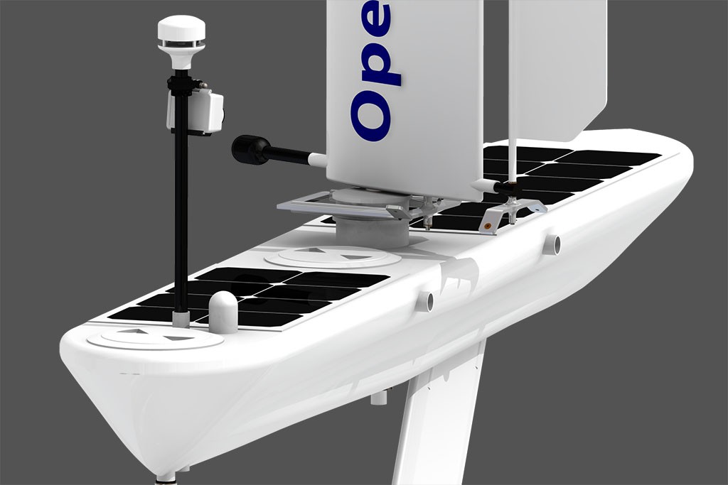
These cavities on the deck will fit solar panels with connectors and cables, making the boat hull streamlined.
![]()
Because carbon fiber partially blocks GPS signal and satellite Internet connection, it's replaced with fiberglass and Kevlar in some areas of the deck. With this little trick, communication modules can be placed under the deck.
-
The molds are ready!
03/12/2018 at 07:51 • 0 commentsCheck out a video how the molds were built from the plugs:
Bottom part mold (hull)
![]()
Top part mold (deck)
![]()
Now it's time to build strong carbon/Kevlar parts using resin infusion.
-
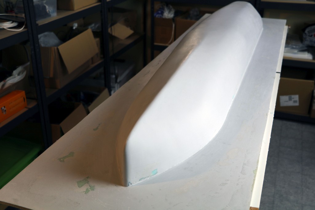
Finished plugs!
03/01/2018 at 08:44 • 0 commentsCheck out a video how the foam plugs were built:
Bottom part (hull)
![]()
![]()
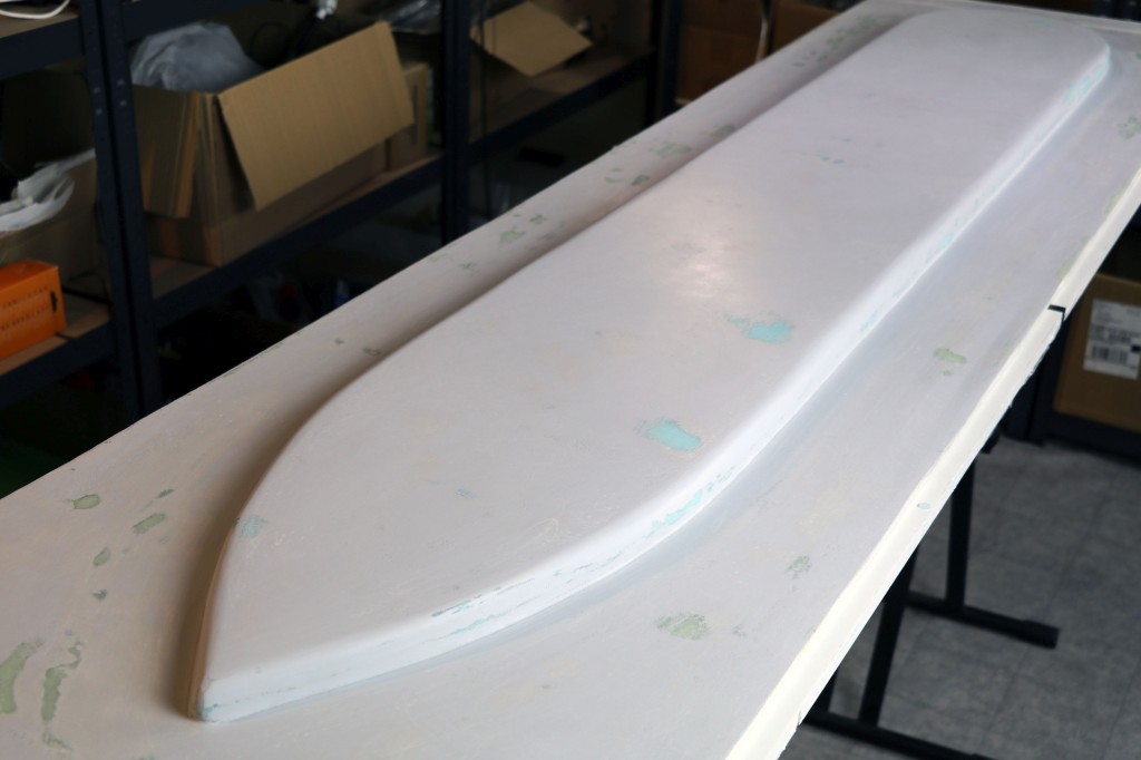
Top part (deck)
![]()
The next step is building the molds.
-
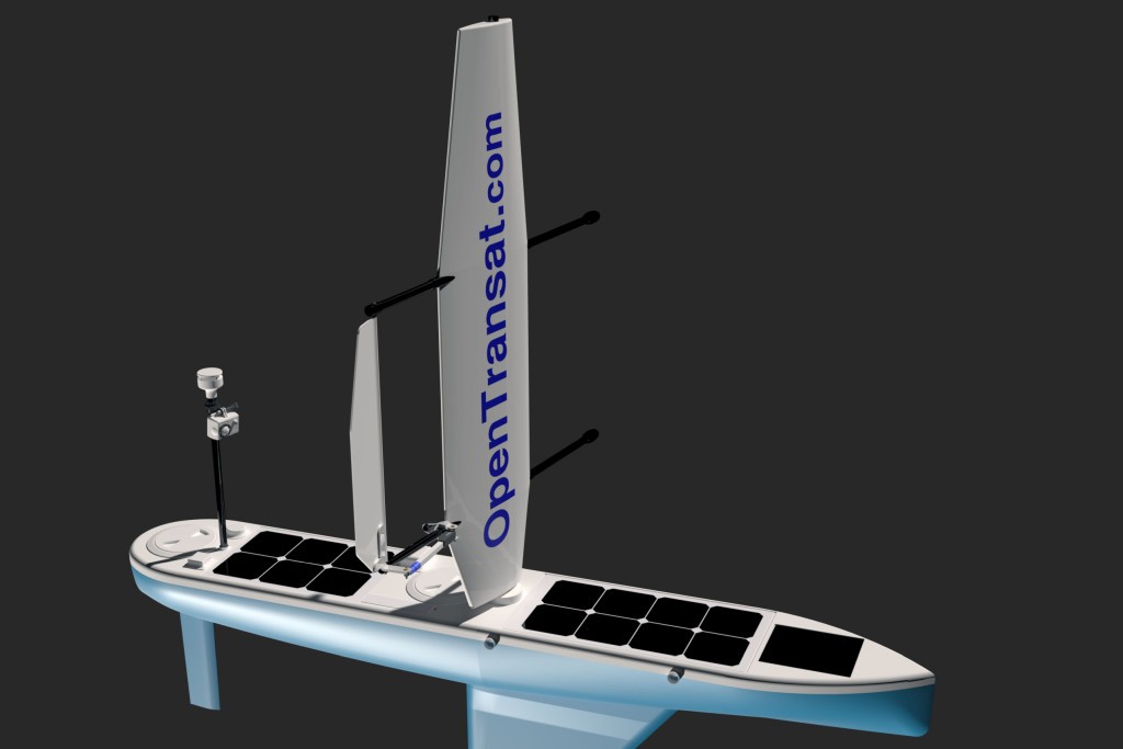
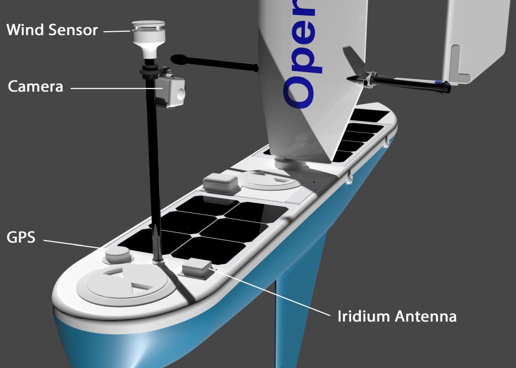
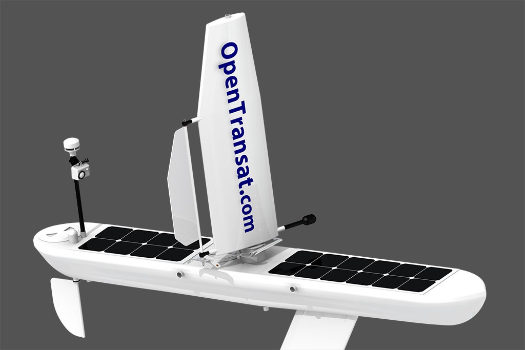
Final 3D Design
12/05/2017 at 10:30 • 1 commentThe design posted back in 2016 has now been improved in many aspects. It's more streamlined, balanced, robust and optimized for speed.
![]()
![]()
![]()
![]()
![]()
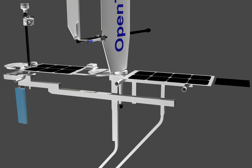
This rudder combines two interesting features – avoids entanglement and reduces the power needed to steer the boat.
Here's how it's designed on the inside. The heavy duty aluminum skeleton holds all the critical parts together.
![]()
From this point, it's going to be pretty straightforward. The next step is to make a foam hull using a CNC foam cutter and then build the molds.
-
Successful Lake Test
11/06/2017 at 13:28 • 0 commentsThe small-scale model from the previous log has been tested on a lake. Wow, this wingsail concept works incredibly well!
-
Small-Scale Prototype
10/16/2017 at 11:47 • 0 commentsA small-scale prototype of the boat has been built to test and tweak the concept before spending a lot more time building the bigger boat for extreme ocean conditions. It's a close copy of the final design with the same hardware and navigation software. Here's the build progress.
Carbon Fiber Hull
![]()
Different techniques were evaluated to build these two carbon fiber parts. I will give more details when building the ocean-going boat.
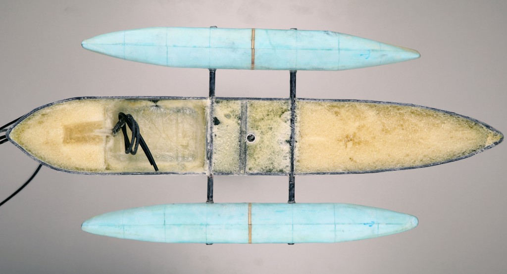
Filling with Foam
![]()
The hull has been filled with a closed-cell polyurethane foam. The side floats were made from XPS foam wrapped with fiberglass.
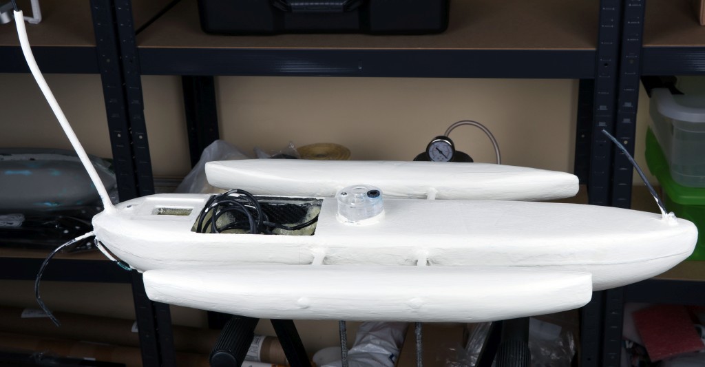
Joining and Painting
![]()
The two parts of the hull were joined using a Kevlar tape and painted with a special antifouling paint. This kind of paint doesn't give as smooth finish as a gelcoat or normal paint, but it prevents subaquatic organisms from attaching to the hull.
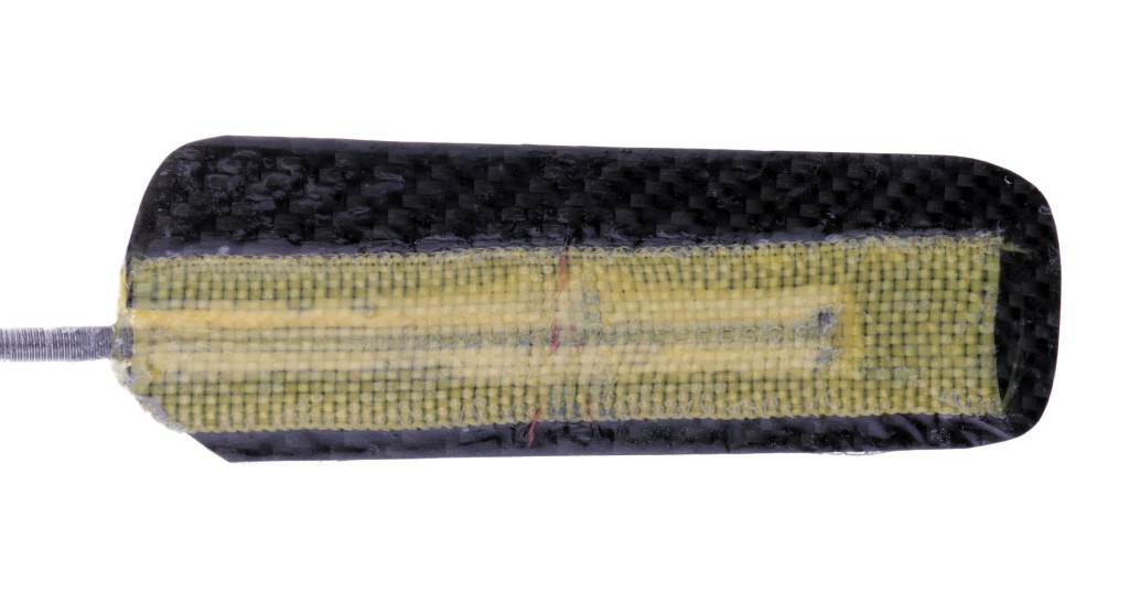
Rudder
![]()
The rudder is made from carbon fiber, Kevlar and a steel rod.
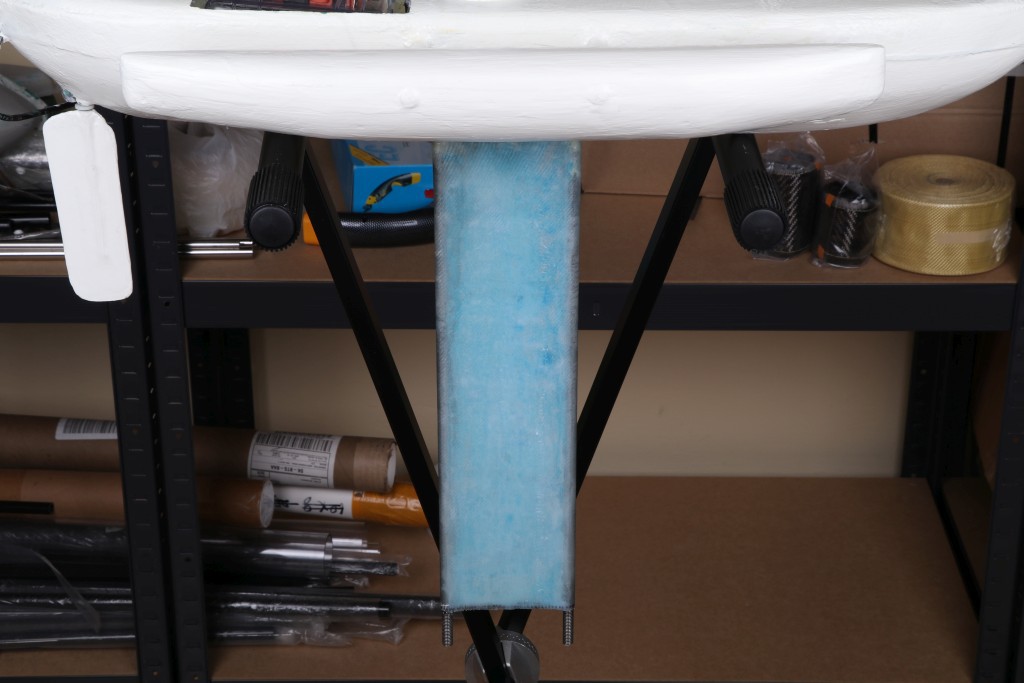
Keel
![]()
The keel is made from two threaded rods and a foam wrapped with fiberglass. Finally, the foam was dissolved with acetone to decrease buoyancy.
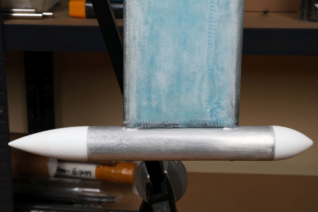
Bulb
![]()
The “bulb” is made from aluminum tube filled with lead and two 3D-printed plastic parts.
Servo, GPS, Electronics Housing
![]()
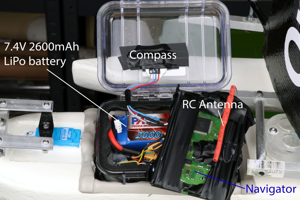
Electronics
![]()
The battery provides enough power for 8 hours of continuous operation.
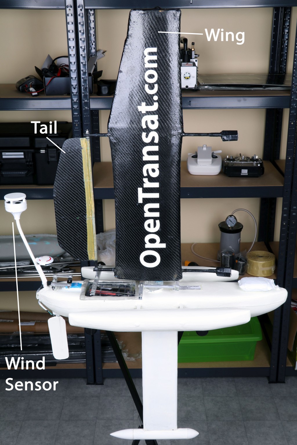
Wingsail
![]()
The wingsail is made from a foam wrapped with carbon fiber. This kind of sail works much like an airplane wing – it automatically maintains an effective angle of attack using the small "tail" behind the large wing. This concept is inspired by experimental work found on www.sailwings.net.
Finished Boat
![]()
-
Testing, Testing
10/05/2017 at 11:03 • 0 commentsEvery single component of the boat is thoroughly tested before implemented in the design. Here I will talk about the most important recent results.
PID Controller Testing
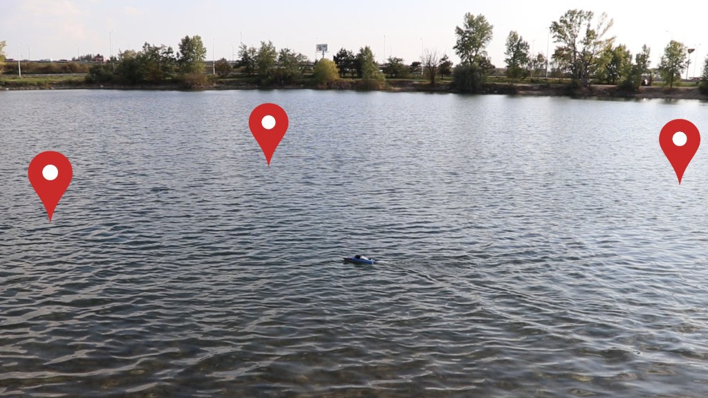
PID controller is a computer algorithm that takes into account immediate compass and position changes while steering, so the boat keeps its heading in a straight line.
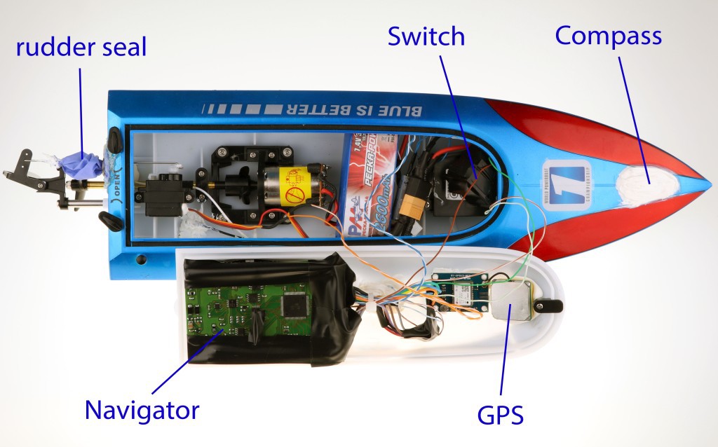
https://en.wikipedia.org/wiki/PID_controllerStability at high speeds would be difficult to test with a sailboat as the winds in the middle of the ocean can be much stronger. Therefore, a hobby RC boat has been converted to autonomous boat to fine-tune the PID controller working at high speeds.
![]()
![]()
Servo Testing
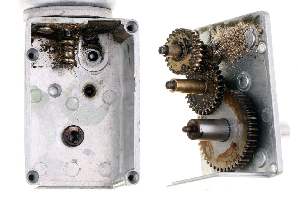
The most common issue in the previous transatlantic attempts is rudder failure. If we expect a rudder moving every 3 seconds for a duration of 6 months, this makes over 2.5 million cycles! That's more than any servo manufacturer can guarantee (besides some very special and expensive products for medical applications).
I have been testing a cheap worm drive sold as JGY-2838 connected to a magnetic encoder EMS22A as seen in the video below.
It's loaded with weight to simulate water resistance. The motor made over 3 million cycles under decent load until it failed. You can see in the picture that the worm gear is completely worn off.
![]()
It's not bad – it means about 7-9 months of continuous operation in the ocean which is more than the expected time frame (less than 3 months). There are two ways to improve it even further without much additional work:
- Add extra lubricant into the gearbox. Experts say that the worm won't wear off as long as it's properly lubricated. It starts to wear off very quickly after the lubrication fails.
- Steer less frequently. If the boat corrects its heading every 5-10 seconds on average, it can function for over an year or two.
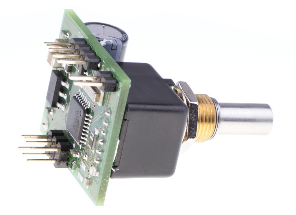
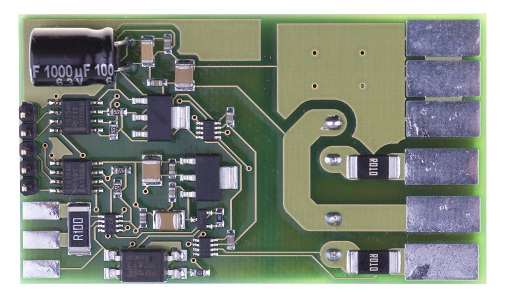
The motor will be controlled by a separate Arduino-like PCB connected to the encoder:
![]()
Source code:
https://github.com/OpenTransat/ServoEncoder
Hatch Testing
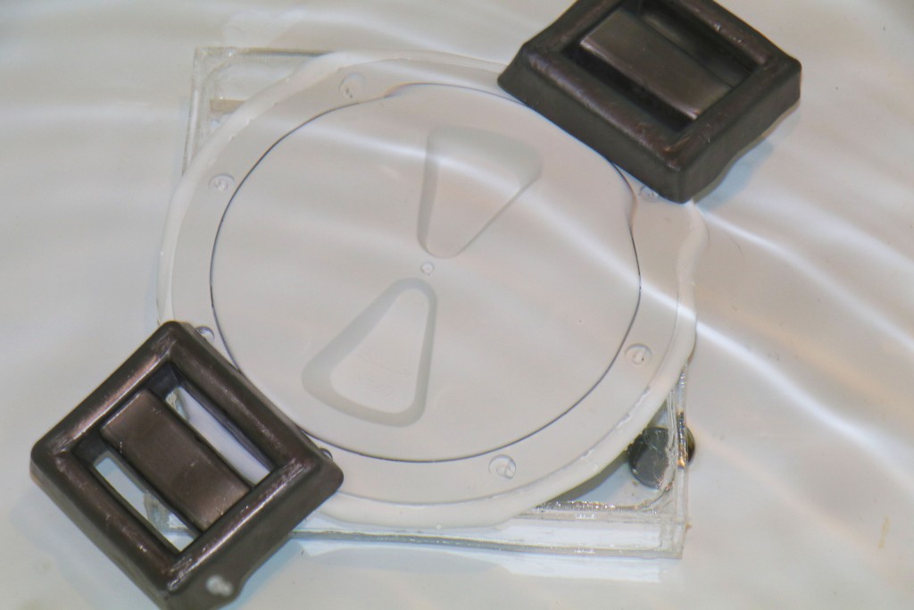
The hatch can be opened in order to access the electronics and it has to be perfectly watertight. The hatch in the picture is from a yacht shop and has been mounted on acrylic “aquarium” for testing. It was left underwater for 7 days and there was not a single drop of water inside the aquarium.
![]()
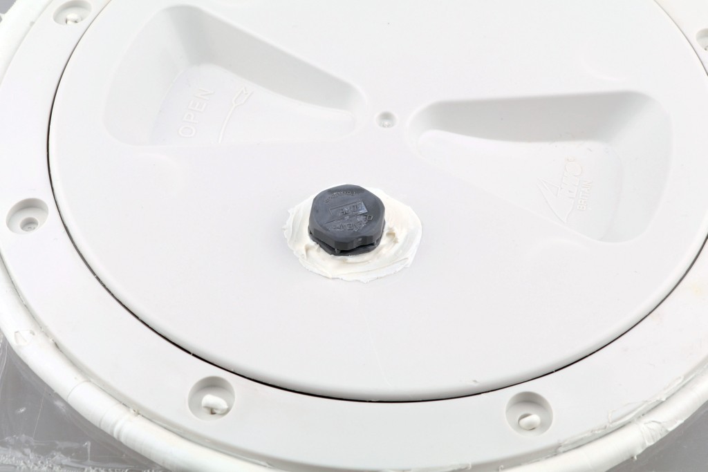
To compensate the air pressure inside the hull (remember that the air expands during hot days and contracts when it cools down at night), a Gore membrane vent has been fitted on the hatch. The Gore vent is a little magic that allows air to pass through the membrane, but it doesn't let any water in. Again, it has been tested underwater for a week.
![]()
-
Boat Controller
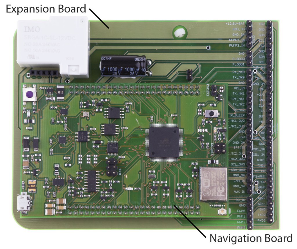
06/07/2017 at 13:37 • 0 commentsThe new boat controller consists of two PCBs – the Navigator mounted on top of the Expansion Board.
![]()
The Navigator will be responsible for the most important tasks like navigation, collision avoidance and sending messages. The Expansion Board that will provide additional functions more specific to the boat. This modular design allows to make quick modifications on the Expansion Board while keeping the more complex Navigation Board unchanged.
Here are all features of the boat controller:
- The microcontroller is Atmega2560 running at 16 MHz. It has been chosen because it's widely used in development boards like Arduino Mega and there's a vast amount of available libraries for various sensors.
- It can be programmed over Wifi. This will make life easier as there is no need to open the hatch and connect the cable for programming. The boat can be tested in the ocean while staying connected to a laptop located on the shore or motorboat. With a long range Wifi antenna, the program can be uploaded even hundreds of meters over the air.
- Tilt compensated compass. There will be also an auxiliary compass that will be mounted far enough from magnetic noise.
- Accelerometer & gyro. The motion sensor will give us a better idea about what the boat is actually doing, especially during storms and high winds. It will report pitch & roll, average wave height, etc.
- Battery power sensor.
- 2 MB flash memory for data logging.
- Experimental 256 KB FRAM memory which is faster than flash.
- Temperature, pressure and humidity sensor. It may discover potential problems inside the waterproof housing such as leaking, overheating or need for pressure compensation.
- Watchdog timer based on a low-power microcontroller that monitors the “heartbeat” of the main CPU. If the Navigator doesn't respond for a minute or it reports any kind of failure, the watchdog will cut power for a few seconds. This is how we usually fix problems. :)
- A couple of MOSFET switches to turn on particular hardware only when needed: Linux computer with a camera, satellite modem, AIS receiver (for collision avoidance), RC receiver and water pumps. Wondering what the water pumps are for? They will pump water out of the boat if flood sensors detect big trouble...
Power Sensor
There will be one additional board that will measure voltage and current of each solar panel separately. It will be interesting to see which panel is shaded by the sail at any particular time.
![]()
Complete hardware scheme:
![]()
The source is published on GitHub:
-
New Design
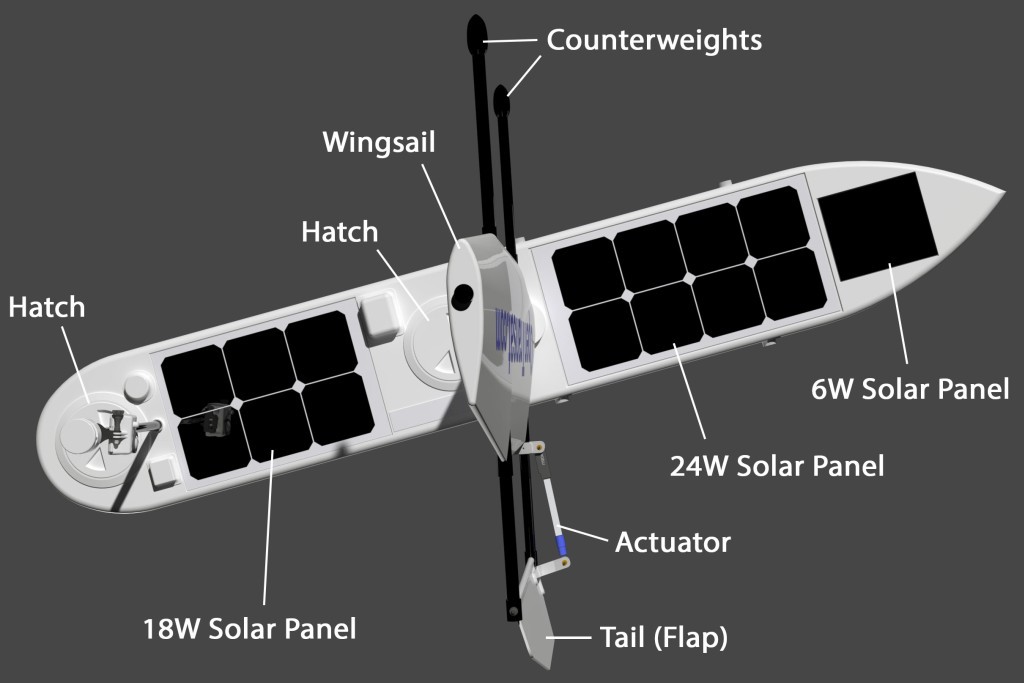
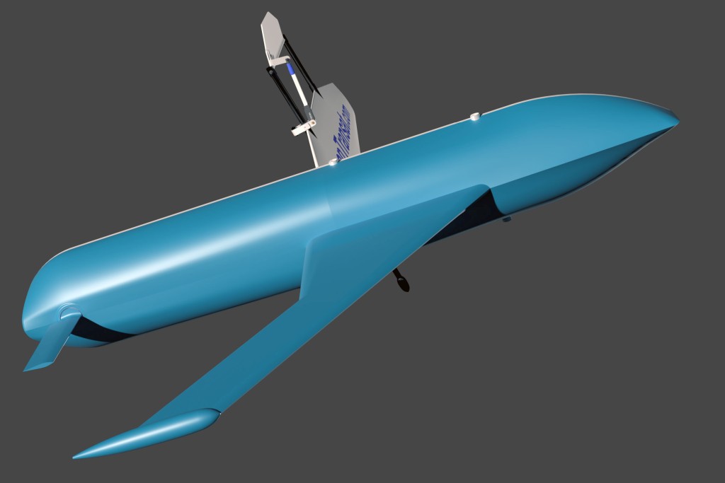
11/22/2016 at 10:05 • 0 commentsBelow is the design of the new autonomous boat that will attempt to cross the Atlantic. It will be built from carbon fiber, fiberglass and Kevlar. The total length will be 2.2 metres (7.2 feet). The long and narrow hull is optimized for speed. Instead of a typical sail, there is a rigid wingsail as seen on modern yachts.
![]()
![]()
![]()
![]()
First, I am going to build a miniaturized version to test the hardware and software. I will keep you updated on the progress!
OpenTransat
Building an Autonomous Sailboat That Pursues to Cross the Atlantic Ocean

 The yellow outer layer is Kevlar. It protects the carbon fiber hull from impacts and abrasion.