Close
0%
0%

Wi-fi Controlled FPV Rover Robot

This project shows how to design a wi-fi remotely controlled two-wheeled robotic rover, using an Arduino Uno and an ESP8266.

Similar projects worth following
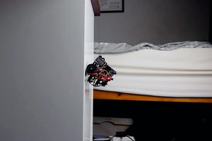
This project shows how to design a remotely controlled two-wheeled robotic rover over a wi-fi network, using an Arduino Uno connected to an ESP8266 Wi-fi module and two stepper motors. The robot can be controlled from an ordinary internet browser, using a HTML designed interface. An Android smartphone is used to broadcast video and audio from the robot to operator's control interface.

There is a lot of robotic kits available online with various shapes, dimensions and prices. But, depending on your application, none of them will fit, and you might find out they are too expensive for your experiments. Or maybe you just want to make your your mechanical structure instead of buying a complete one.This tutorial also shows how to design and build a low-cost acrylic frame for your own robotic project, using just ordinary tools for those who doesn't have access to those expensive 3D printers or laser cutters. A simple robotic platform is presented here.

To build a custom robot, first you'll have to design your mechanical structure. It might be easy, depending on your application, or full of details and constraints. You might need to design it in a 3D CAD software or just draw it in 2D, depending on the complexity of your model.

You might also buy the complete structure online if you doesn't want to build your own mechanical structure. There is a lot of robotic kits available online. In this case, you might jump to Step 6.

For this project, a low-cost acrylic frame was designed for the attachment of the motors and other components. The structure presented in this tutorial was 3D designed using 123D Design CAD software. Each part was later converted in 2D using Draftsight software.

base.dwg

2D model of the base plate

DWG Drawing - 155.13 kB - 09/30/2016 at 23:41

Download

robot.123dx

123D Design 3d model of the robot

123dx - 400.83 kB - 09/30/2016 at 23:40

Download

wistepper.ino

Arduino code

ino - 2.82 kB - 09/30/2016 at 23:40

Download

wistepper - rev1_Esquemático.pdf

Circuit schematic

Adobe Portable Document Format - 1.01 MB - 10/15/2016 at 15:40

Preview

wistepper - rev1_bb.pdf

Breadboard connections

Adobe Portable Document Format - 1.08 MB - 10/15/2016 at 15:40

Preview

View all 7 files

View all 20 components

  • 1
    Step 1

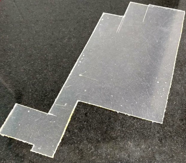
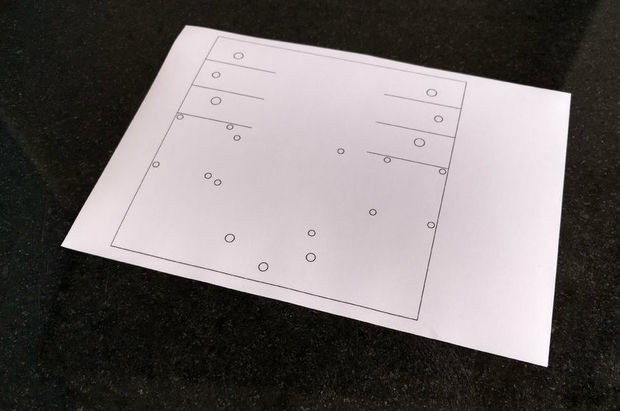
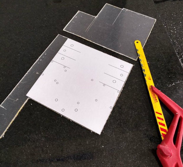
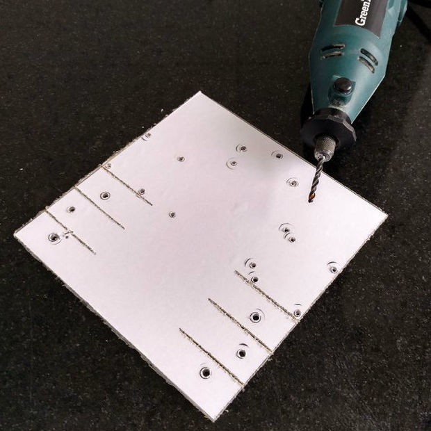
    First you'll need to transfer the dimensions of your model to the acrylic sheet. Print your 2D drawing using an ordinary printer on an adhesive paper, then cut the paper in suitable dimensions and apply that mask on the surface of the acrylic.

    You might use a hand saw to cut the acrylic according to your dimensions or use break technic described bellow.

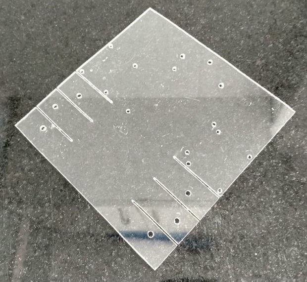
    With an utility knife and with the help of a ruler or a scale, cut the acrylic in straight lines. You won't need to cut all the way thru the sheet, just score it to create some tracks where the piece will be later cutted.

    Place the acrylic on a flat surface, hold it in place with some clamps and apply some pressure until the sheet breaks into two. Repeat this process untill all the cuts are done. After that, you might use a sandpaper to smooth rough edges.

  • 2
    Step 2

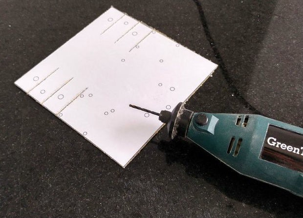
    Drill the holes in the positions in shown in the 2D drawing (indicated in the mask) with a drilling machine.

    Acrylic is relativelly easy to drill. So if you don't dispose of a drilling machine, you can drill the holes manually with a sharp tool, like an utility knife. You might also use it to enlarge small holes to fit bolts sizes.

    Remove the mask and your base will be ready.

  • 3
    Step 3

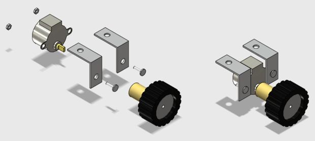
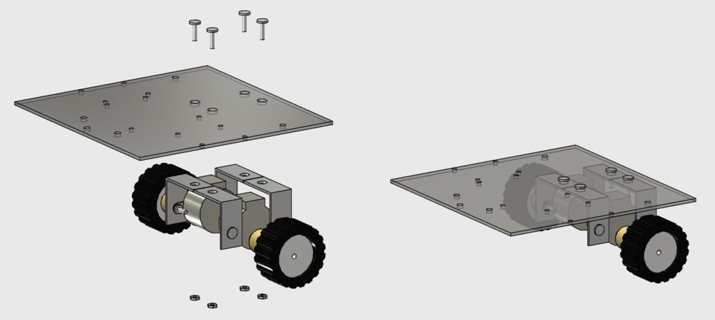
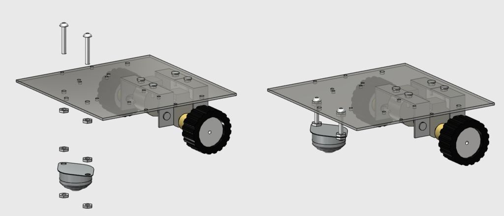
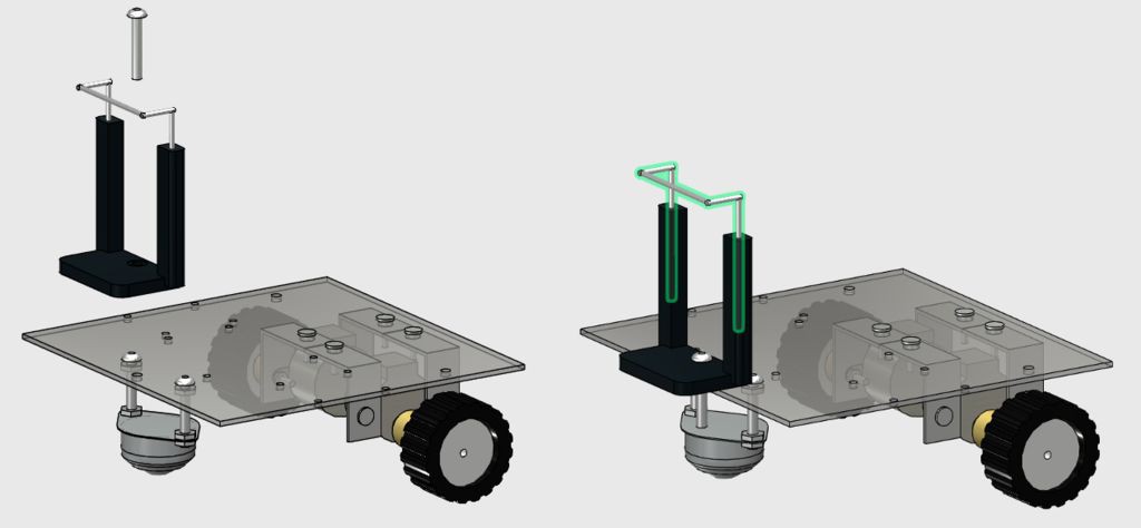
    Mount the components with bolts and nuts according to the images, and your structure will be ready to go.

    M3 bolts are used for the instalation of the stepper motors, while the 5/32" ones are used for the instalation of the front wheel and the smartphone clip.

    Now take a break and start to assamble the circuit in the following step...

View all 9 instructions

Enjoy this project?

Share

Discussions

Similar Projects

Does this project spark your interest?

Become a member to follow this project and never miss any updates