Compiling the code for the first sensor board with a test code sketch occupied 98% of the available flash. A similar sketch on the new Arm design uses only 10%. Awesome...
Only one revision manufactured by OSH Park has been created so far. It has a few issues that will be fixed on the next version.
- add + and - silkscreen to the pads on the lipo battery so you know the polarity
- add a stronger LDO, the CAT6219-330TDGT3
- all tracks should be thicker then 6 or 7 mil
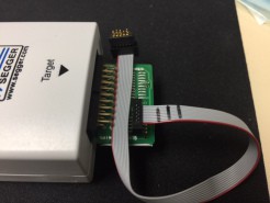
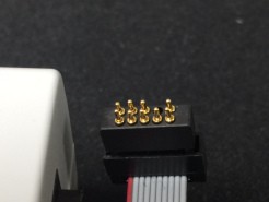
- remove pin 7 on H3, this will mark the polarity for burning the bootloader using the Segger J-link
- three seperate leds are necessary, right now D13 only lights when connected to USB, D13 one end to +3.3V
- flex cable on oled is tight, slot or board notch possibly needed
Video of it in action running test code to verify the hardware components are properly soldered.
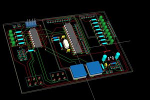
It's pretty tiny so a 4 layer board made the whole job easier. The top and bottom are pretty much dedicated for components, layer1 are tracks and power traces, layer2 is a ground plane. Mixing up an internal plane and routing layer was interesting.
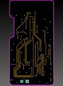
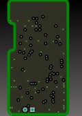
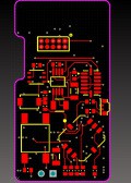
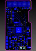
The schematic, gerbers, Altium Files and BOM are all available here
The OSH Park board has been shared out here
Installing the bootloader was just as easy as using a USBtinyISP as you would on a 328P or 32u4 processor using the Arduino IDE. Just follow these instructions here
Hardware needed from Digi-Key are: Segger J-link, Digi-Key #899-1008-ND and 899-1012-ND. My board uses tiny 50mil pads that you press mini pogo pins on. Mill-Max part number 855-22-010-10-001101 makes the perfect solution. Just plug this 5x2 pogo pin connector into the end of your cable. I removed one of the 10 pogo pins and will do the same on the next revision so the polarity will always be correct. The tiny 5x2 pads that the pogo pins press onto are located under the oled glass on the Top Layer shown above in red.
Thanks to Adafruit for providing the bootloader and libraries for most of the components. Without them, this project would not exist.
 0miker0
 Abid Jamal
 Colin McAllister
 Pallav Aggarwal
 Michael O'Toole