-
Beeper upgrade
03/23/2017 at 18:31 • 2 commentsThe system has been running through the winter just fine, so when it comes to dealing with the elements I'm happy with the prototype. What I've not been happy with is the sound level. It was not really loud out of the enclosure, but once in the enclosure it's really pathetic even if you're right by it. It needed an upgrade.
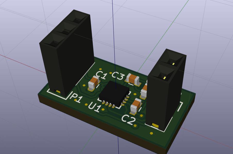
So I made a little board based on the Diodes Inc PAM8904, which is a piezo driver with built-in charge pump that bumps my little 3Vpp signal to 18Vpp.
![]()
The board is shared on OSH Park.
You just need to add the PAM8904 and 4x 0.1 uF capacitors. The 2-pin header connects to the piezo beeper, and the other connector has GND (pin 1), signal (pin 2) and 3V (pin 3).
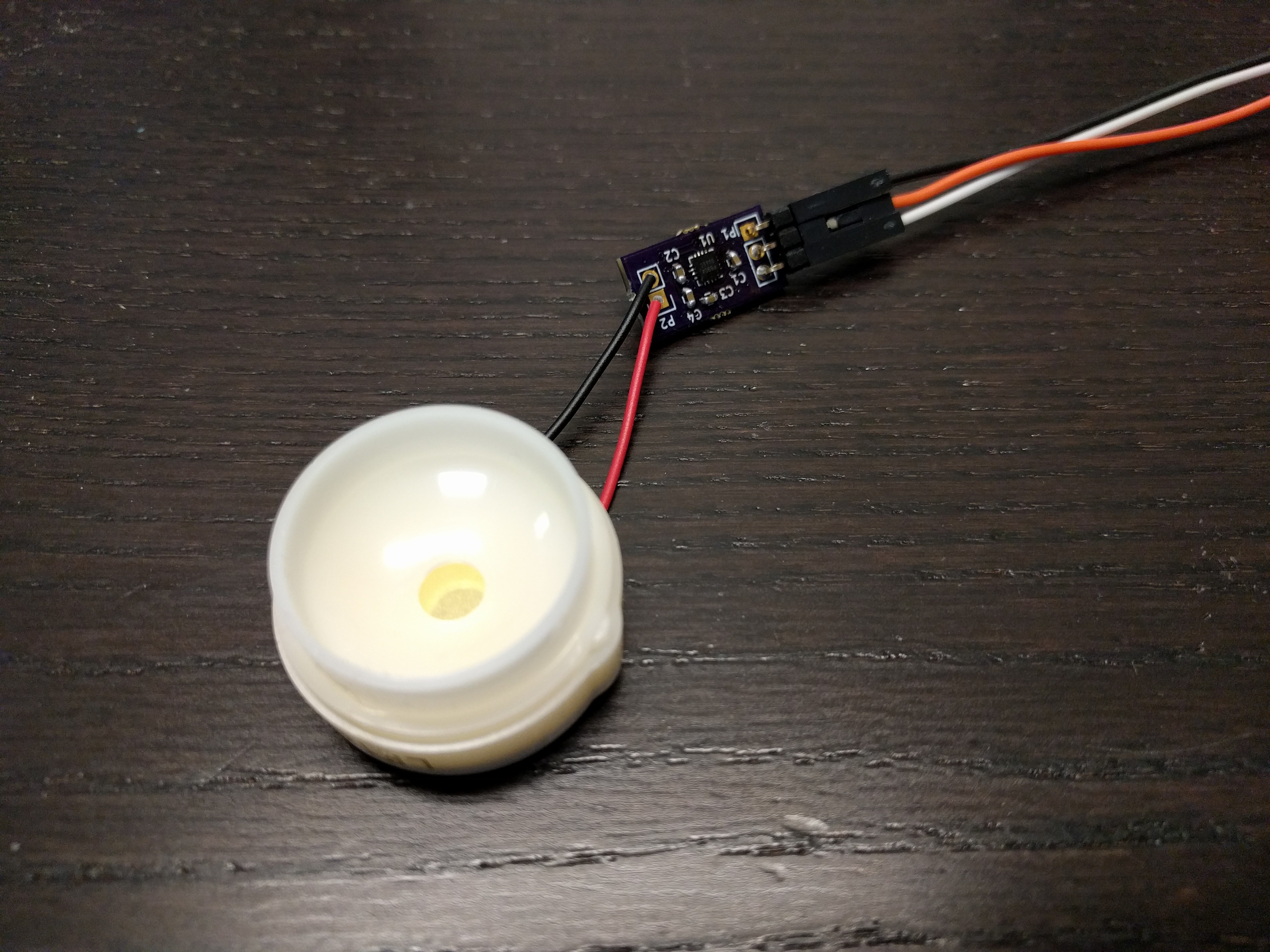
I finally built up a prototype today, and I can confirm that it is LOUD. :) Hopefully it will be audible in the enclosure now.
![]()
-
Prototype performance
10/02/2016 at 23:00 • 0 commentsWell, the good news is that it works. :) Mounted to a south-facing fence, the battery stays charged very well, varying between 3.2V in the morning and 3.4V in the sun:
![]()
I've now moved it to a north-facing fence post. That will be a much more interesting test. :)
The bad news is that the beeper is currently completely pathetic. It's as "loud" as a digital watch. :) No way a blind person can locate it by a busy street! I'll need to work on a different option for that.
-
Software!
10/02/2016 at 22:11 • 0 commentsiThe software for this project can now be found on GitHub!
To "compile" this software, you need the BlueGiga tools. These unfortunately only run on Windows and are different from the tools used for the BGM111. This is not the place to document the complete build process, please refer to the documentation from Silicon Labs.
A little explanation about the software. The chip and files used are configured in the SoundBeacon.bgproj file. This is the top level file loaded by the BlueGiga tools.
The hardware.xml configures the pins used for PWM output to generate the beeps. It does not enable the sleep timer, which was interfering with the PWM generation. Unfortunately this means the system draws ~9 mA right now, much more than a simple beacon should. I will have to optimize this later, but it seem to work right now with the oversized power system.
In gatt.xml the BLE services and characteristics are defined. Some of this stuff is boiler plate. The useful stuff is in the Battery Service, Immediate Alert and Telemetry services. The Battery Service and Immediate alert are defined in accordance with their Bluetooth SIG definitions. The Immediate Alert is used by the app to activate the sound signal. The Battery Service reports the battery percentage. Since LiFePO4 has a very flat discharge curve, it's hard to estimate a good percentage from the voltage, so this is not the most useful information. That is why I added a custom Telemetry service with a Battery Voltage characteristic (in 1/10 V), which is more useful to me.
The meat of the program is in the script.bgs file.
In the system boot event handler, hardware is configured and advertisement parameters are set. The advertisement rate is according to Apple's recommendations for iBeacons. The fast advertisement rates will burn more battery power than needed, but we have it available in this system. Compatibility with Apple iPhone is very important for this system since most blind people use iPhones because of superior accessibility.
The advertisement message is constructed to appear as an iBeacon. Major and minor numbers will have to be customized per beacon.
There is code to do ADC conversion for the Battery Percentage and Battery Voltage characteristics. There is also code to respond to the Immediate Alert write that triggers the sound signal to start. Generation of the beeps is handled by the timer event.
-
Mechanical / case / beeper
10/02/2016 at 21:26 • 0 commentsI wanted a case I could throw outside in the elements and not have to worry too much about it. It also needed to be big enough to fit the solar cell.
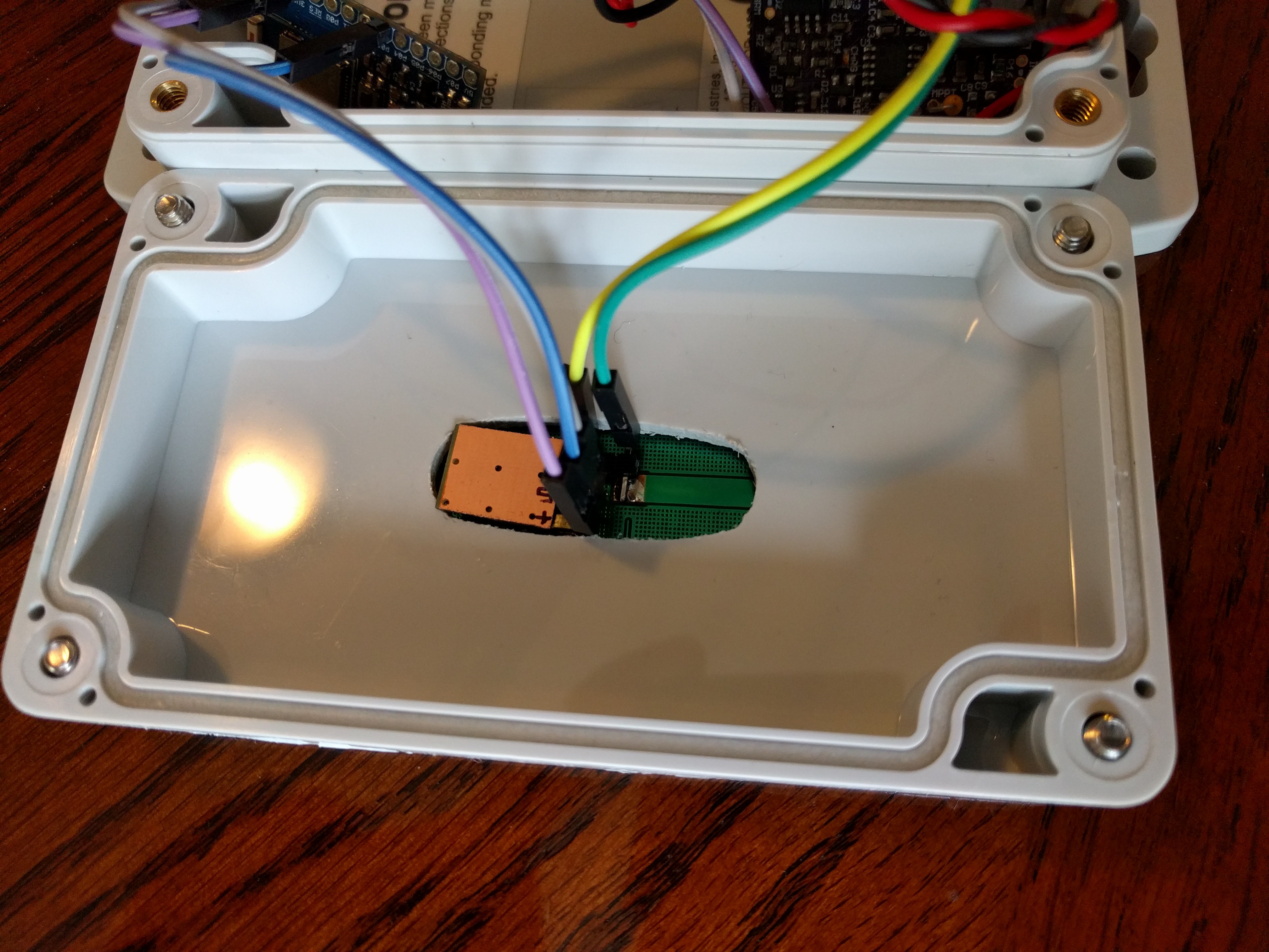
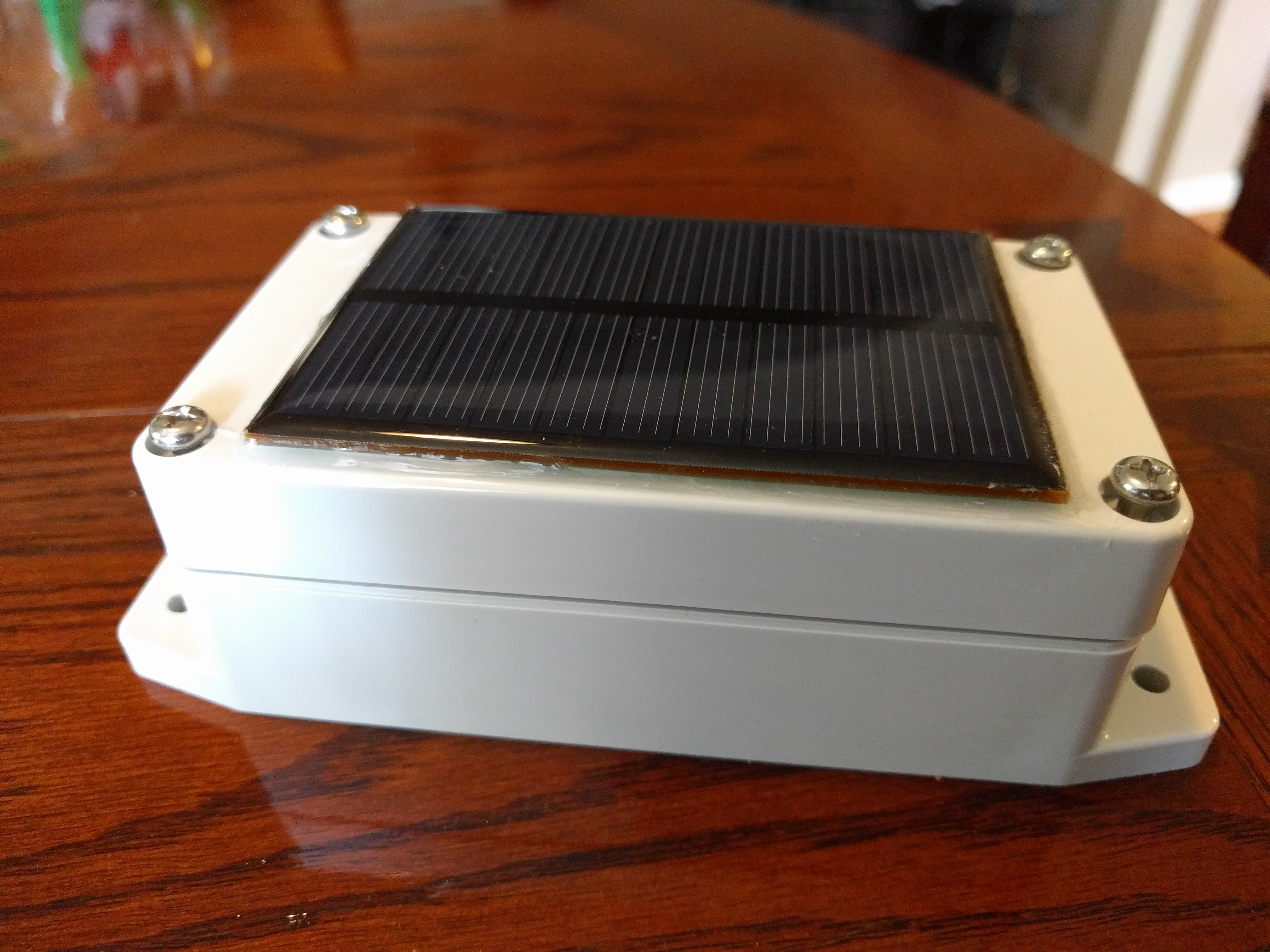
I went with this 4-1/2" x 2-1/2" x 1-5/8" case from McMaster. It's IP65 rated and should be good enough for a prototype. I had to make a hole in the front cover to be able to connect the solar cell:
![]()
In this picture you can also see the little board I used for the buzzer and driver transistor. The idea was that if the buzzer was glued against the solar cell, the sound would be louder than if it was just in the box. Nice theory. :) In practice, it didn't work out that well.
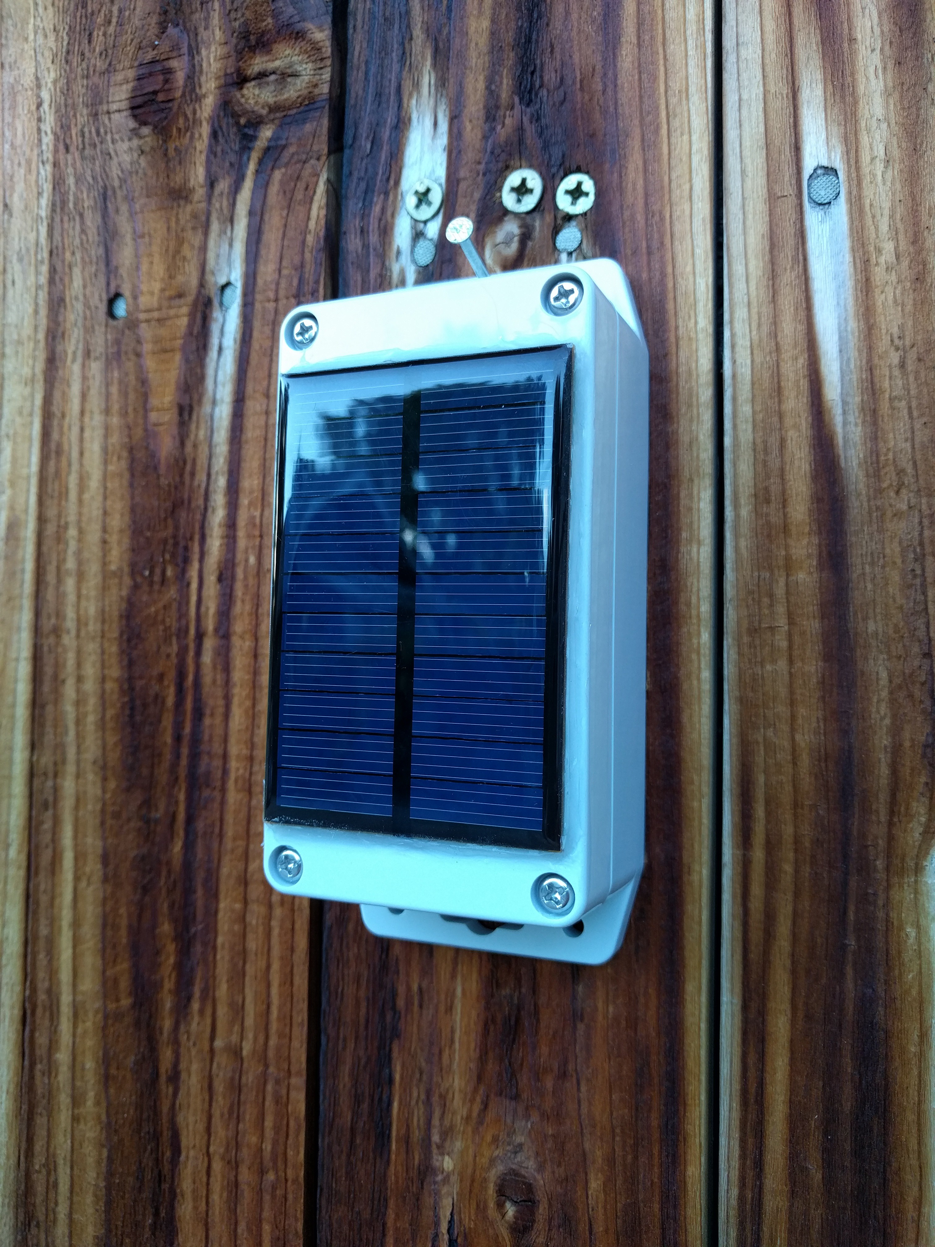
To attach the solar cell to the case, I used some VHB tape and then put silicone around the edge of the solar cell so hopefully no water can get behind it:
![]()
Now this may look pretty good and work decently for a prototype, but I have no illusions about it being the final solution. I have a lot to learn when it comes to the design of rugged systems that need to endure years of exposure to the elements.
For one thing, the idea about the current enclosure is that it's sealed. Of course, making a hole in it and sealing it with silicone probably compromised that.
Also, when this thing sits in the sun, it will get very hot inside and pressure will build up. Some of this pressure will escape and may compromise the silicone. The worst thing about that is that when it cools back down, the pressure inside will drop, pulling air, and possibly moisture, back in to the case.
My #WiFi Logger project is an effort to hopefully learn about these kinds of issues. It will monitor the charging system and also environmental conditions inside the case.
-
BLE module
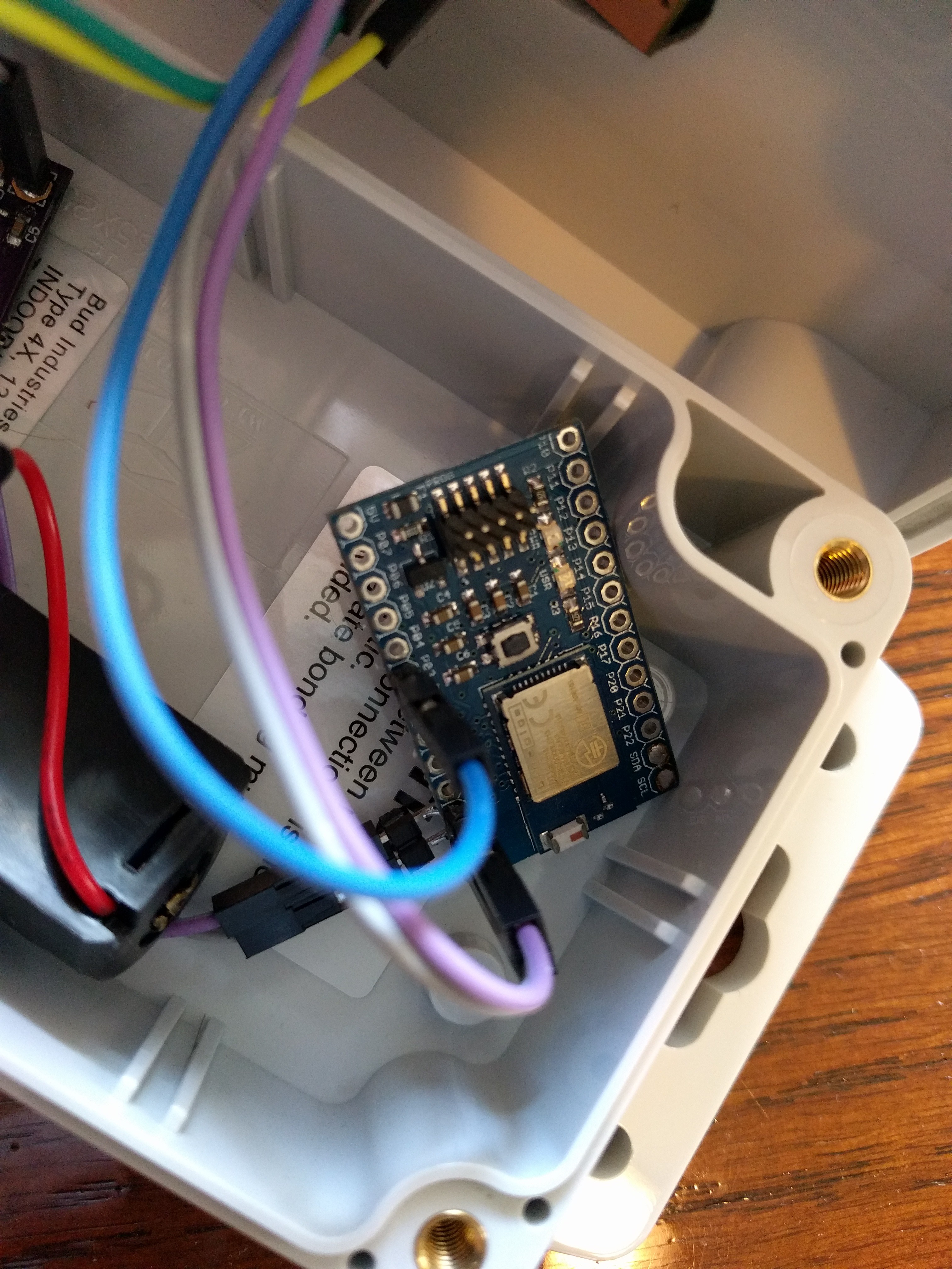
10/02/2016 at 20:56 • 0 commentsAs mentioned before, I wanted to use components I had experience with to speed up the prototyping process. For the BLE module I was first looking at SiLabs' BGM111 module, which was the last one I had used in a consulting project. That implementation had used a separate micro with BGLib/BGAPI. Previously I had also used their BLE112 module with BGScript. Their simple BGScript language seemed to be just the right thing to use for a quick prototype like this.
Then I found out that BGScript doesn't support PWM yet on the BGM111. I had intended to used PWM to easily implement the sound signal generation. So I decided to use the BLE113, which is very similar to the BLE112, instead. I still had a very convenient breakout board by Jeff Rowberg laying around, which was ideal for this.
Here's a picture of the breakout module in the system:
![]()
Once I had determined that PWM indeed works, it was time to look at the enclosure and write some code!
-
Power system
10/02/2016 at 20:35 • 0 commentsOne of the goals of this project was to be able to prototype quickly. So I wanted to mostly use components I already had laying around, was already familiar with or had previously worked with.
Many BLE beacon projects run from a coin cell, but I decided against that. The eventual goal would be to have a product that could be installed by local governments on their street infrastructure, and having to replace batteries just wouldn't do. These things would have to be installed and work reliably for years without issues and with zero maintenance. The current consumption would also be higher than for normal beacons, because of the sound generating system. To keep the system rugged, I would prefer to not open holes in the enclosure to let the sound out, so the sound system will likely take a good amount of power to get through the enclosure.
If a blind person was commuting, the system would likely be activated at least once a day, but of course there could be multiple people and multiple activations per person. For prototyping purposes it would be a good idea to oversize the system and not have any problems.
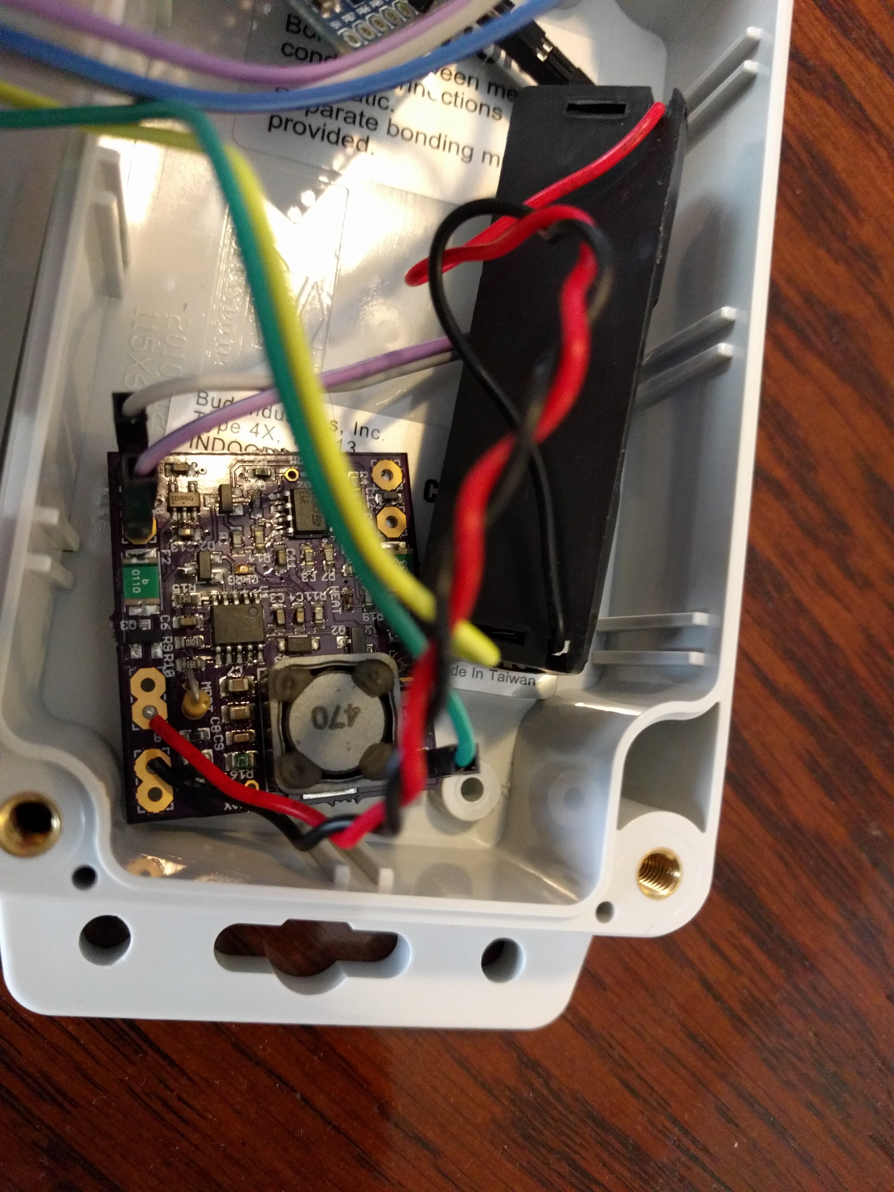
I have a lot of experience with LiFePO4 batteries from other projects such as #LiFePO4wered/USB and #LiFePO4wered/Pi, and my most recent project in that area was #LiFePO4wered/Solar1, so it would make sense to use this project in this one to develop both in tandem. :) Here's a picture of the #LiFePO4wered/Solar1 and LiFePO4 battery used in my prototype:
![]()
I used a small monocrystalline solar cell from AliExpress for this prototype. The cell's advertised peak power is 0.6W (5.5V @ 120 mA). Again, more than needed, but I want this to work even if it's installed on a north-facing wall or in the shade.
The #LiFePO4wered/Solar1 was configured for an MPPT voltage of 5.1 V and maximum charge current of 444 mA. This is way more than the solar cell can provide, but it's the minimum value with the current components used in the #LiFePO4wered/Solar1. Lesson learned: change the components to lower the minimum charge current. Since the system uses MPPT, it's not a huge problem because the charge current will automatically be lowered to a level the solar cell can support. Some quick testing showed the charge current to be more like 25 mA when not in full sun.
This power system should be good enough for a prototype and I'll be able to learn about and optimize the #LiFePO4wered/Solar1 design in the process. :)
SoundBeacon
Audio BLE beacon that can be activated by the blind to find exact locations of doorways, bus stops, crosswalks, etc.
 Patrick Van Oosterwijck