-
Explaining the color scheme
08/22/2018 at 19:15 • 0 commentsOne of the main features of this watch is that is capable of showing the time with 3 leds. For translating a color scheme to a readable hour you have to do some math in to your head.
Each color represents some number (this table could vary):
Number: Color: 0 Black 1 Red 2 Green 3 Blue 4 Yellow 5 Cyan 6 Magenta 7 White Lets have for example Green - White - Black, would be translated to 2 - 7 - 0
270 in octal is 2 * 64 + 7 * 8 + 0 * 1 = 184 in decimal. Now, each unit in 184 represents 5 minutes from 00:00h, a total of 920 minutes have passed. 920/60 = 15h and 20m so the time is 15:20h.
There're some handy hours:
Color Octal Decimal Hour Black Black Black 000 0 00:00h Black Red Yellow 014 12 01:00h Green Green Black 220 144 12:00h Red Red Black 110 72 06:00h Blue Blue Black 330 216 18:00h We can see some patterns, like the 110 - 220 - 330, and probably there are more, so if you found some interesting time saving patterns I'm glad to read it!
-
Testing the TPL5110 accuracy
08/22/2018 at 18:36 • 0 commentsOne thing which would helped me a lot was to read the full datasheet before testing nothing, and I say that for this:
So I got an tpl5110, now is time to test how well it behave keeping track of the time. My setup was similar to the previous one, a clock, in this case the timer ic, an arduino for interface with the pc and a precise internet clock, for compare to experimental results.
![]()
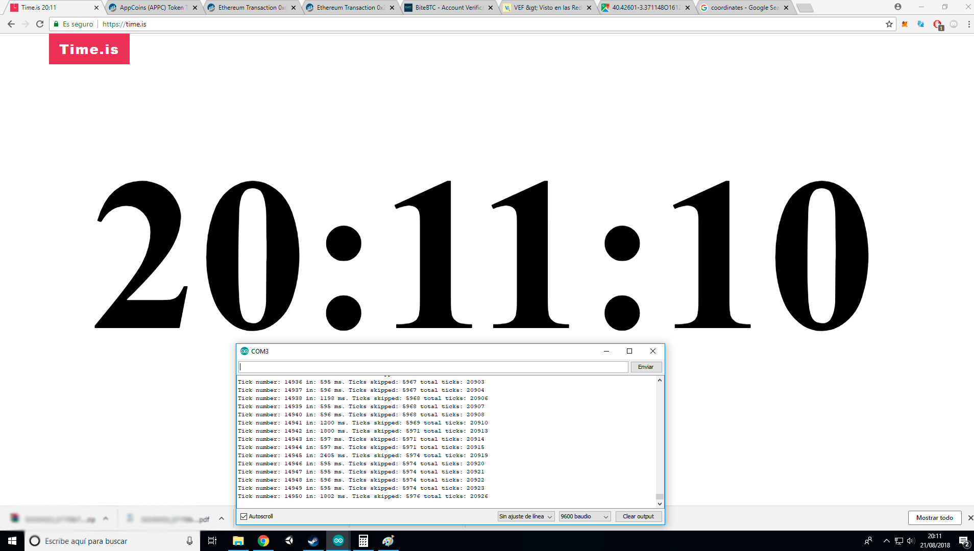
This time I started to count at 16:41:00h, which is a total of 12610 seconds. As you can see this time I added more information, like how many time a tick last (because the TLP5110 requires to select a discrete time duration, I choose 600ms), how many ticks were being skipped (I will explain this in a moment) and the total tick count. I got 20926 ticks, with a duration of 600ms each one is equal to 12556 seconds, so is an error of 54 seconds, the 0.43%, much better than before, but quartz clocks are rated at 10-100ppm, which is 0,01% so I would look for other a ultra low power rtc.
How you can see there are some ticks skipped, so for solving it, the TPL5110 have an input pin which when the uC get the tick right, turn it on for telling the timer that the signal was successfully received. It reduced the skipped ticks to a total of 6, so successful, but I got worse accuracy, a 0.7%
The accuracy was written into the datasheet, I should had read it, so in conclusion, I can handle a 0.43% of error (6 minutes a day) for my initial prototype, but I have to start thinking in to looking for a better timer ic.
-
Testing the accuracy of the attiny45 watchdog timer
08/22/2018 at 18:14 • 0 commentsOne important spec of a watch is the accuracy, a delay of couple of seconds each day is acceptable, but the watchdog timer of most of the microcontrollers is not usually accurate.
For testing it I wrote a small blink code of 500ms with the tinySnore library, a library which allows to sleep the uC with only one line and provides 6.4 micro amps, which is not bad at all.
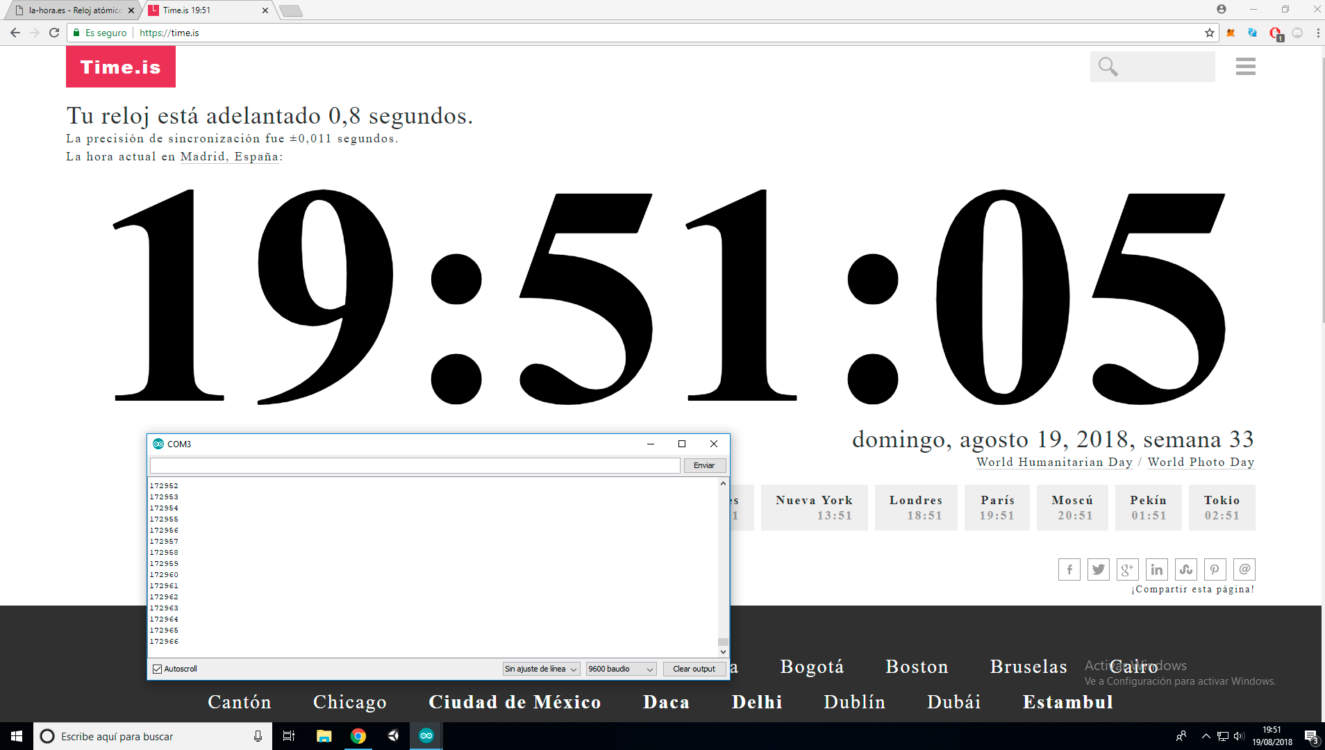
Because I wanted to be precise, and the arduino digitalWrite function add a little delay, I had to directly toggle the PB register. Then I burned into the attiny45 and connected an arduino as a flank detector, connected to the pc through the serial. I counted each tick, which is supposed to last 1 sec, and at the same time I started an online precision timer for two days.
![]()
I started it two days ago at 16:00:59, which is a total of 186606 seconds, and I got as you can see 172966, a 7.31% of error, 105 mins of error each day, an enormous error. I could see how that error in certain way was constant, so could be possible to correct it, but is better to look for an alternative, my first idea was get a TPL5110, a nanopower timer
-
Multiplexing leds and some coding
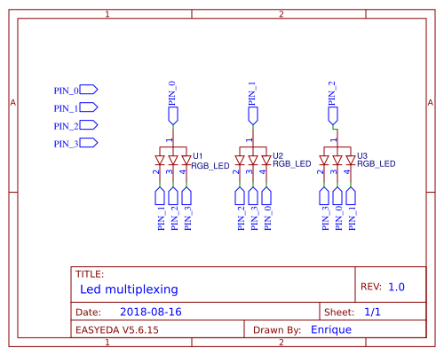
08/16/2018 at 11:42 • 0 commentsOne of the most important things in this project is the display, 3 rgb leds, but 3 rgb leds means 3 * 3 colors = 9 pins. One solution is a charlieplexed arrangement, which allows me to use only 4 pins
![]()
so in theory, playing with different pin digital outputs and inputs is possible to turn an specific color.
So let's code a bit:
first I need a function that turns all off:
// turn all pins off by putting them in a high impedance state
void turnOff(){
  pinMode(PIN0, INPUT);
  pinMode(PIN1, INPUT);
  pinMode(PIN2, INPUT);
  pinMode(PIN3, INPUT);
}
The pinMode function allows to set a pin as a 0/1 (OUTPUT) or as a high impedance state (INPUT). Setting it as an input is like turning that pin off, no digital data coming out that pin.
So now I need a function for control which color of which led turn on, so there is:
// turns on one led one color at time, 3 available leds and 3 available colors (0 = BLACK, 1 = RED, 2 = GREEN, 3 = BLUE)
void turnOn(byte led, byte color){

  //turn all pins off
  turnOff();

  switch(led){
    case 0:
      // set the common cathode on
      pinMode(PIN0, OUTPUT);
      digitalWrite(PIN0, HIGH);

      // set the mapped pin to off
      if(color == 1){
        pinMode(PIN1, OUTPUT);
        digitalWrite(PIN1, LOW);
      }

      if(color == 2){
        pinMode(PIN2, OUTPUT);
        digitalWrite(PIN2, LOW);
      }

      if(color == 3){
        pinMode(PIN3, OUTPUT);
        digitalWrite(PIN3, LOW);
      }
      break;

    case 1:
      // set the common cathode on
      pinMode(PIN1, OUTPUT);
      digitalWrite(PIN1, HIGH);

      // set the mapped pin to off
      if(color == 1){
        pinMode(PIN2, OUTPUT);
        digitalWrite(PIN2, LOW);
      }

      if(color == 2){
        pinMode(PIN3, OUTPUT);
        digitalWrite(PIN3, LOW);
      }

      if(color == 3){
        pinMode(PIN0, OUTPUT);
        digitalWrite(PIN0, LOW);
      }
      break;

    case 2:
      // set the common cathode on
      pinMode(PIN2, OUTPUT);
      digitalWrite(PIN2, HIGH);

      // set the mapped pin to off
      if(color == 1){
        pinMode(PIN3, OUTPUT);
        digitalWrite(PIN3, LOW);
      }

      if(color == 2){
        pinMode(PIN0, OUTPUT);
        digitalWrite(PIN0, LOW);
      }

      if(color == 3){
        pinMode(PIN1, OUTPUT);
        digitalWrite(PIN1, LOW);
      }
      break;
  }
}
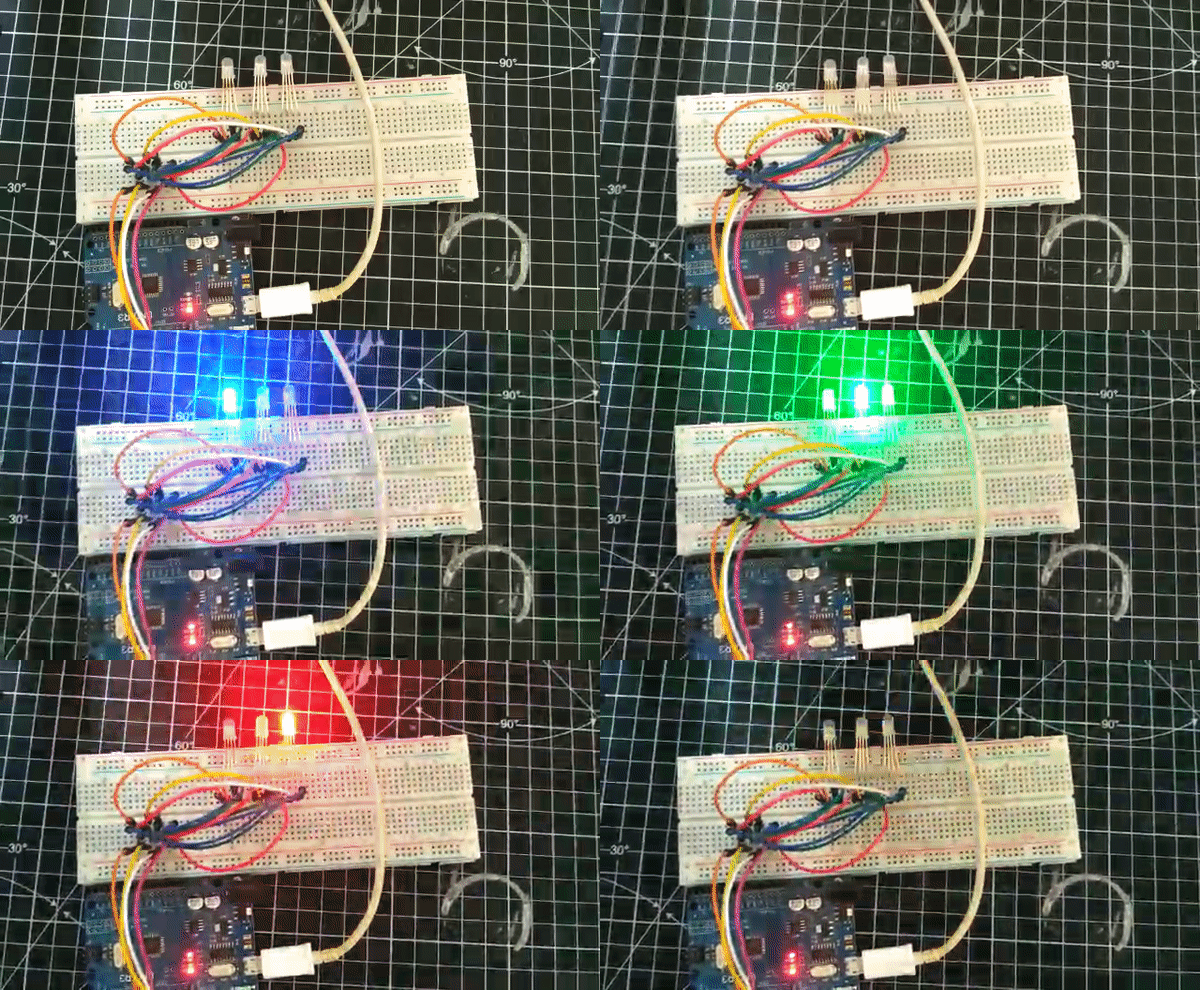
What this function does is to turn on one led one color (R/G/B) at time turning off the rest, so lets test it:
![]()
Now we want to represent decimal numbers as an octal color coded ones:
void drawNumber(int number, int milliseconds){

  float startedMilliseconds = millis();

  // run the while for the time set
  while(startedMilliseconds + milliseconds > millis()){

    // loop for each led
    for(int i = 0; i < 3; i++){

      // n is the octal number corresponding to ith digit, this is the main decimal to octal conversion
      int n = (number/round(pow(8, i)))%8;

      // loop for each binary digit on n
      for(int j = 0; j < 3; j++){
        // we get the jth binary digit and check if is a 0 or a 1, turning on or off the corresponding color, for example 5 = 101 which would turn red and blue = magenta
        if((n/round(pow(2, j)))%2 == 1){
          turnOn(i, j+1);
        }else{
          turnOn(i, 0);
        }

      }
    }
  }
  turnOff();
}
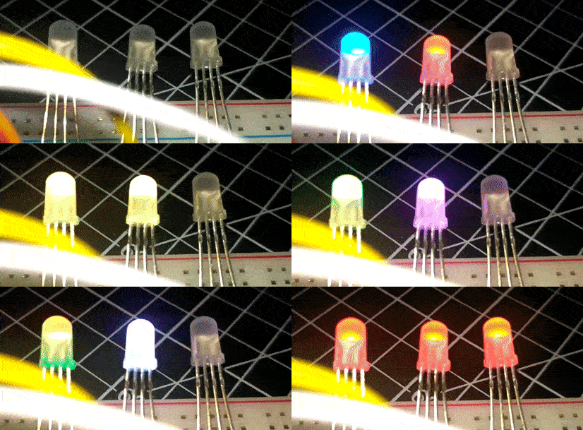
We run the function in a while loop for the time that we want the leds turned on, after that, we convert the digital number ("number" variable) into 3 octal digits, each one corresponding to one led, this digit is called "n". Now we get the n and we decompose it into binary digits in the second loop. How the n is a number between 0-7, we only need 3 binary digits. Each binary digit is represents a RGB color on a led so for example the 5 = 101 would turn on the red led, would turn off the green led and turn on the blue, so we would get magenta. Let's see it in action:
![]()
And that's, sorry for the terrible quality, I had to compress the gif
So now, we can get any number between 0 - 511 and show it with 3 RGB leds and 4 microcontroller pins!
Stay tuned for the next log
-
Crappy super caps
10/05/2016 at 17:28 • 0 commentsFinally, after get my package (my package returned to china for not at home) I tested these caps. The function were avoid the fast discharge of the battery (the batteries used are so small and doesn't allow more than 0.1ma discharges), but after powering one I doesn't got a slow charge, instead that I was measuring the same voltage of the power supply. I left it for a few minutes and then I tried to discharge with a led... But no, I got less than 1 volt... and that doesn't last long... that 1v decreased to 0v in a few seconds without powering anything. I got the same result on a few caps... Isn't good idea buying 0.2$ caps on aliexpress valued at 2$/each on mouser.
The capacitors are: XH414HG IV01E (0.08f, 3.3v and super small)
09/26/2016
-
No more attiny10 :(
10/05/2016 at 17:17 • 0 commentsAfter learning how to program attiny10, optimizing it, sleeping it, making work the sw2812b and so much work I have to say goodbye. When was all in a protoboard with all components working perfectly and all coded I only saw one led powered on... I have realised that 32 bytes of ram isn't enought for manage two leds and one clock. I chose the attiny10 because was the only aviable on a sot-23 package without looking so much the ram details.
I have found a nice sustitute, the attiny45 on a TSSOP, measuring 4.3mm * 2.9mm, not bad ;)
I hope that the package arrives soon
10/01/2016
 Enrique