-
v2 case
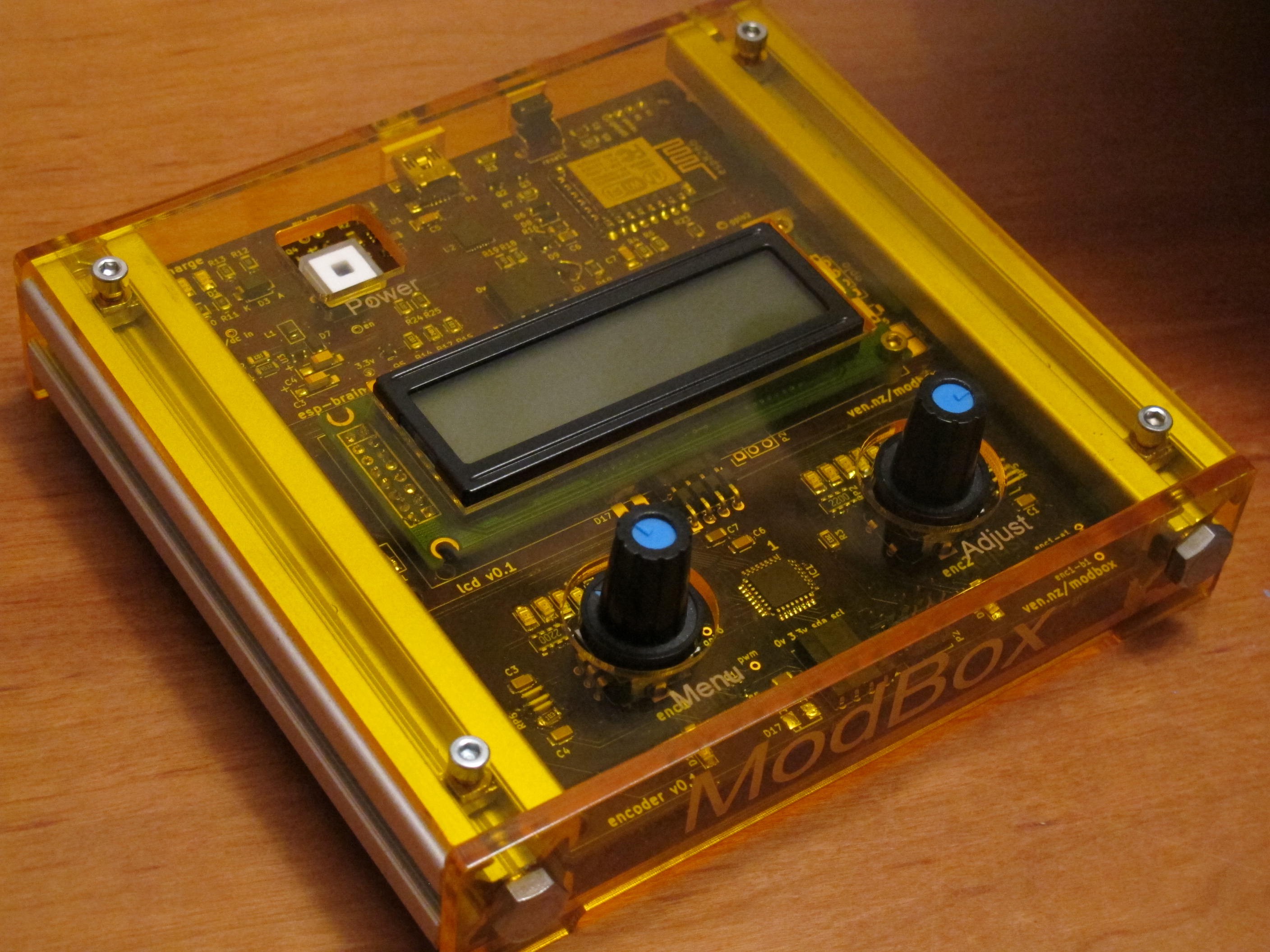
01/12/2017 at 21:53 • 0 commentsafter feeling the wooden box for a few days I noticed a few places where the corners could be rounder, the fit better, ideas for labels etc. These updates were then cut from an orange tint acrylic. I'm pleased with the result!
-
v1 case for mpd controller
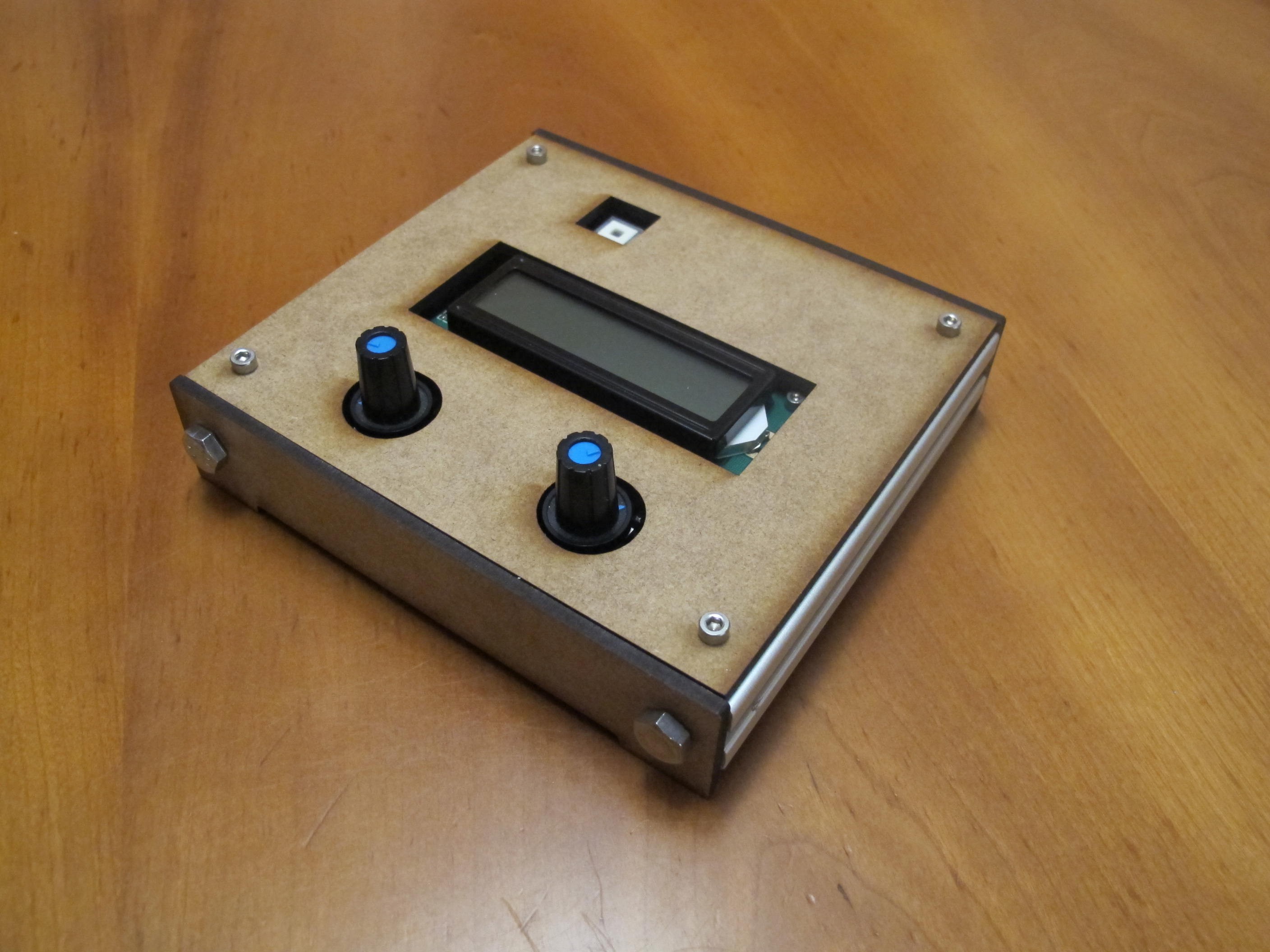
01/08/2017 at 17:31 • 0 commentsThe original application for modbox was an mpd (music player daemon) controller. I made a cad model of the pcbs and box in fusion360, then 3d printed some pcb spacers and laser cut some mdf for the case.
-
build/test/code new pcbs
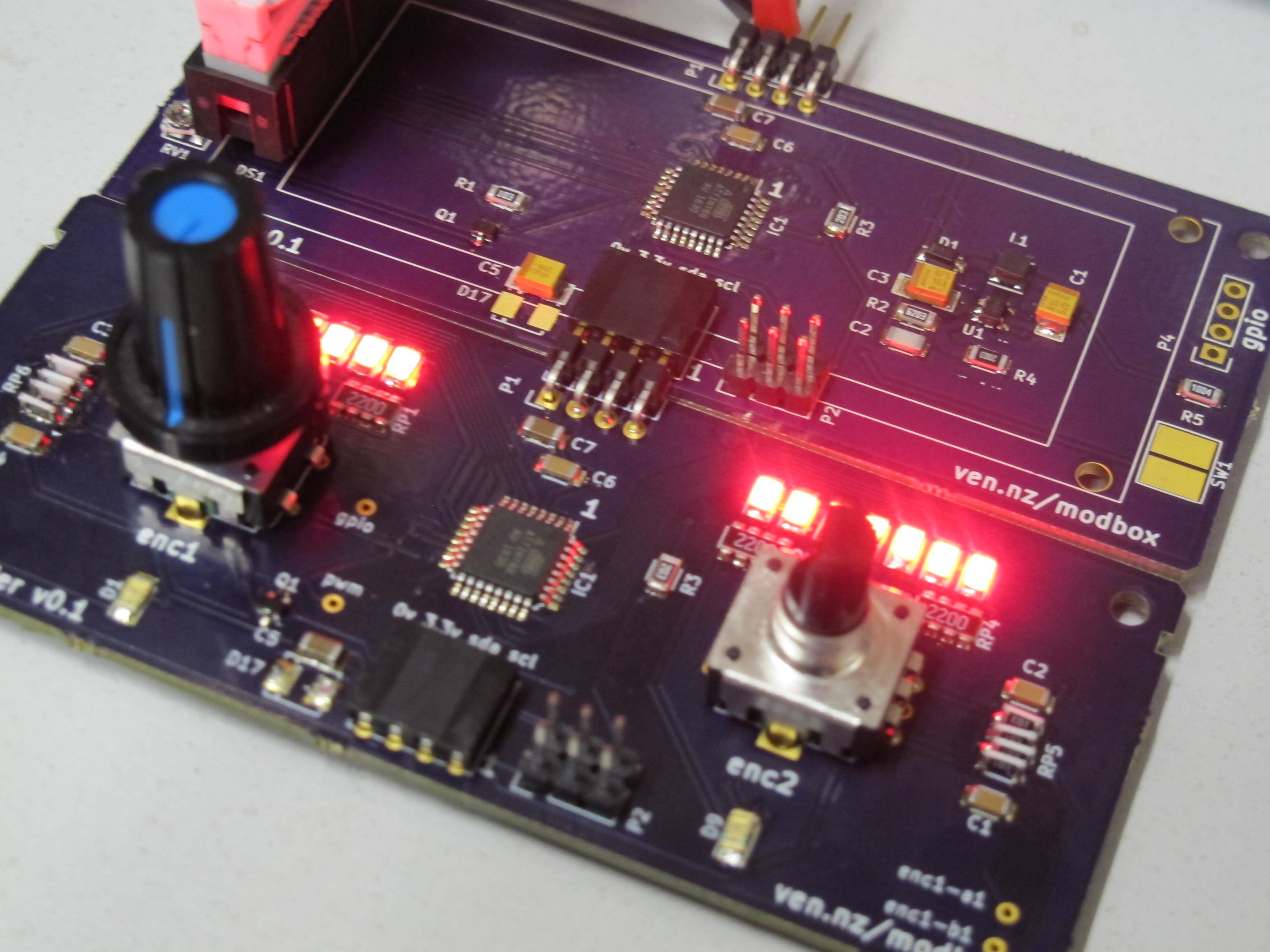
11/24/2016 at 17:08 • 0 commentsknobs & lcd PCBs arrived from OSHPark a few weeks ago - today we got round to building them up and writing some test firmware to flash the lights.
All in all very smooth, both boards I could flash with no problems, though it seems the knobs board with all its leds needs about 3.5v to flash. 3.3v is fine for running though. Both boards together draw about 40ma. There is pwm control on the led backlight and leds so this will vary.
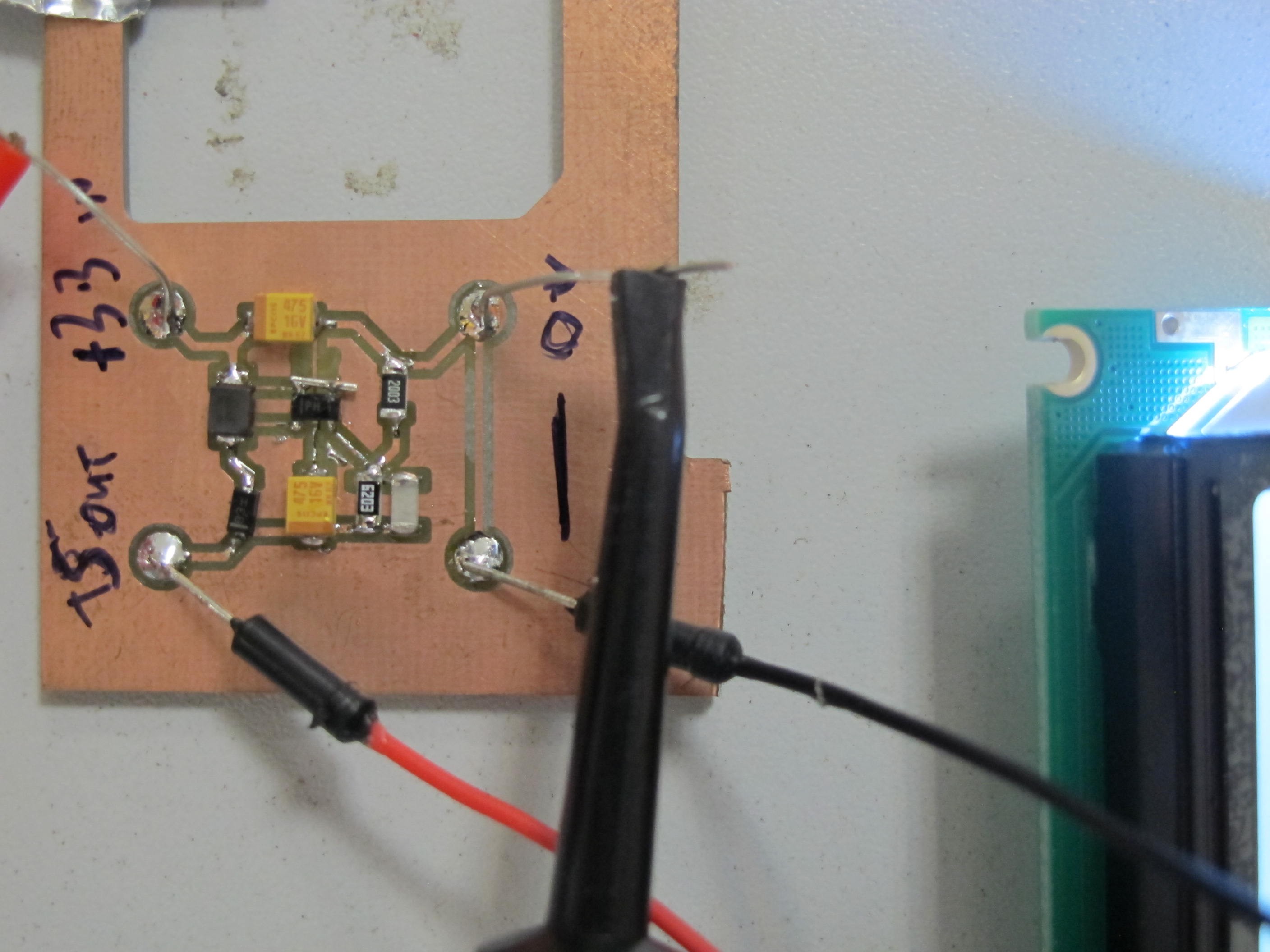
The dc boost for the lcd works as well as the prototype - haven't tested it fully to see if it's any better with proper ground plane.
First time for me filtering encoder knobs, I checked the before/after on the scope and I wasn't surprised that spinning knobs fast without filtering ends up with missed steps.
Mistakes:
resistor packs - the large size I randomly chose were amazingly expensive, about 8 euro for 10 pieces, the 0604 ones were about 1 euro for 10. I used the big packs for the 4 I needed for the leds, but the 2 for filtering the knobs I did by standing 10k 1206 on their sides.
pins were wrong on the potentiometer foot print I made!
through holes for the lcd board were too small for the connecting wires, so we've had to solder the socket on top of the board.
-
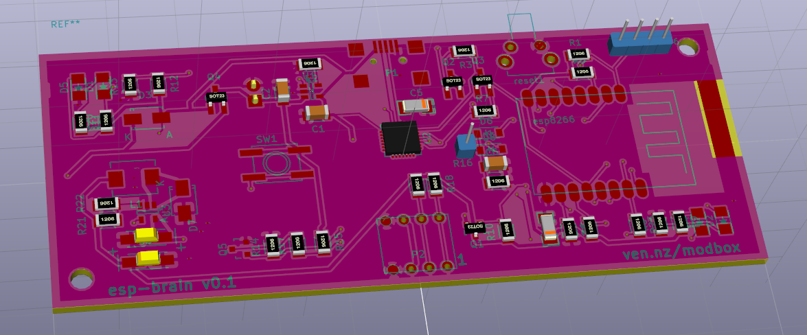
modbox brain pcb
11/03/2016 at 14:51 • 0 commentsJust finished the 1st draft layout for the brain.
Not convinced about the DC buck layout yet, and still need to find the right button.
Schematic is here https://github.com/mattvenn/kicad/tree/master/modbox-brain
![]()
-
firmware, ids, pcbs, lcds
10/21/2016 at 09:16 • 0 commentsI've updated the firmware so it is stateless apart from the ID of each module. when the controller boots up and registers on mqtt, it receives a set of configuration that tells it what the modules need in terms of data and what ID they are.
Following a chat with Mike from Mike's electric stuff, I've decided to set the ids by hand on each module. As each module is both input and output this should be no problem - just press and hold a button at power up to enter id set mode. I added a button the lcd module to make this easy.
The knobs board has been fabbed at OSHpark.com and is on the way.
I've got the LCD board ready to send off, after testing the dc/dc boost for the backlight and logic (5v).
-
tester pcb and software
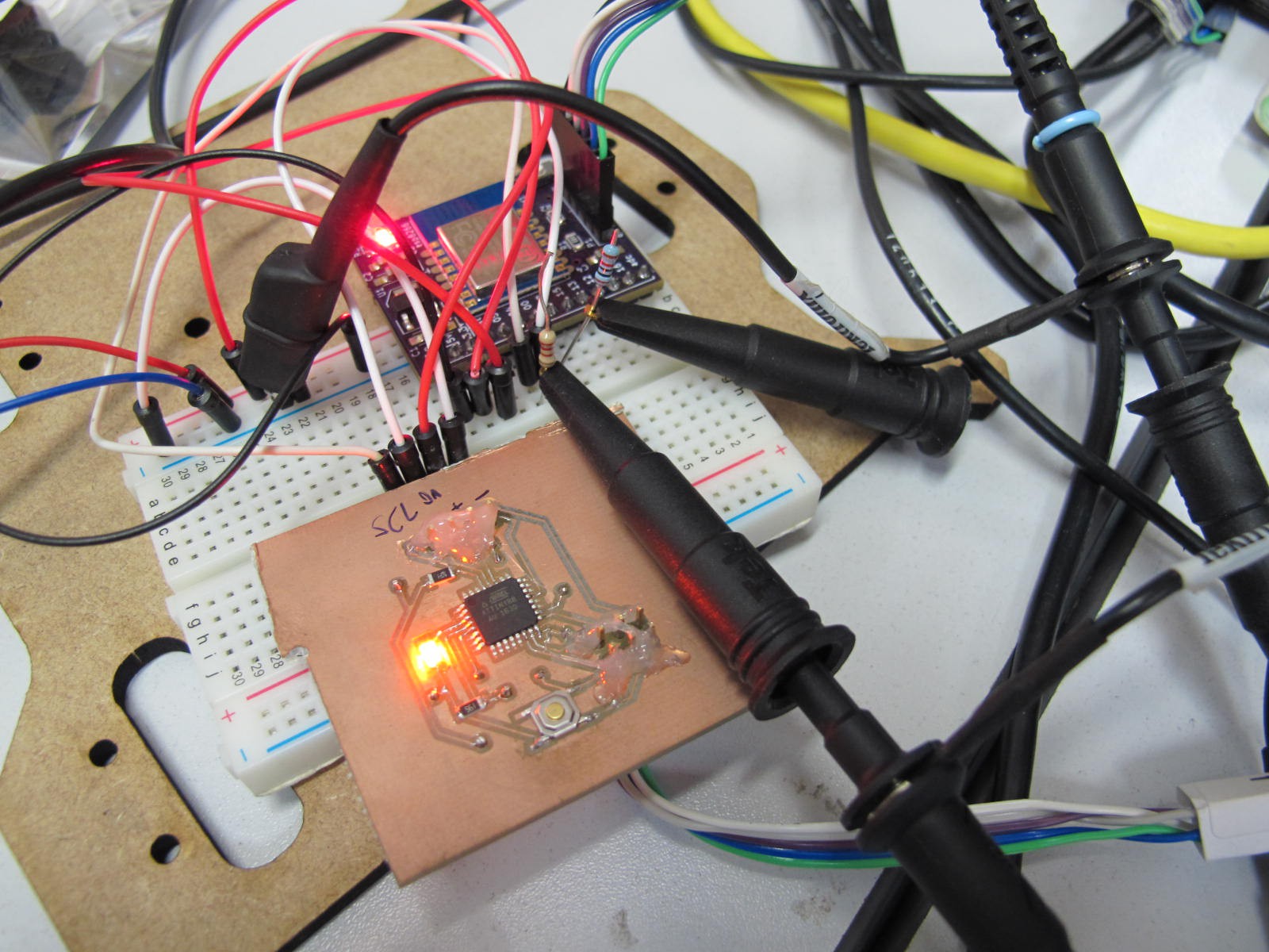
10/10/2016 at 08:31 • 0 commentsProbably should have done this before the knobs pcb - just wanted to check the tiny88 programming and i2c before committing to a proper bit. Anyway, good job I did because I'd mixed MOSI & MISO! I made a cable that swapped the lines and then managed to upload some blinky firmware.
Some very basic proof of concept software is here: https://github.com/mattvenn/modbox
When the button is pressed a message is sent via mqtt to a python server. This sends the message to turn the led off.
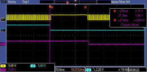
The scope trace shows when a button is pressed (blue line). Yellow is i2c clock, which stops when the esp8266 sends the update. The purple line is the led, after quite a few presses, this was the longest latency, about 30ms. It feels fine, I needed the scope to quantify it.
I'm don't yet understand why the led goes off as soon as the clock starts, I would have thought that between sending the mqtt message and getting a reply there would be time to start polling the i2c bus for updates again.
-
pcb designed
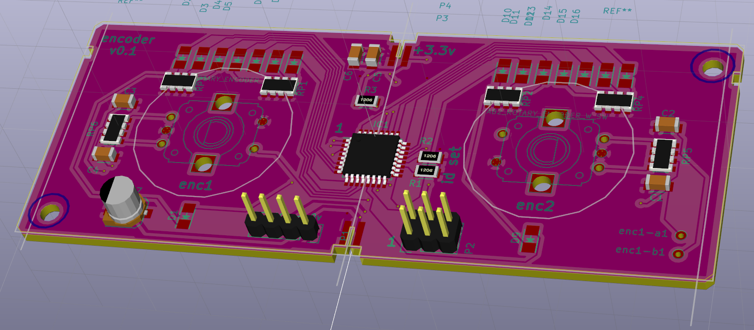
10/05/2016 at 12:03 • 0 commentsI want to test the tiny88 so I needed a breakout board anyway. I decided to try and get close to the right size and added encoders and LEDs as well.
![]()
-
initial design decisions
10/05/2016 at 08:48 • 0 commentsI've made a bunch of preliminary decisions:
- esp8266 + lipo charger + usb/serial converter as the 'brain'
- 4 way bus: i2c, power and ground to connect all modules
- attiny88 for the modules (cheap and supports hardware i2c slave)
- first module will be double push button encoders with led dials
- second module will be an lcd 2x16
- the sides of the box will be 20mm rexroth type aluminium profile, front and back will be laser cut & engraved acrylic, end plates will be wood, delrin, aluminium or acrylic.
- boards will be joined with a connector like this http://es.farnell.com/avx-interconnect/00-9159-004-061-916/card-edge-connector-open-ended/dp/2347864?CMP=i-bf9f-00001000
I want to use an lcd like this http://www.farnell.com/datasheets/2021823.pdf?_ga=1.177301349.1169383904.1463992672
size is 85.0 x 32.6mm
or perhaps an oled.
I'd also like to have a moving coil type dial as a possibility:
http://uk.farnell.com/multicomp/sd506-0-15v/battery-charge-meter-0-15v/dp/4434079
which are 44mm square.
modbox - a modular controller / display
a configurable, modular, remote control and display for hackers
 matt venn
 knobs & lcd PCBs arrived from OSHPark a few weeks ago - today we got round to building them up and writing some test firmware to flash the lights.