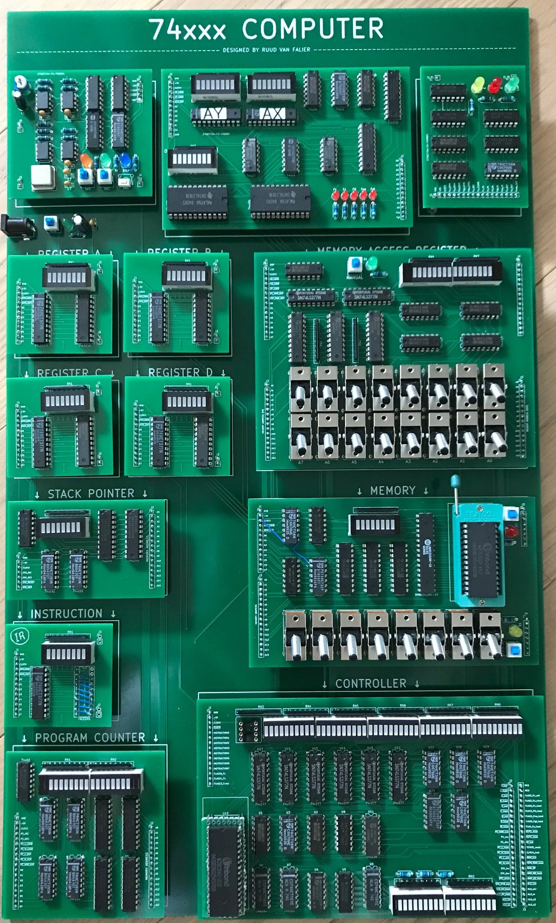
I got pretty far with this project; as far as actually getting everything built on PCB's.
Unfortunately I ran into some issues that prevent the real (non-simulated) computer from properly working:
- I never considered reset circuitry:
- The 74x377 registers don't have a reset line, so the only way of resetting them is to load empty data.
- None of the modules have a reset line exposed
- I tried to "quick fix" this with a 2nd revision of the controller, but it failed
- The controller is way to complicated, which is a result of the way microcode is stored:
- Each instruction takes 6 bytes to store control lines state
- The controller has its own internal clock that runs independent from the rest
- In Logisim this results in a very slow simulation because every microtick (t-state) takes 6 clock cycles to retrieve control lines from the microcode ROM.
These issues don't necessarily mean I have to abandon the project - I could try to fix just those things and move on, but this project was done over the course of 1,5 years and I have learned a lot in that time!
I would prefer to apply all lessons learned to a completely new design.
Even though the final product is not fully functional, I still consider this project to be a success. I've learned so much about (homebrew) CPU architecture, simulating designs in Logisim, assembly languages, digital electronics and much more.
And I'll take all that knowledge with me to the next project!
The 74xx Computer Mk. II project will soon be shared here.
 Ruud van Falier
Discussions
Become a Hackaday.io Member
Create an account to leave a comment. Already have an account? Log In.
sorry to see the project conclude, but once you reach a certain point it is often best to consider it a success and move on! look forward to seeing the next project rolling in what you have learned here! here is a good read about deciding when to move on from a project! https://hackaday.com/2018/09/25/productivity-unfinished-projects-and-letting-go/
Are you sure? yes | no
Liked the article. I think the author moved on to a new and improved version! https://hackaday.io/project/171327-dm-02-8-bit-computer
Are you sure? yes | no
Clever solution for the modules. The best I've seen so far.
Are you sure? yes | no
i love the modularity of the design! i look forward to seeing the next version! sometimes abandoning a project is a good thing! https://hackaday.com/2018/09/25/productivity-unfinished-projects-and-letting-go/
Are you sure? yes | no
Thanks Dave!
I wanted to build something that people who are just getting into CPU architecture could understand.
As mentioned in my reply to Roel, the new design will probably be quite different and not have this same approach in which all the modules are visible.
It has the huge downside of being very expensive to produce.
If I ever apply this design again, I will first build it in a more efficient manner (cheaper to produce and thus cheaper to make mistakes) and only when I'm sure everything is working 100% then I would modularize it.
Are you sure? yes | no
@Ruud van Falier - i hear you about the costs versus modular.... this i my own cpu experiment - https://hackaday.io/project/158510-ddl4-cpu
Are you sure? yes | no
Hi Ruud, too bad that you want to abandon your project, especially now you seem to be almost finished. As for the reset, I think it should be possible to solve it, for instance in one of the following ways (assuming that your program starts at address zero):
- Reset the PC to zero during reset. Might be difficult if the PC is contained in non-resettable counters.
- Force the instruction register to contain an instruction that loads the PC with zero
- Force the Memory module to output a "CLR PC" instruction during reset.
But your controller is indeed very complex. The six-stage loading of the microcode will slow down your cpu very much. When aiming for a new version, you could of course re-use most of your existing modules. The trick would be, that you bring the number of control lines down to a small number, lets say 16, so two parallel EPROMS can provide the microcode. If you want I can help you with that.
I could not find the pdf-schematics of your modules and main board, are they online ?
Are you sure? yes | no
Hi Roel,
Thanks for your encouragement. I have added the PDF version of all schematics to the Git repository: https://github.com/DutchMaker/TTL-computer
Even though this project will be abandoned, it doesn't mean that all is going to waste. I will re-use many of the ideas and components used in this design. There are just too many things wrong with the current design to stay positively involved in trying to fix everything.
Aside from the things mentioned in my post, the modular approach that I used is also a thing: it looks awesome and, when functional, can be a great learning tool - but the main board is a huge PCB and it's quite expensive to produce. Now that I need some adjustments to control lines, it means getting a new main board so it drives up the cost.
My new approach will still be modular, but in a more efficient manner (stackable boards) and with a shield for the Arduino Mega which allows for testing and debugging of all the modules and the entire computer.
About the microcode: I think I've figured out how to bring it all back to 16 bits of data coming out of the microcode ROM, which I can then decode further. That is, together with a few other design changes. There are some notes on this in the Git repo: Documentation/VNext-Ideas.md
I'm still working out some of the details but will share it soon!
Are you sure? yes | no