Close
0%
0%

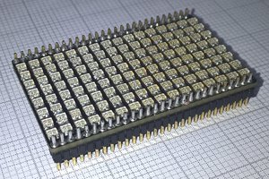
Tileable 8x8 LED matrix

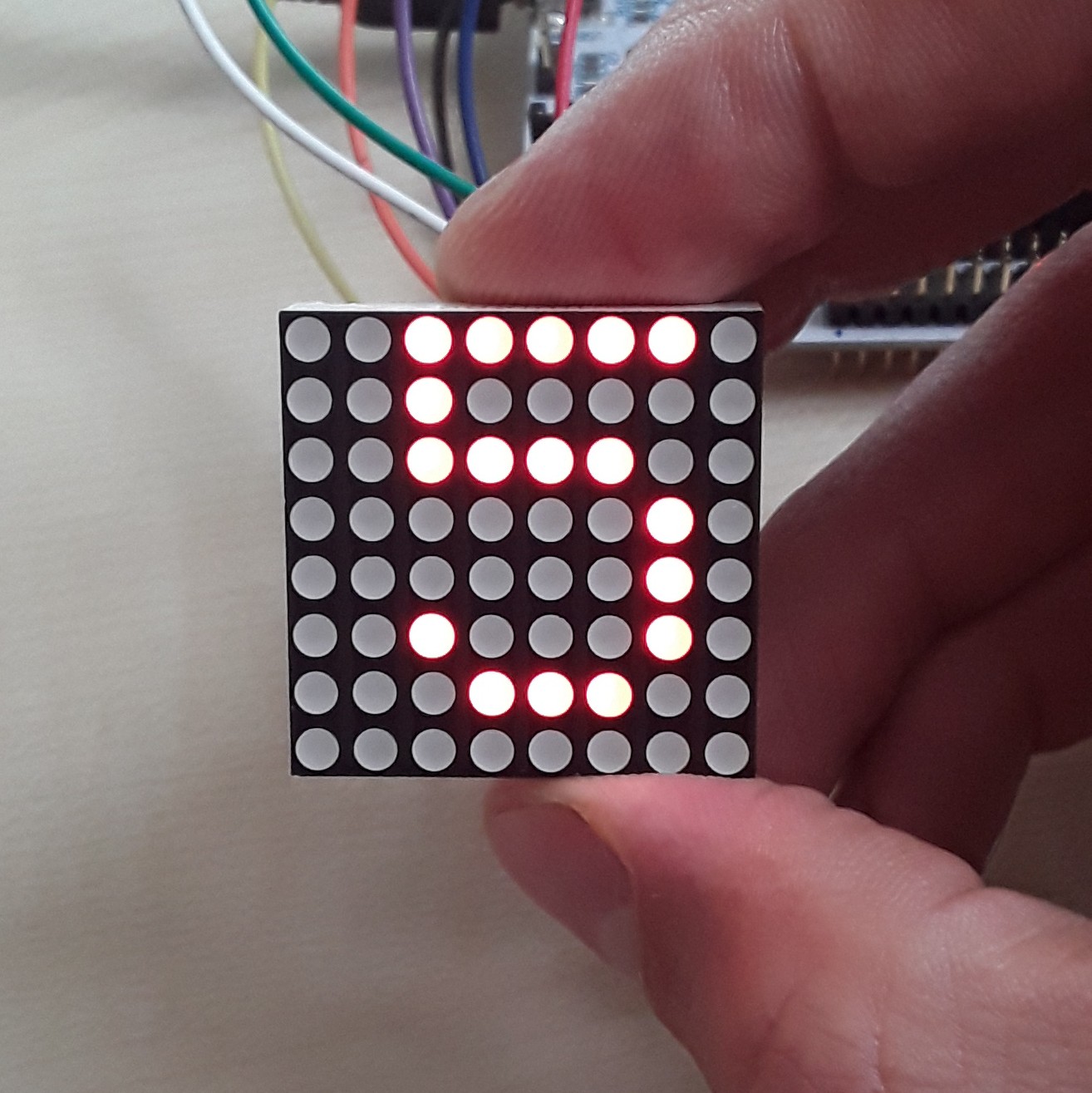
1.0" LED Dot Matrix 8X8 Cascadable Module with SPI interface

Public Chat
Similar projects worth following
This project is an improvement of the DealExtreme 1.8" Red LED matrix Display module (SKU: 408734):
* Correct description of product dimensions : WxH = 32x32mm
* Accessible mounting holes
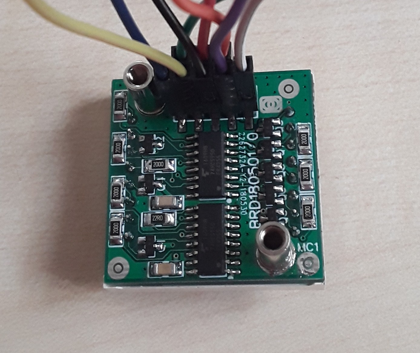
* Using standard 74-logic and discrete components instead of "single purpose" components
* Using straight headers, no wires needed to make connections on the sides.
* Providing 0-100% dimming using PWM. The PWM resolution depends on your platform. e.g. The STM32Nucleo allows for 16bit dimming. Arduino Uno is 8bit dimming. The MAX7219 on the DealExtreme only allows for 4bit dimming.

July 15 2018 : Current status : example code that shows bitmap/glyph morphing on a 2x2 led module matrix

Next steps : Soldering some more boards.

Application ideas:
* ESP8266 NTP-clock

Over the course of the project, development in China hasn't stopped.  It's currently possible to order 4-in-1 modules with the MAX7219 on AliExpress for only €3.78.

If you only want a single piece, you could saw the module to pieces, or buy a single module for €1.09 from AliExpress.

If these modules had been available when I needed them, I probably wouldn't have taken the effort to design my own modules.

  • Dimming the array

    Christoph Tack06/23/2018 at 19:17 0 comments

    The advantage of using the 74HC595 over the MAX7219 and the HT16K33 is that it has an /OE (output enable) pin.  It can easily be used to dim the LEDs from 0 to 100% in as much steps as you like.  Unlike the MAX7219 which is frequently used on LED array modules.  That IC only allows for 4bit dimming control.

    In the video /OE is connected to a 16bit PWM port of the STM32 Nucleo (i.e. pin 6).

  • First test

    Christoph Tack06/23/2018 at 14:11 0 comments

    PCB Assembly

    There's not much to report here.  All parts fit correctly.  I suspect ALLPCB from drilling the holes for the PCB studs a bit too large.

    Pin 1 of the pin headers was not marked in the silkscreen of the PCB.  This will be fixed in the next revision.

    Electronics

    Before connecting power, all connections should be checked.  I felt confident enough to skip this step.  The schematics don't contain any new circuitry to me.

    Unicorn! Revision 0 is fully functional.

    Firmware

    The Adafruit GFX is quite nice.  This will be used to provide high level functionality for drawing lines, character sets etc...  I only need to write a low level driver that can color a pixel at the desired coordinate. 

    It didn't take too long to get this working.

    Next thing is adding dimming functionality.

  • Interconnection

    Christoph Tack05/10/2018 at 20:02 0 comments

    Browsing on LCSC learned me that the cheapest board to board connection is a through hole header/socket connection.

    Pitch

    2.54mm is the most widely used and easy to solder

    Number of contacts

    2x5 & 2&6 pin configuration get you the most bang for the buck when taking into account the cost of the mated connection, i.e. male+female part.  They only cost $0.01 more than the 1x5 or 1x6 configurations.  The benefit of having extra pins is also having extra ground return paths.  This reduces the HF-current loops of the SPI communication.

    PCB Mounting

    Through hole components are cheaper, but require an extra PCB process: wave soldering.

    SMT components are more expensive, but can be reflow soldered with the other SMT parts.  The PCB supports both connector types.

    Mating height

    This might be a bit of a bummer if you really want low profile.  The male header requires 2.5mm height, while the female socket puts 8.5mm on top of that.  This amounts to a 11mm inter-PCB distance.

    Mechanical fixation

    The LED PCB must be supported on both sides to keep it stable.  Adding a few additional header/socket connectors on the corners might do the trick.

    Another option was to use plastic self retaining spacers. Wuerth has these in their product line.  These require a free height of 1.9mm under the LED matrix.

    Instead I opted for SMT studs.  They can be reflow soldered with the rest of the SMT components.  These studs have an internal M3-thread, so they provide for an firm screw connection to the base board.  They're electrically conductive, so can be used to return ground current, a benefit to keep EMI under control.

  • Display Driver

    Christoph Tack05/10/2018 at 19:34 0 comments

    The driver should have SPI or I²C interface and allow dimming.

    SPI

    • MAX7219 : LCSC.com : €2.07 (Digikey >€7)
      • has an internal 8x8bit RAM buffer
    • 74HC595 + 74HC138: 8 outputs, cheap, standard part, PWM-dimming using /OE-pin, Digikey €0.33/pce.  This has the disadvantage that next to SPI, extra control lines for the 74HC138 are required.
    • 2x 74HC595 : One 74HC595 as row controller (only one row should be on at a time).  The other 74HC595 is used as column controller.  Using the same device twice reduces BoM length.
      • no RAM buffer, so each row must be written at least 25 times per second to keep persistence of vision.
    • TLC5925 | STP16CPC26 | CAT4016 | MAX6969: 16 outputs, integrated current source, Digikey €1/pce.  This might be useful for dual color LED matrices.  Here only 8 outputs are needed.

    I²C

    • PCA9685 : LED driver, Digikey €1.80/pce, hard to solder by hand : TSSOP
    • HT16K33 : popular on led matrices, LCSC.com : €0.33, not available on Digikey.

    To avoid that the 74HC595 has to source the current for the LED array, transistors will be used, as switches.  Three transistor types could be used : PNP, NPN and PMOS:

    • PNP would require base transistors.  There's little room for those.
    • PMOS is more expensive than NPN.
    • NPN is used here as a switchable diode.  There's at least 0.7V over the NPN.  In this application it doesn't matter.  It helps for spreading heat over more components, avoiding hotspots.

View all 4 project logs

Enjoy this project?

Share

Discussions

Similar Projects

Does this project spark your interest?

Become a member to follow this project and never miss any updates