-
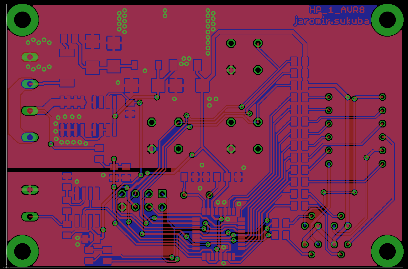
New PCB for plate
07/03/2014 at 07:37 • 0 commentsYesterday I sent nice multipanel to my local PCB manufacturer with a few of my projects and PCBs for new heat plate were included.
![]() Three PCBs were designed and sent for manufacturing, however only one is actually needed for the controller. What is purpose of remaining two boards?
Three PCBs were designed and sent for manufacturing, however only one is actually needed for the controller. What is purpose of remaining two boards?Stay tuned for answer and more details.
-
Old design
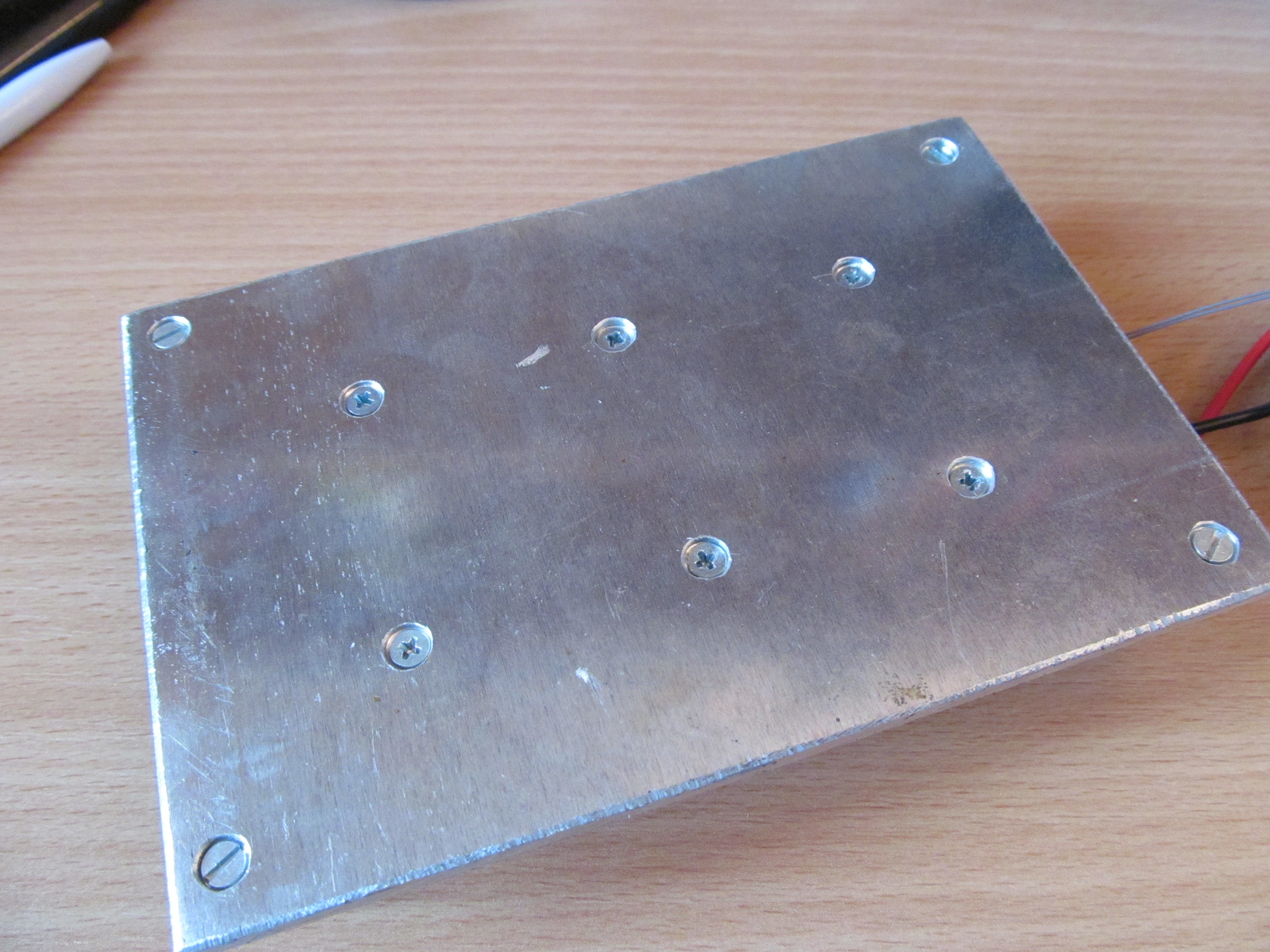
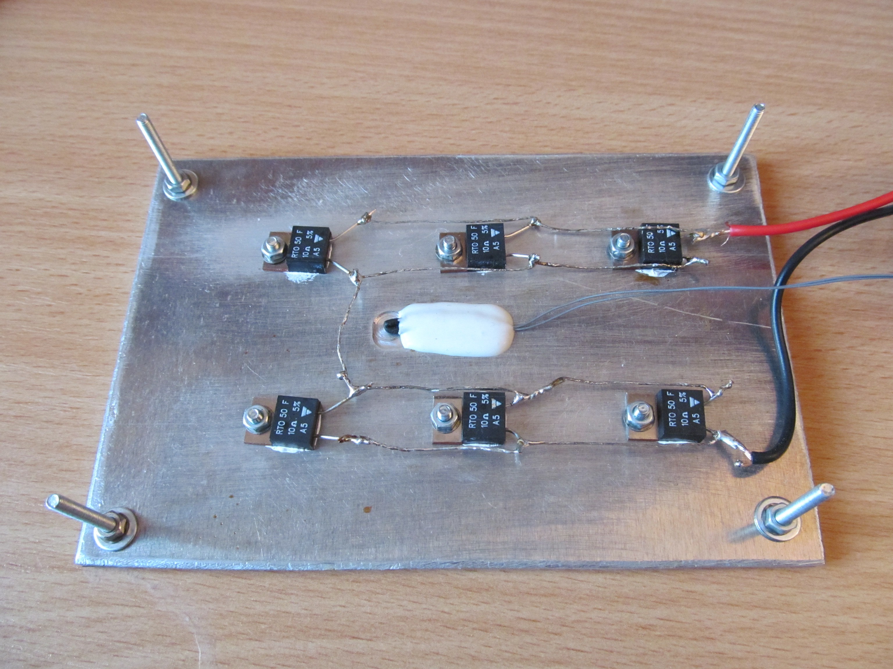
06/23/2014 at 14:22 • 0 commentsNo rocket science involved here - I took 3mm thick piece of aluminium, sized 10x15cm and drilled holes for resistors.
I mounted the resistors with fair amount of thermal conductive compound and connected to two groups of three parallell resistors, forming 6,6Ohm resistor.
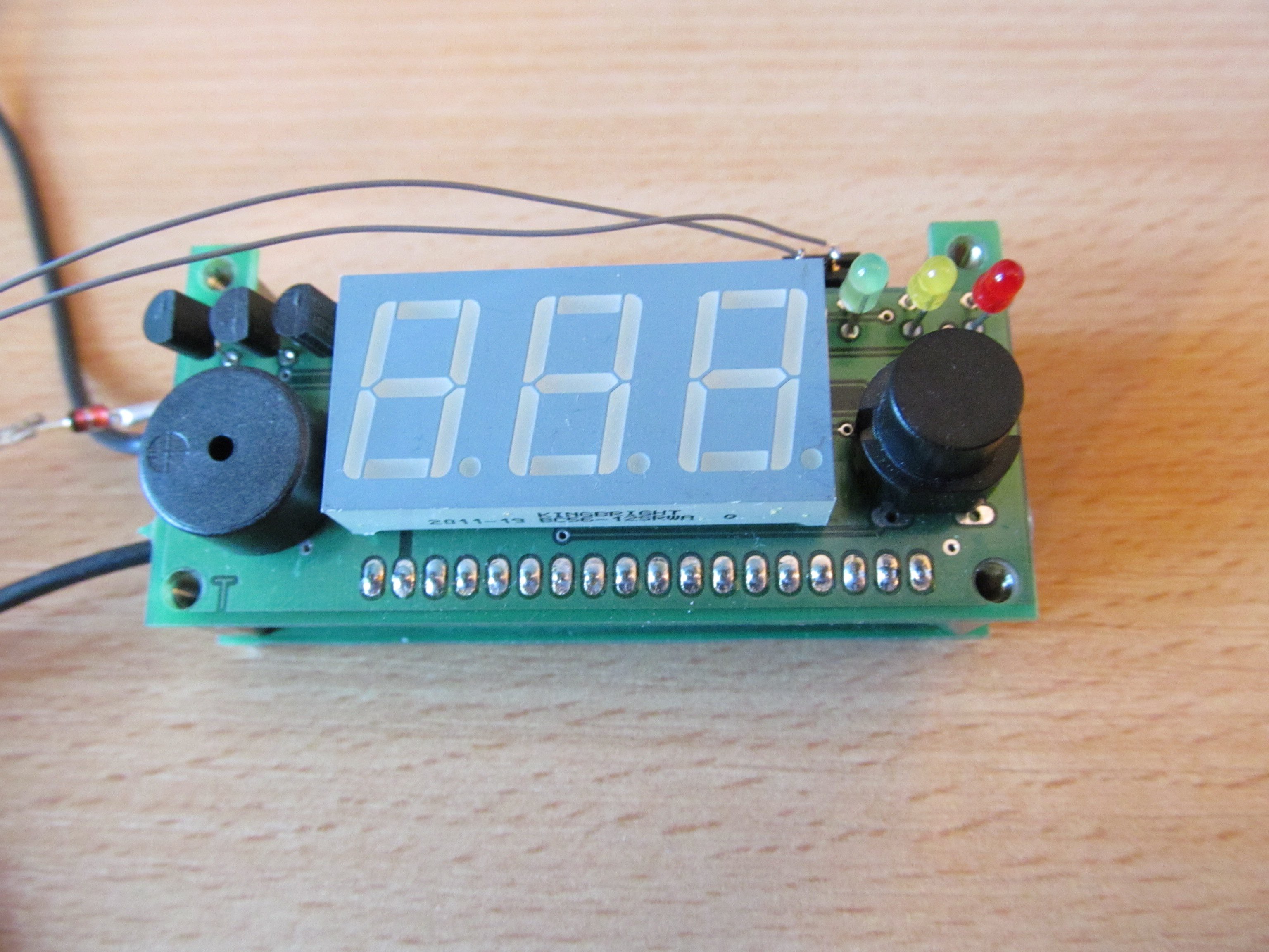
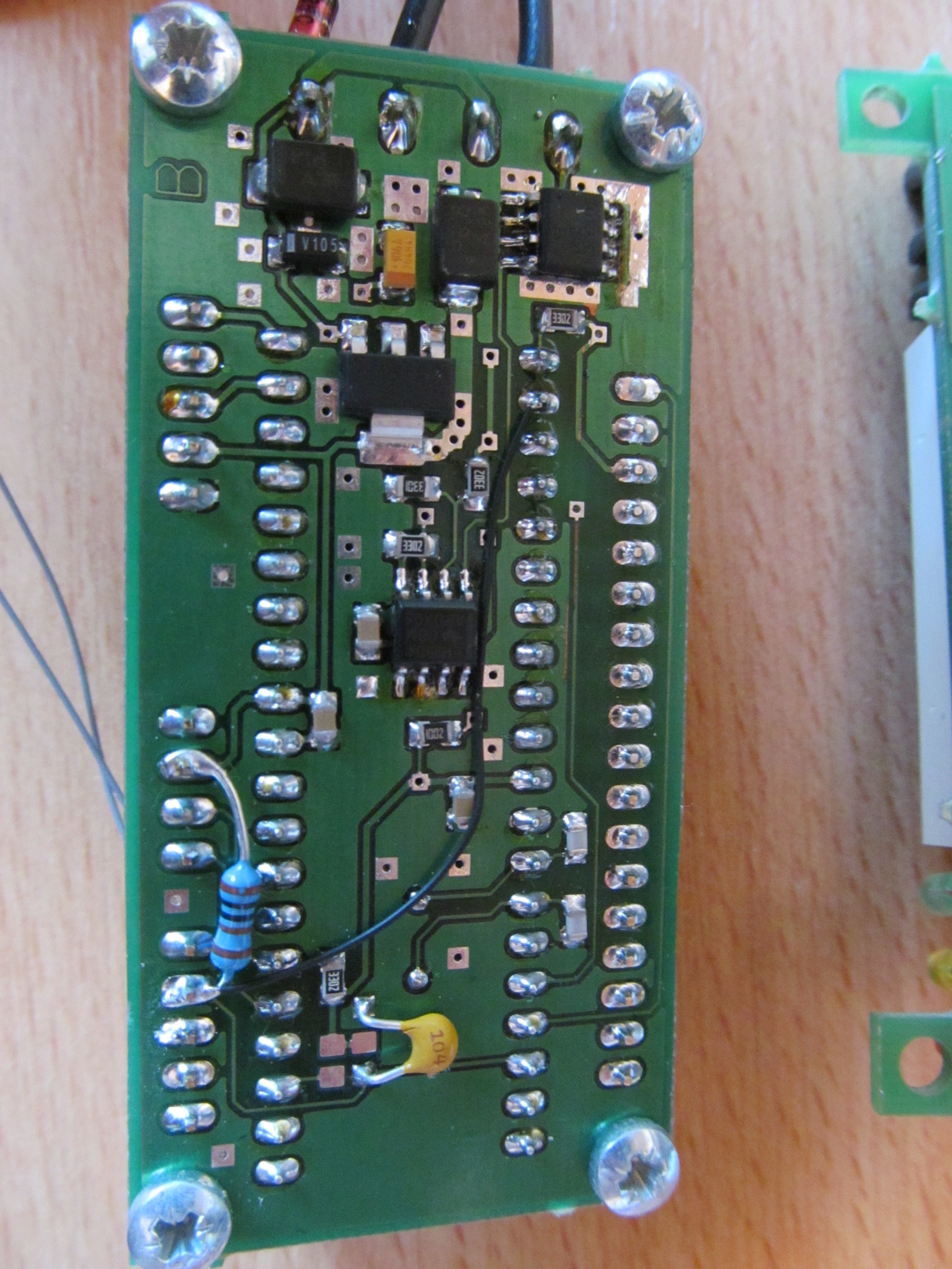
As a controller, I took one of my older projects (thermal controller for I2C temperature sensor) and brought analog input of PIC device to header, with 1,5k pull-up resistor, creating voltage divider with KTY84-130 temperature sensor under that white blob of high temperature epoxy.
The bodge wire is modification for analog resistive KTY84 sensor.
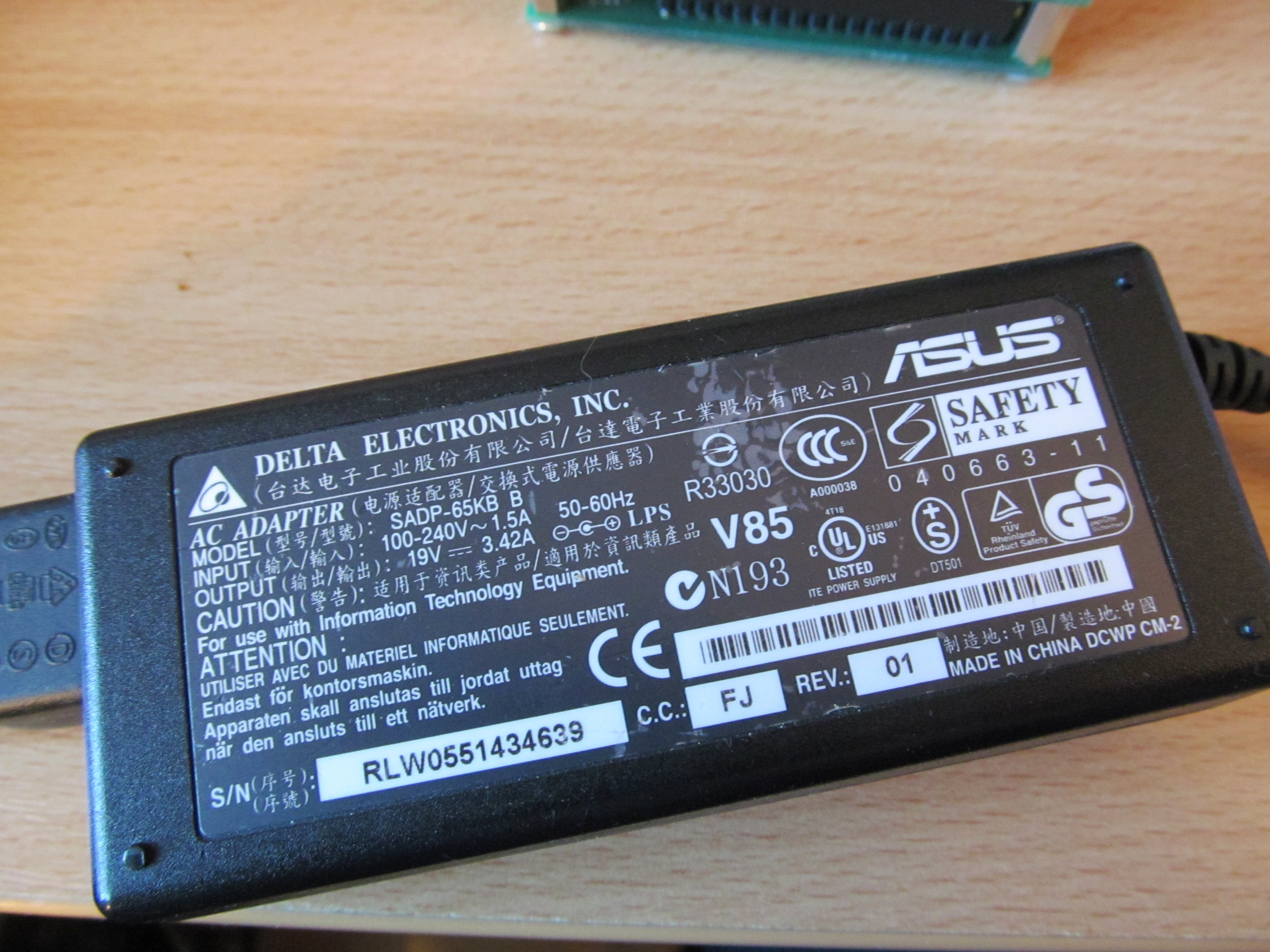
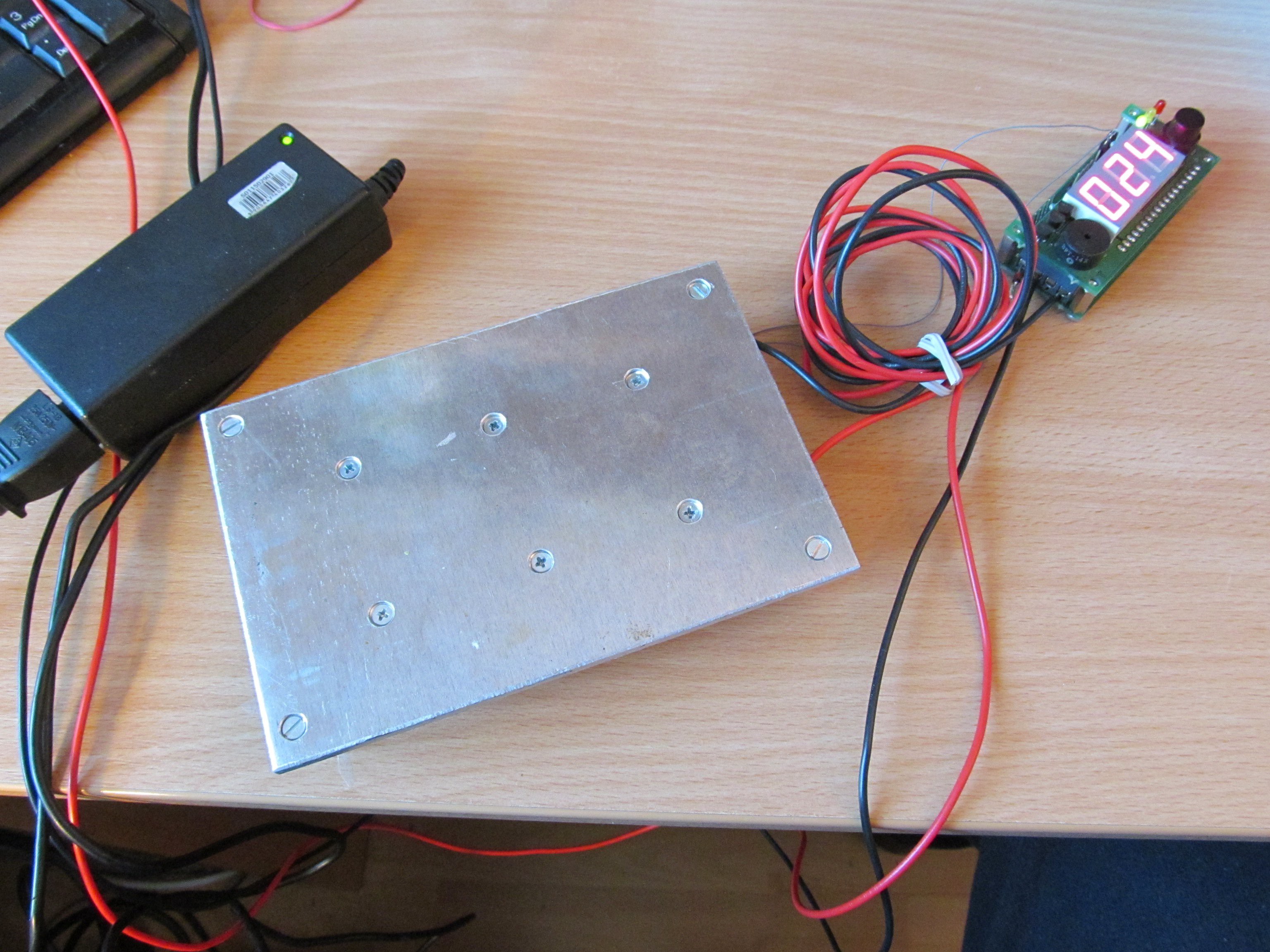
Everything is powered by 19V adaptor from old laptop computer, Those power supplies are quite powerful and you can get them very easily.
And it works, as expected. Notice the long cables. I was lazy to cut them short.
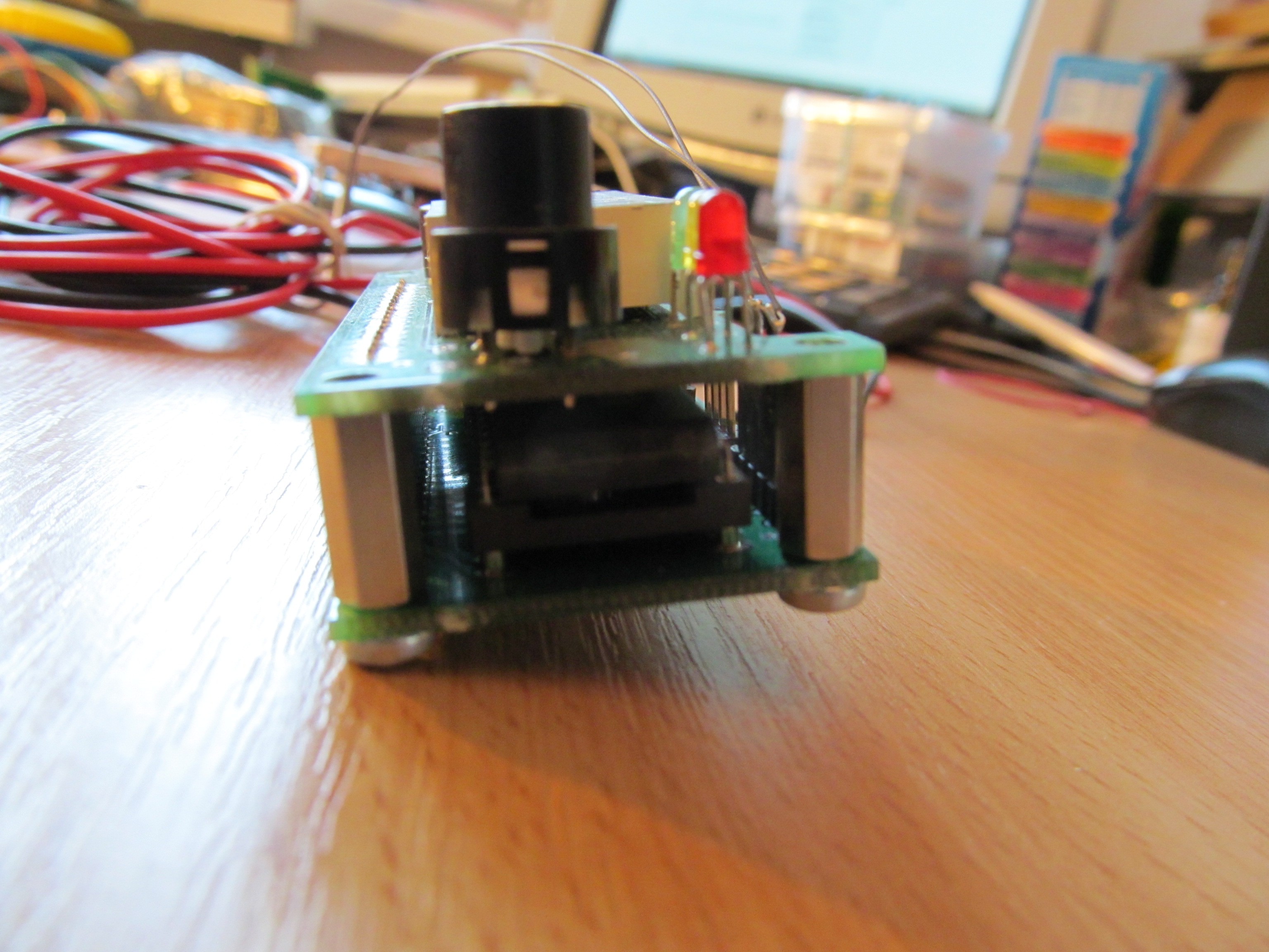
There is only single button to change temperature - there are presets for 0,80,90,100,110,120,130,140,150 degrees of celsius. You can cycle through those temperatures with the button, after pressing it the new temperature is on display for a second (yellow LED is on), then it changes to actual temperature (and green LED is on), so you can watch how it approaches the setpoint. Red LED indicates when heatplate is powered.
There is not much details in this log, as I don't expect anybody to build this thing, however, I uploaded design files on github, so anyone can get inspiration.
What's next?
I'm going to rebuild this, so it will not look as piece of junk.
Soldering preheat plate
Small, simple and inexpensive preheat plate for hot-air soldering
 jaromir.sukuba
 Three PCBs were designed and sent for manufacturing, however only one is actually needed for the controller. What is purpose of remaining two boards?
 I mounted the resistors with fair amount of thermal conductive compound and connected to two groups of three parallell resistors, forming 6,6Ohm resistor.
 As a controller, I took one of my older projects (thermal controller for I2C temperature sensor) and brought analog input of PIC device to header, with 1,5k pull-up resistor, creating voltage divider with KTY84-130 temperature sensor under that white blob of high temperature epoxy.