Timing Board
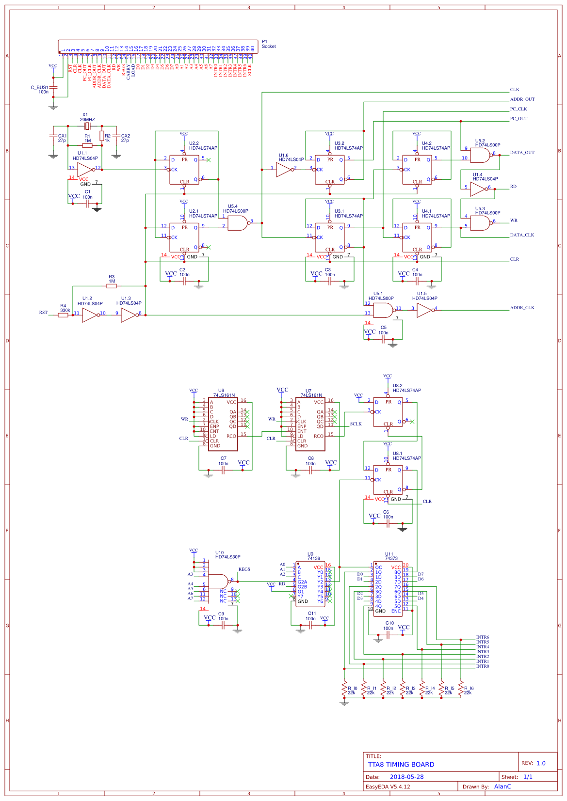
I have added a Timer to the Timing Board. The timer triggers an interrupt every 256 instructions. If I use a 20 MHz crystal fro a 10 MHz clock (the max!), then an interrupt is triggered at 9766 Hz which is close enough to 9600 baud for a serial interface (for later).
I have also moved the interrupt register onto the timing board to free up a bus line for a Serial Clock (SCLK). The timer uses INTR7 (the highest priority) which is not longer accessable from the bus.
Here is the EasyEDA Schematic:

Only three boards remain:
- PC
- ALU
- Memory
Then possibly a Serial Board.
---
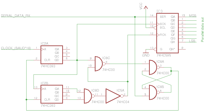
Modified the timing board for 16x the baud clock as I found a schematic for serial input:

(Source: http://digitarworld.uw.hu/circuits.html).
AlanX
 agp.cooper
Discussions
Become a Hackaday.io Member
Create an account to leave a comment. Already have an account? Log In.