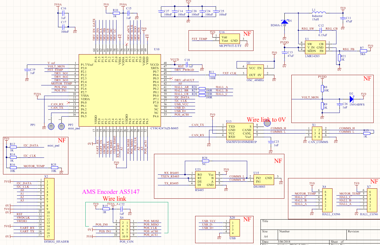
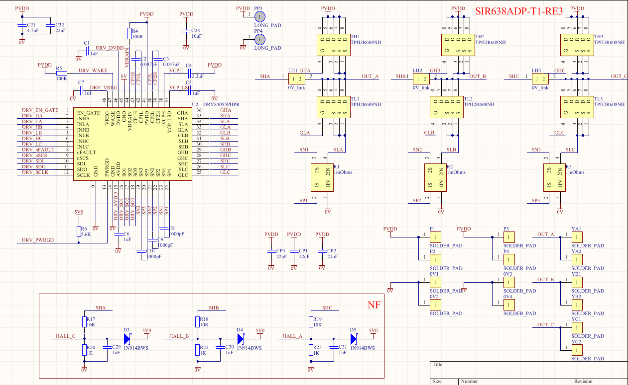
From everything that was learnt from the hardware development a real / custom actuator had to be developed. After some research the best/easiest solution for me was the 3-Phase driver DRV8305 paired with 6x N-MOSFETs and the PSOC4 Processor.
Hardware for the Second Controller
- Custom 4 Layer PCB 47mmx45mm
- PSOC4 CY8C4247AZI-L485 ARM Cortex-M0 32-bit Processor with Programmable Analog Block and Programmable Digital Blocks
- DRV8305 MOSFET Driver with integrated Current Sense Amplifers, SPI and PWM Control
- 6x N-MOSFETs R-on-typical @ 0.7mOhms 40V
- 3x 1mOhms Current Sense Resistors
- CAN Transceiver
- 25MHz Oscillator
- LMR14206 Step Down Regulator
- Optional (un-populated) - RS485, FET Temp Sensor, USB, Hall effect input, Sensorless operation

Brushless Controller 2.0
There is not much to say about this controller. All components were "wired" up as per their datasheets. As the two main IC's have a lot of integrated components inside there is not much interconnects required.

The angle of the motor and the joint is read by the AS5147s via SPI. PSOC4 uses PID to determine the required joint position and uses Field Orientation Control from motor angle to calculate 3 Sinusoidal values. These Sinusoidal values are converted to PWM signals to drive the 3-phase Driver. This intern drives the 6x N-MOSFETS to power the Brushless Motor. Control of the Actuator is done by CAN.
As the board was soldered by hand, the SPI link between PSOC4 and the DRV8305 helped to to pick up dry-joints and short-circuits on the MOSFETs, Current Sense Resistors and some DRV8305 pins. It had many fault and error registers which points directly to the bad connection.


The Schematic and PCB has been uploaded to the "file page".
 Paul Gould
Discussions
Become a Hackaday.io Member
Create an account to leave a comment. Already have an account? Log In.
I didn't want to calibrate/reference the joint very time the system power up. There is only a small amount of backlash on the gearbox. Some joints have three encoders. (motor, joint, Series Elastic Actuator).
I'm not doing FOC with current feedback yet. It does vector control via voltage. FOC timing and calculation are hard on a smallish processor.
Are you sure? yes | no
Hey Paul !
May I ask why you use two encoders instead of one. Is there too much mechanical play in your gearbox to use the encoder feedback from the sensor mounted on the cycloidal gear output ?
How much play do you have in your reducer? Because according to TI's instaspin tutorial, it is possibly to have an efficient FOC algorithm with as much as 4 degrees error on the encoder feedback. I would believe that you're reducer don't have that much backlash.
Very fascinating project by the way ! Craving for more ! :)
Are you sure? yes | no