Hoverbot is easy to assemble using basic hand tools and repurposed consumer hardware. This blog post details one possible way to assemble Hoverbot, but it can be built using whatever materials you have handy, as long as you have the necessary core components (a hoverboard and a Raspberry Pi).
Physical assembly
Disassemble the hoverboard
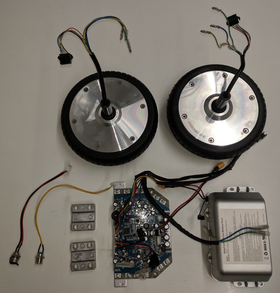
Save the motor controller, motors, motor mount plates, power switch, charge port, and battery.
Case removal
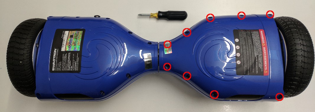
From the bottom of the hoverboard, remove the 9 Philips head screws from the side without the power button/charge connector. In order to remove the plastic case, you'll have to disconnect the LED cable from the gyro board. Set aside the plastic case.
Battery disconnect
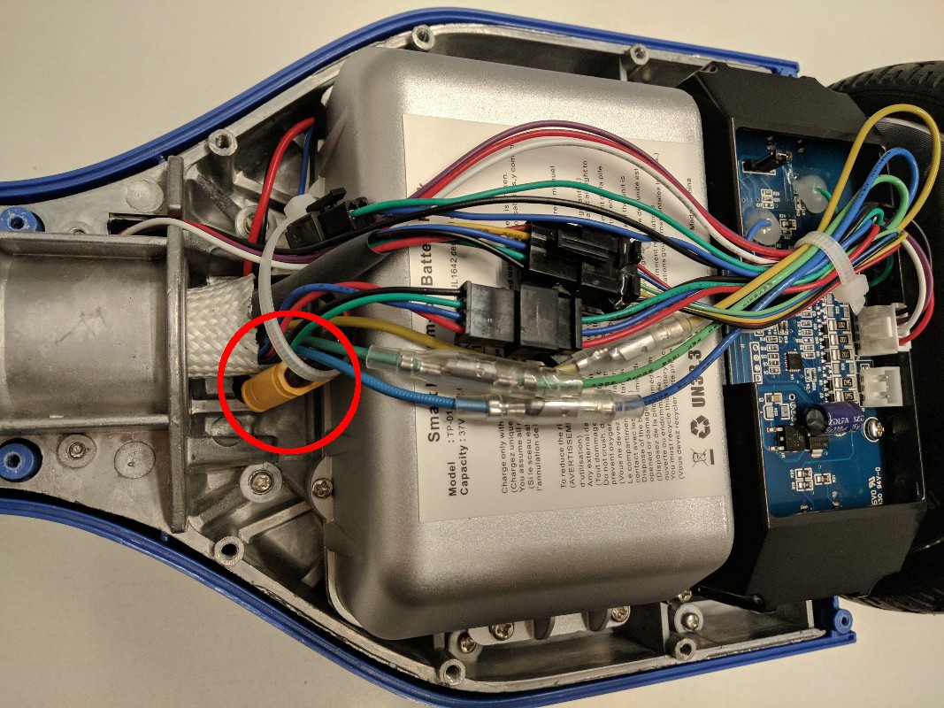
Disconnect the yellow battery connector circled in red below. You can remove the zip tie holding the cable bundle together.
Motor controller removal
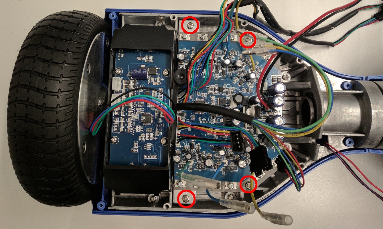
Remove the 9 Philips head screws holding the other half of the bottom case and disconnect the power button, charge connector, and LED panel. Disconnect all connectors on the motor controller - including the connectors on the opposite side - and fish the cables through the center tube. Then remove the 4 Philips head screws - circled in red in the image below - that hold the motor controller and heat sink to the hoverboard body. This might be a good time to program the new firmware on the motor controller as it is easy to test that it is working when the wheels are still connected to the hoverboard body.
Battery removal
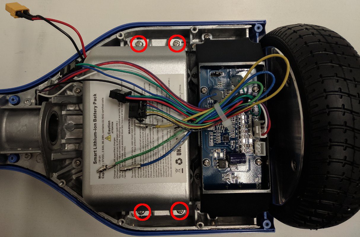
Remove the 4 Philips head screws holding the battery to the hoverboard body. You can cut the zip tie bundling the cables and may need to remove a secondary battery connector as well. If your battery is not in a hard case as shown below, it will likely be held down by double-sided adhesive tape underneath. If this is the case, you'll need to very carefully pry it off the hoverboard body. WARNING: DO NOT USE SHARP OR HARD IMPLEMENTS TO PRY ON THE BATTERY. DO NOT PUNCTURE THE BATTERY.
Wheel removal
Remove the 4 Philips head screws holding the gyro board mounts on both sides of the hoverboard and set the gyro boards aside. Then remove the 6mm Allen head screws holding the wheels to the hoverboard body. Be sure to save the square metal mounting plates for the wheels.

Switch removal
Remove the power switch and charge connector from the case half. You may need to remove some glue that is on the retaining nuts. Make sure to save the retaining nuts.
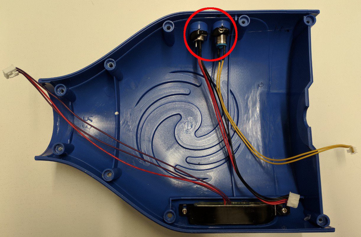
Gathered parts
Now that you've disassembled the hoverboard, you should be left with the collection of parts below.
Build a base support
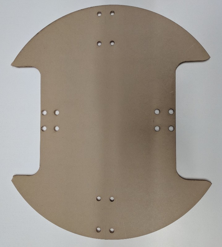
The base of the IKEA table isn't quite strong enough to support heavy loads after it's been cut to make room for the wheels, so you'll need to make a support for it. Print out the base support template pdf and use a drill and a jigsaw to cut a support from thin plywood. Alternatively, you can laser cut a base support from 0.25" acrylic (base support template dxf).
Mark where to cut the base
When referring to the IKEA table sections the orange or teal sections in the image below will be the "tallest" sections, the gray will be the "medium", and the yellow will be the "thinnest".
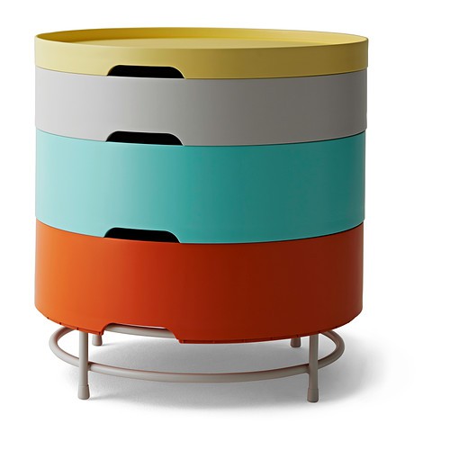
To mount the wheels and casters, you're going to cut some holes in this lovely piece of quality Swedish furniture. Use the base support itself (or the template you printed out) and a sharpie to mark the cuts on the bottom of the tallest section.
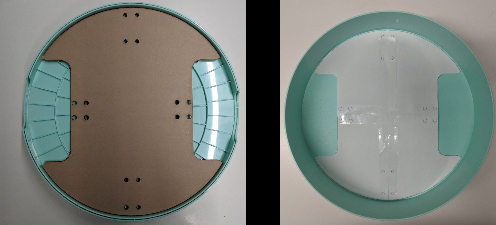
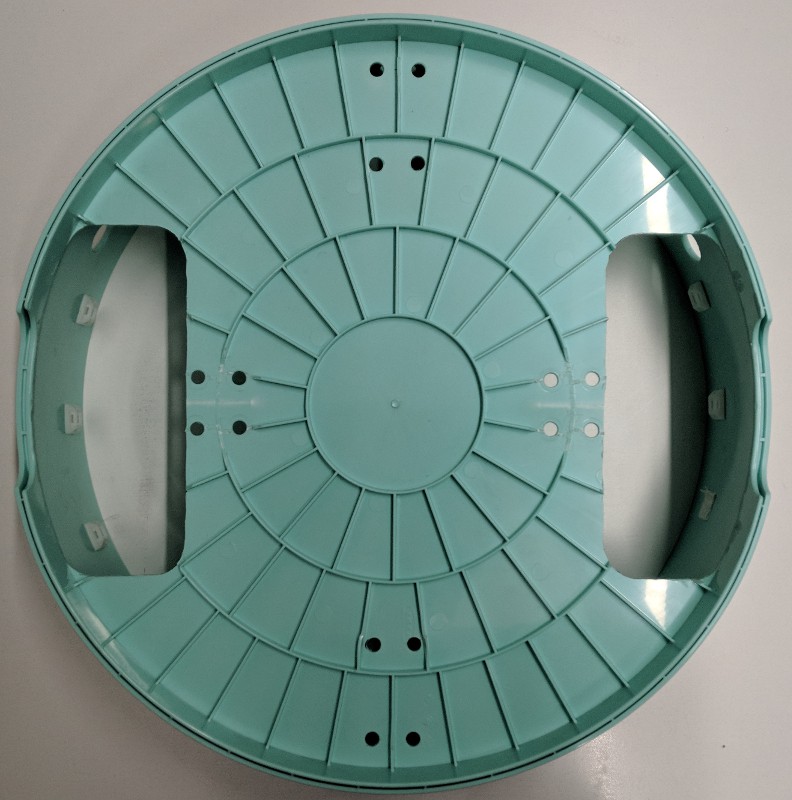
Actually cut the marked holes
Using a Dremel with a cutoff wheel, cut out the wheel holes you just marked. Use a drill to cut the bolt holes for the casters. Please wear safety glasses - or better yet a face shield! - while preforming this step. Spinny things are dangerous!
Drill holes in the side wall
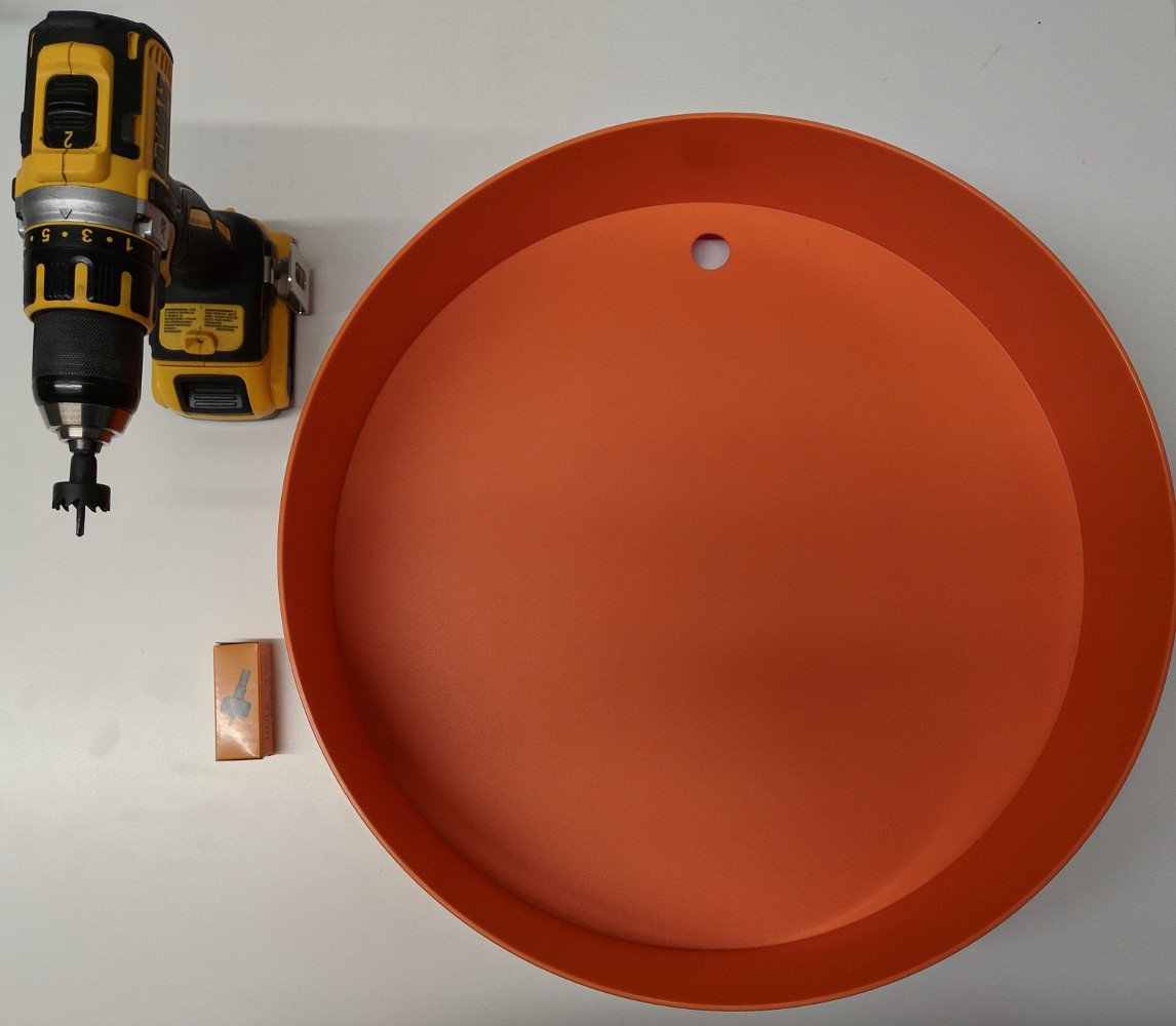
Drill the holes in the side walls of the tallest section for mounting the sonar sensors (use the hole saw provided with the automotive backup sensor kit). Note that the wheels have already been installed in the image below, but it is recommended that you drill the holes before installing anything.
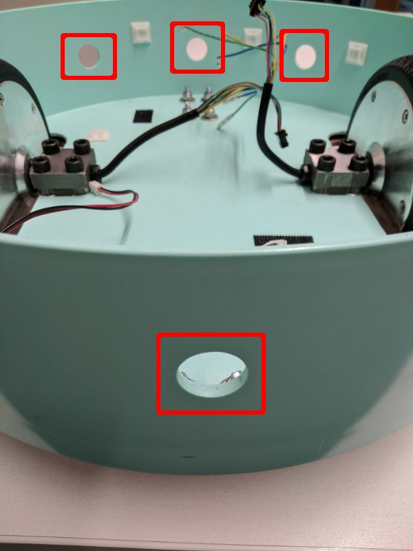
Drill holes on the side walls of the tallest section for mounting the power switches and the charge connector.
Mount motors
To mount the wheels, you'll need the following hardware:
- 8: Bolts (M8x35)
- 2: Mount plates (from hoverboard)
- 4: Side spacers 0.30" (can be laser cut or just stacked washers) TODO add dxf for laser cut spacer
- 2: Bottom spacers ~0.25" (can be laser cut or just stacked washers) TODO add dxf for laser cut spacer
- 16: M8 washers
- 8: M8 nuts (nyloc preferred)
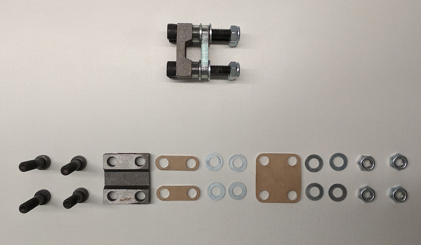
Assemble 4 bolts, a mount plate, and 2 side spacers. (In this case, an acrylic piece was used with 1 additional washer per bolt).
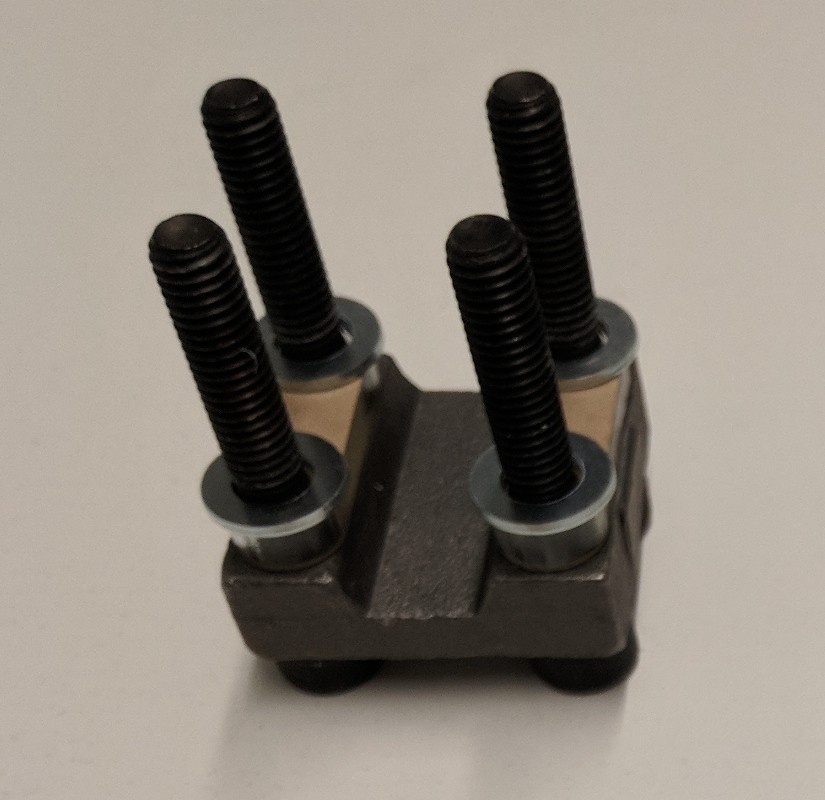
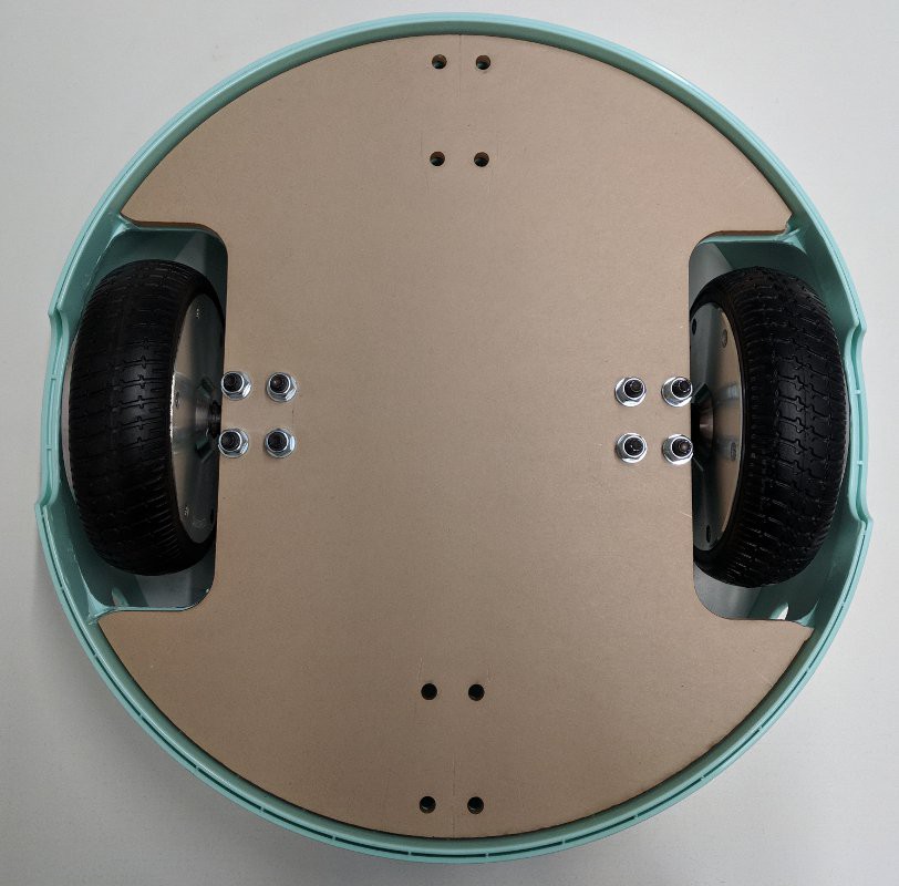
Slide the bottom spacer between the mount plate and the IKEA table section such that the holes line up. Then place the flat of the motor shaft on the flat of the mount plate and bolt in place.

Tighten the bolts and repeat for the other side.
Mount the casters
You'll need:
- 8 bolts (M6x30 or 1/4")
- 8 washers
- 8 nyloc nuts
- 2 casters
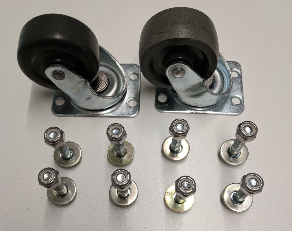
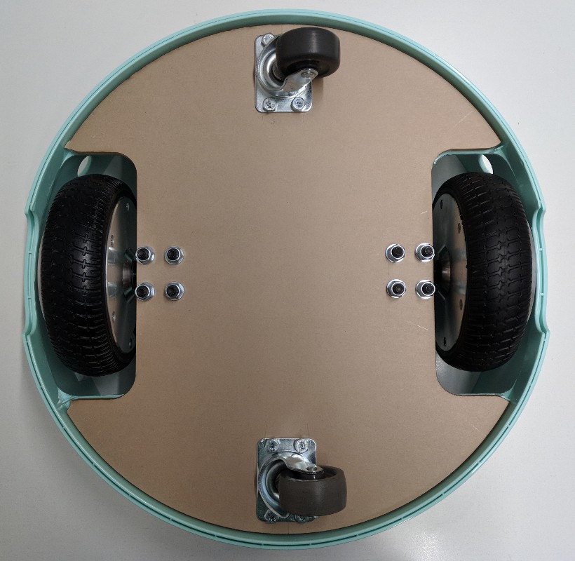
Mount the casters. The washers should go under the nuts on the top side of the robot.
Drill cable pass though hole
Drill a hole in the bottom of the medium IKEA table section using the hole saw.
Electrical assembly
Master power switch
In this assembly, all of the systems will be powered by the hoverboard battery for ease of charging and setup. As a safety feature you can add a physical power switch between the battery and everything else. Fortunately, the hoverboard battery uses a common remote control hobby connector (XT60) for which you can find an off the shelf switch.
12V system
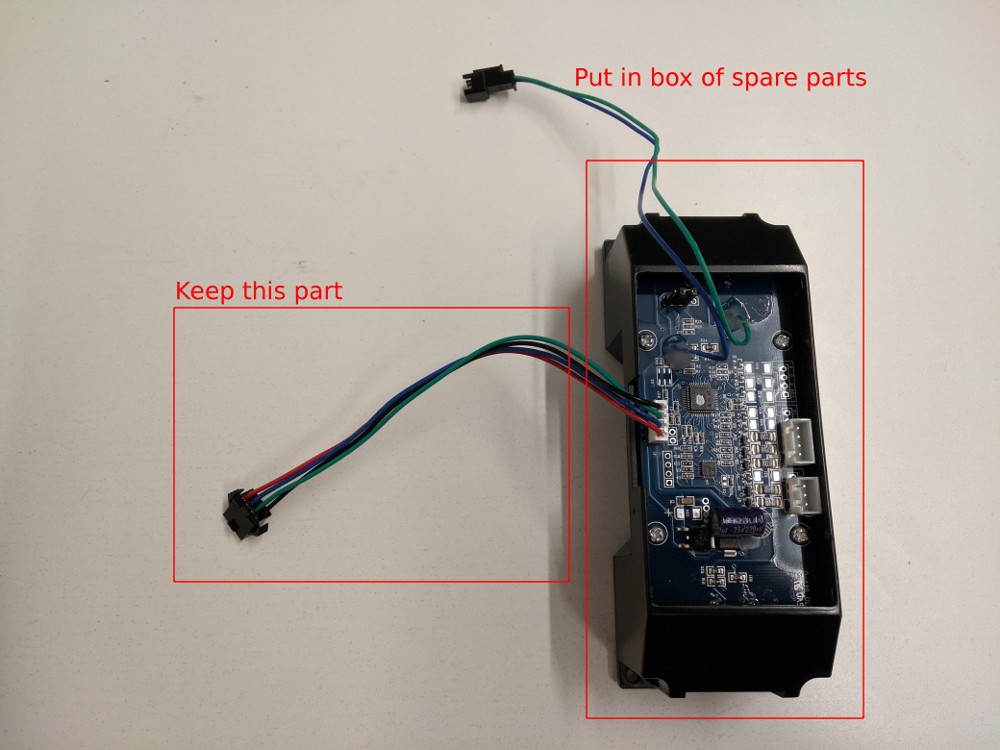
The hoverboard motor controller has a 12V supply that can be used to power the sonar box. This 12V supply is most easily connected by using the wire that previously powered the hoverboard gyro boards. As you won't be using the gyro boards, you can cut the wire and connector (marked below) from the gyro boards and solder the backup sensor power wires to the cut off cable.
5V system
The hoverboard motor controller also has a 5V supply that is used to power the hall effect sensors. Unfortunately that supply does not provide enough current for either the Raspberry Pi or the LED strip, so you'll have to find another 5V power source.
To provide a higher current 5V source, an automotive USB charger can be repurposed to draw power from the hoverboard motor controller 12V supply. The USB port is quite convenient for the Raspberry Pi as it is powered via a USB connection :) It is less convenient for the LED strip because you'll need to solder the LED power wires to the 5V output of the automotive USB charger. Alternatively you can cut open a USB cable and solder to the LED power and ground lines. Be sure it is a USB cable with thicker conductors - power-only USB cables are usually good for this.
(TODO add pictures of this)
Sonar data connetion
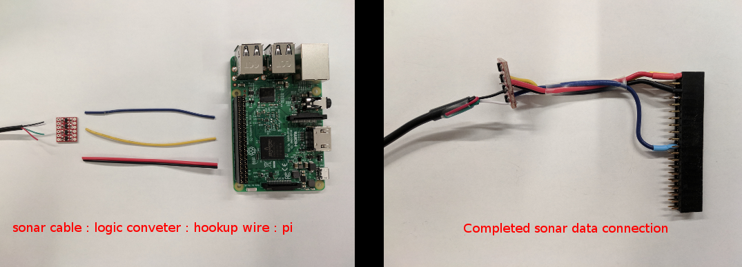
The sonar data is output at a 5V logic level and the Raspberry Pi is only tolerant of 3.3V on the input pins. You can either use a pair of resistors as a voltage divider or use a logic level converter to step down the 5V to 3.3V. The stepped down signal should be connected to the MISO pin of the Raspberry Pi which is pin 21 on the Raspberry Pi GPIO header. The sonar display wires should be connected as you determined them in the project log on reverse engineering automotive backup sensors. Do not trust the sonar display wire color as it may not be the same as shown here. Note the two unused (5V and Buzzer) sonar display wires are folded over and heatshrinked (heatshrunk?) to protect from shorts.
Hoverboard serial connection
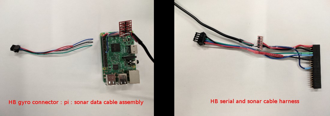
The hoverboard motor controller uses 3.3V serial, which is a perfect match for the Pi. Using the second gyro board connector, attach the blue cable to the Pi serial Rx (pin 10) and the green cable to the Pi serial Tx (pin 8). With the flat edge of the motor controller facing away from you, this gyro connector should plug into the leftmost connector. It is worth double checking that the wire order on the leftmost gyro connector is - from outboard to inboard / left to right - Black, Green, Blue, Red. Note that the red power wire on the gyro connector is folded over and heatshrinked to keep it from shorting on anything.
LED data connection
The LED strip data lines are setup to take a 5V signal but they can be connected directly to the Pi, as the 3.3V signal the Pi outputs should be enough to drive them. The DIN (data in) line on the LED strip should connect to the Pi MOSI output which is pin 19. The CIN (clock in) line on the LED strip should connect to the Pi SCLK output which is pin 21. If you have trouble with the lights and you are using a logic level converter for the sonar input, you can use the same converter to step up the Pi's 3.3V signal to 5V.
If you buy a full meter of LED strip it should come with connectors on both ends. You can cut off the output end (the one the arrows on the LED strip point to) and use it to connect to your Pi headers. Note that the red power wire is again heatshrinked to prevent it from shorting (power is supplied to the LED from the 5V connection as noted above).
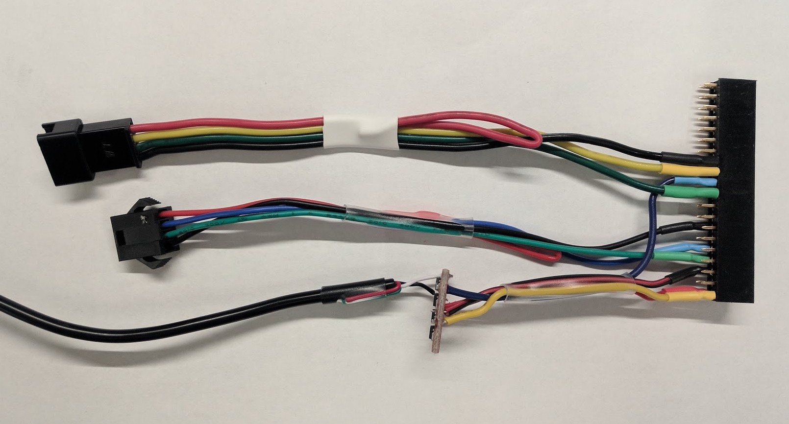
Hoverboard power and charge
The power switch and charge connector for the hoverboard motor controller will connect as they were in the hoverboard. If you drilled holes for these in the side of your IKEA table, be sure to feed the connectors though from the outside before plugging them in.

Sonar sensor connections
Connect the sonar sensors to the sonar sensor hub in this order:
- Left sensor: port A
- Center sensor: port B
- Right sensor: port C
- Rear sensor: port D
Be sure to feed the cables though the holes in the side of the IKEA table before plugging them in to the sonar sensor hub.
Electronics placement
Using double-sided tape (or sticky Velcro) and zip ties, mount all of your components to the bottom of the tallest IKEA table section.
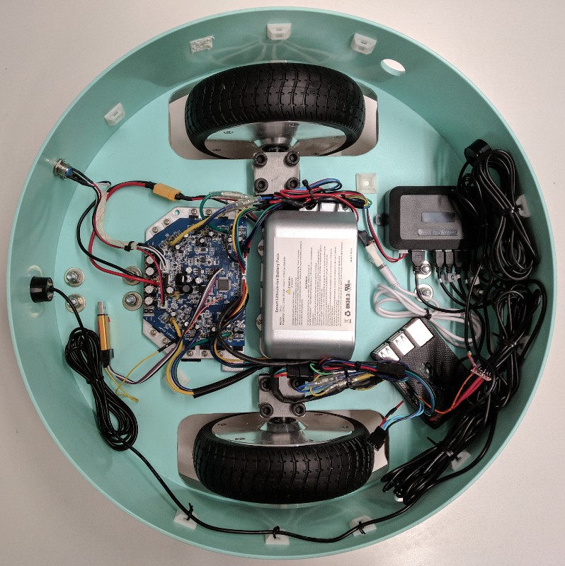
Not shown above: web camera, LED strip, speaker
LED strip and diffuser installation
Place your plastic diffuser inside the medium IKEA table section. Be sure the diffuser is not pushed all the way to the edge such that you can snuggly place the thinnest section on top of it. You can use hot glue to hold it in place. Snake the LED strip cables though the hole in the base of the medium IKEA table section and connect them to the harness you built for the Pi.
TODO add pictures for LED and LED diffuser installation
Web camera installation
The web camera connects directly to the Pi via USB. The cable can be snaked though the hole that the LED connectors are using in the base of the medium IKEA table section. You can then either use the hole saw to add a hole to the thinnest IKEA table section or route the cable out the handle. Given the variety of web cameras, a mounting solution will not be covered here. It is likely easiest to attach it to the thinnest IKEA table section using double-sided tape.
Speaker installation
The speaker can be pretty much any off the shelf battery powered speaker with a 3.5mm line-in headphone plug. The location of the speaker is not particularly critical as long as you can hear it. Double-sided tape is perfectly acceptable for mounting. The line-in plug of the speaker will connect to the headphone jack on the Pi
Celebrate! You've just assembled a hoverbot! YAY! Everybody dance!!!
 Isabelle Simova
Discussions
Become a Hackaday.io Member
Create an account to leave a comment. Already have an account? Log In.