Close
0%
0%

Hoverbot

A low cost, modular, hoverboard-based, open source robot

Similar projects worth following
A low cost, extensible robot built from repurposed consumer products and modern software tools.

Most modern robots fall into one of two categories: professional grade or hobbyist level. Professional robots are generally built for a single purpose (e.g. industrial manufacturing, vacuuming, security) and cannot be easily adapted for other applications. Hobbyist level robots are often built for flexibility and extensibility but the hardware required to make them robust and reliable is expensive.

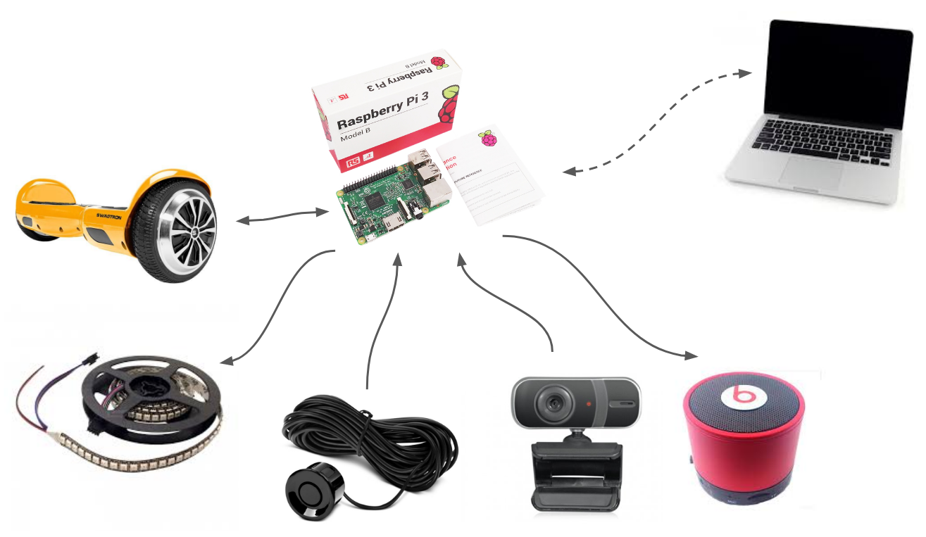
Hoverbot bridges the gap between the two categories by repurposing existing cheap consumer products and leveraging modern software tools. The result is a moderately priced (~$250), extensible, functional robot. 

This project is broken down into a collection of modules that can be either used in combination to create your own Hoverbot or used individually as components in other projects. Hoverbot modules:

View all 19 components

  • Programming Hoverbot

    Isabelle Simova05/10/2018 at 23:22 0 comments

    Installation

    Follow the instructions on the Hoverbot GitHub to download and setup the Hoverbot software on your Raspberry Pi.

    Default behavior

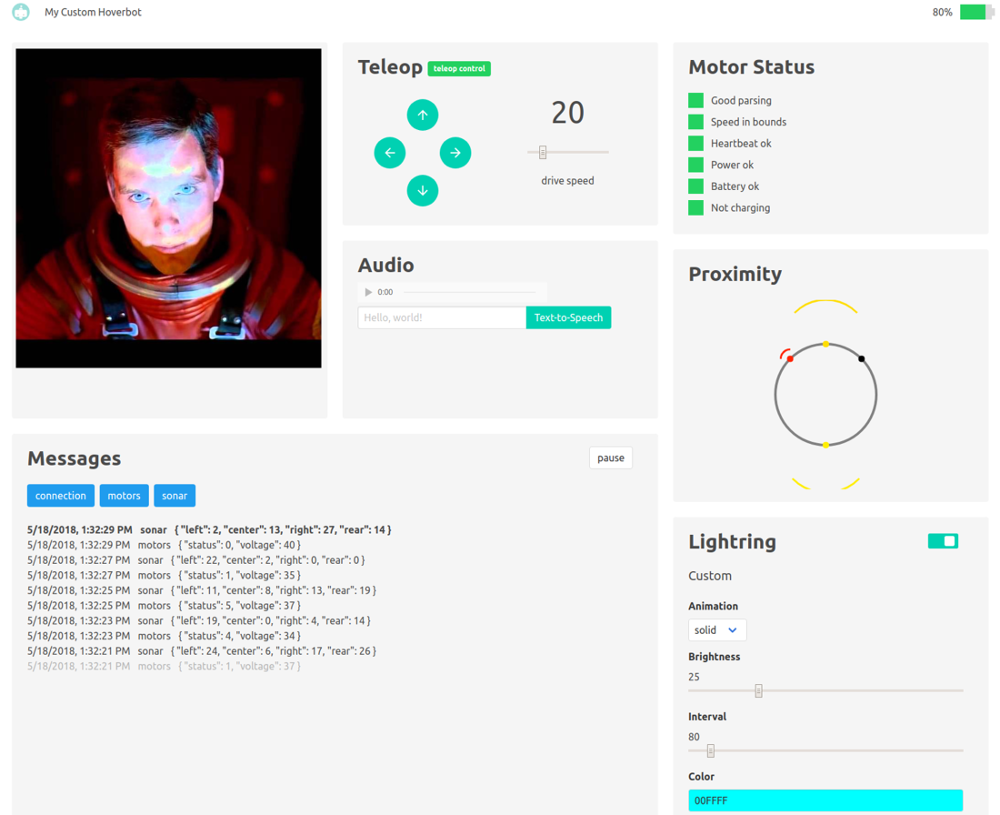
    The Hoverbot software is a Node.js application. The default code enables control of the robot via a teleoperation interface, shown below. The interface includes a live camera stream, a "live" audio stream, a directional control pad, a text-to-speech input box, LED strip controls, a sonar sensor visualization, a health status for the hoverboard motors, and a message log. The interface is a useful debugging tool and a starting point for building more interesting applications.

    Why javascript?

    Most robots are effectively just collections of connected sensors and actuators that broadcast data and listen for particular events to take action on, which makes the event-driven architecture of Node.js a great framework for Hoverbot. Node.js' package manager, npm, is another reason to use JavaScript due to its engaged community and large ecosystem of open source libraries. Hoverbot leverages several npm packages, including serialport and pi-spi.

    Extensible

    The Hoverbot code is written to be extensible. All data producers emit named events to which you can easily add custom listeners. Take a look at the event listeners in customHoverbot.js as an example.

    You can easily extend the current sonar data listener to do more than just broadcast data. Presuming you're interested in taking the squishy human out of the loop, turning this teleoperation application into something autonomous, you could add some logic to let the robot drive on its own, using the sonar data to avoid obstacles. It might look something like this:

    // This is a naive implementation for demonstration purposes!
    // BE CAREFUL, THE HOVERBOT MAY NOW WANDER AS SOON AS IT BOOTS!
    
    // Listen for spi to emit sonar data, relay data via broadcast for the server to send to the client
    hoverbot.spi.on('sonar', (data) => {  
      if (data.center > 5) { // Nothing in front? go forward
        hoverbot.motors.move(-20, -20);
      } else if (data.left > 5){ // Side clear? turn that way
        hoverbot.motors.move(-20, 0);
      } else if (data.right > 5){ // Other side clear? turn that way
        hoverbot.motors.move(-20, 0);
      } else if (data.rear > 5){ // Only rear clear? back up
        hoverbot.motors.move(20, 20);
      } else { // No direction clear at all? STOP!
        hoverbot.motors.move(0, 0);
      }
    });
    

    Be sure to read the documentation in the github repo for more detail, and feel free to submit a pull request when you're done creating something awesome!

  • Assembling Hoverbot

    Isabelle Simova05/10/2018 at 23:18 0 comments

    Hoverbot is easy to assemble using basic hand tools and repurposed consumer hardware. This blog post details one possible way to assemble Hoverbot, but it can be built using whatever materials you have handy, as long as you have the necessary core components (a hoverboard and a Raspberry Pi).

    Physical assembly

    Disassemble the hoverboard 

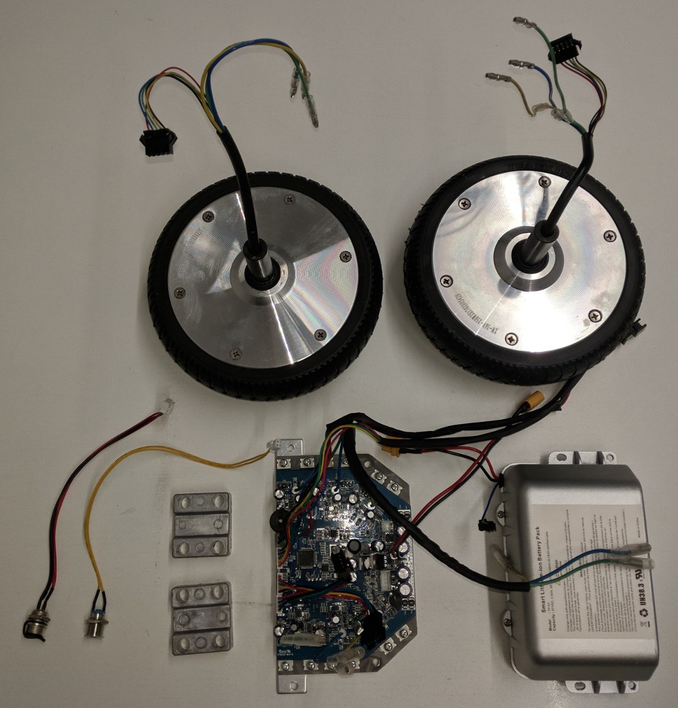
    Save the motor controller, motors, motor mount plates, power switch, charge port, and battery.

    Case removal

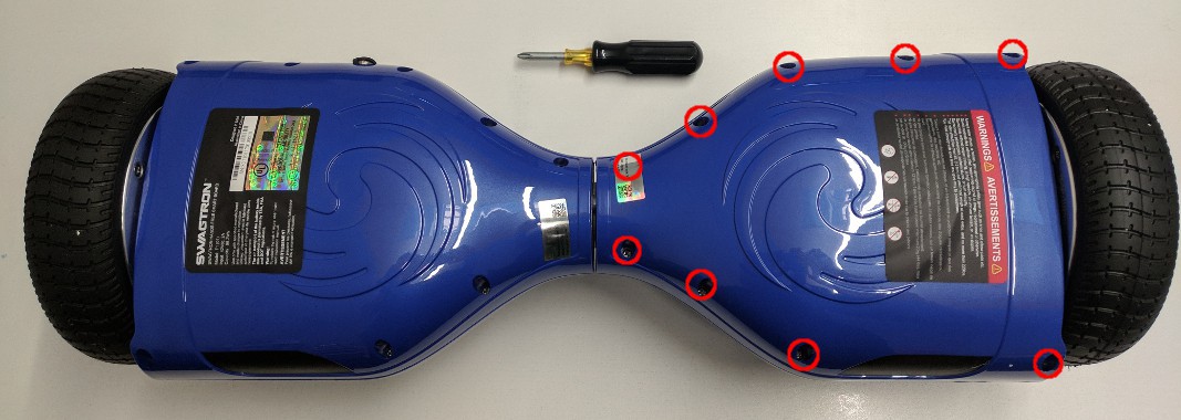
    From the bottom of the hoverboard, remove the 9 Philips head screws from the side without the power button/charge connector. In order to remove the plastic case, you'll have to disconnect the LED cable from the gyro board. Set aside the plastic case.

    Battery disconnect

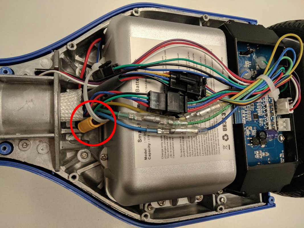
    Disconnect the yellow battery connector circled in red below. You can remove the zip tie holding the cable bundle together.


    Motor controller removal

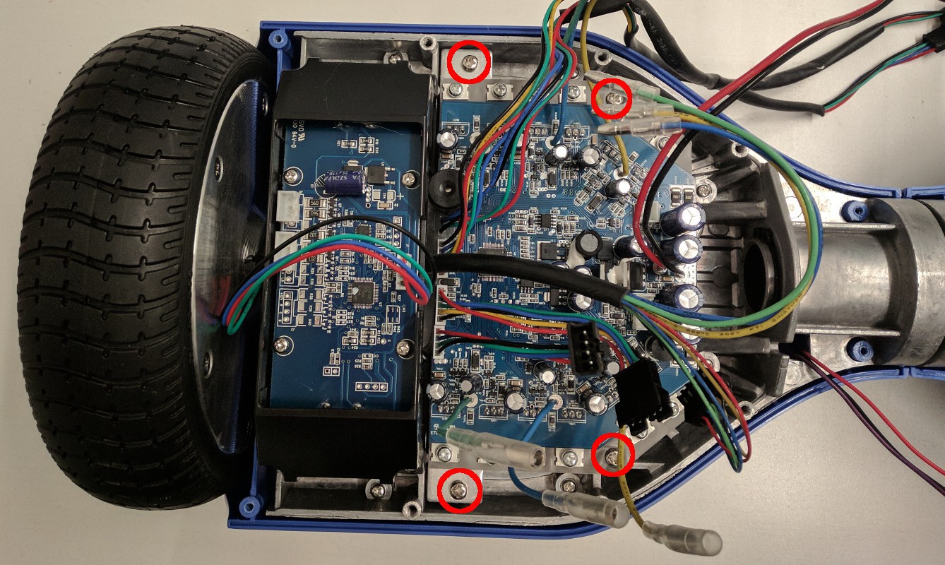
    Remove the 9 Philips head screws holding the other half of the bottom case and disconnect the power button, charge connector, and LED panel. Disconnect all connectors on the motor controller - including the connectors on the opposite side - and fish the cables through the center tube. Then remove the 4 Philips head screws - circled in red in the image below - that hold the motor controller and heat sink to the hoverboard body. This might be a good time to program the new firmware on the motor controller as it is easy to test that it is working when the wheels are still connected to the hoverboard body.

    Battery removal

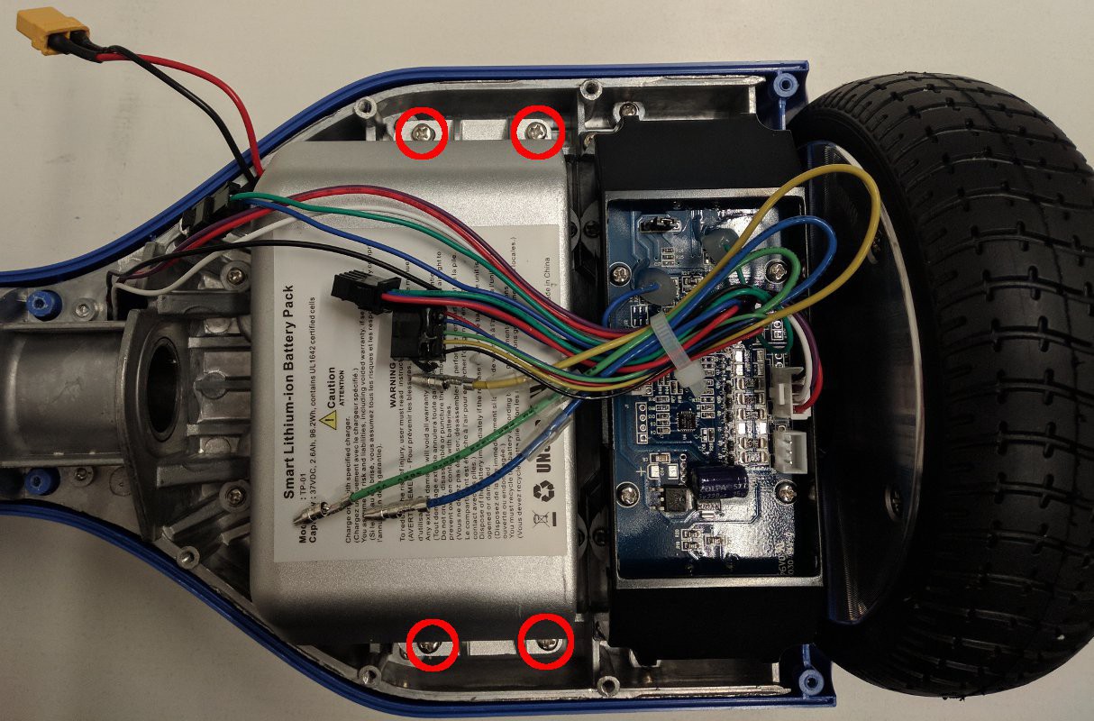
    Remove the 4 Philips head screws holding the battery to the hoverboard body. You can cut the zip tie bundling the cables and may need to remove a secondary battery connector as well. If your battery is not in a hard case as shown below, it will likely be held down by double-sided adhesive tape underneath. If this is the case, you'll need to very carefully pry it off the hoverboard body. WARNING: DO NOT USE SHARP OR HARD IMPLEMENTS TO PRY ON THE BATTERY. DO NOT PUNCTURE THE BATTERY.

    Wheel removal

    Remove the 4 Philips head screws holding the gyro board mounts on both sides of the hoverboard and set the gyro boards aside. Then remove the 6mm Allen head screws holding the wheels to the hoverboard body. Be sure to save the square metal mounting plates for the wheels.

    Switch removal

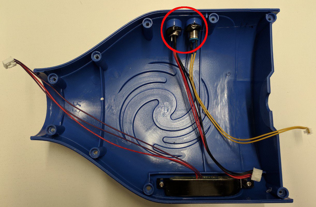
    Remove the power switch and charge connector from the case half. You may need to remove some glue that is on the retaining nuts. Make sure to save the retaining nuts.

    Gathered parts

    Now that you've disassembled the hoverboard, you should be left with the collection of parts below.

    Build a base support

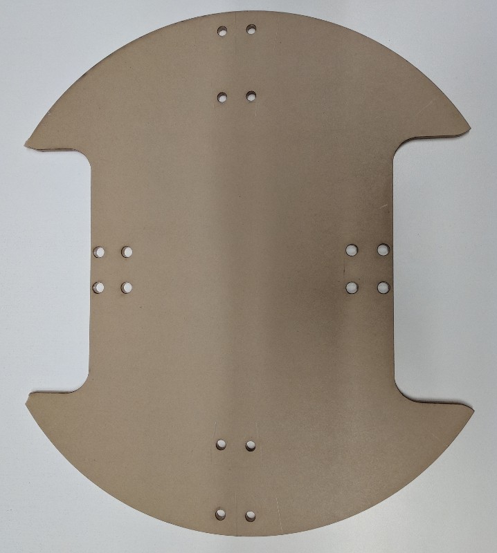
    The base of the IKEA table isn't quite strong enough to support heavy loads after it's been cut to make room for the wheels, so you'll need to make a support for it. Print out the base support template pdf and use a drill and a jigsaw to cut a support from thin plywood. Alternatively, you can laser cut a base support from 0.25" acrylic (base support template dxf).

    Mark where to cut the base

    ... Read more »

  • Reverse engineering automotive backup sensors

    Isabelle Simova05/10/2018 at 23:17 0 comments

    Aftermarket automotive backup sensors are cheap and ubiquitous. They use transducers to produce an inaudible ping and receive the reflected response - the time it takes for the ping to return indicates how far away any potential obstacles may be, which is shown on some kind of dash-mounted display. These transducers are very similar to those found in the maxbotix ultrasonic proximity sensor but are significantly cheaper. So what's the difference? The automotive kits don't include the fancy USB interface to programmatically read the data. However, with a little bit of tinkering you can intercept the data signal connected to the dash display and read the data just the same.

    Automotive backup sensor kit

    The kit

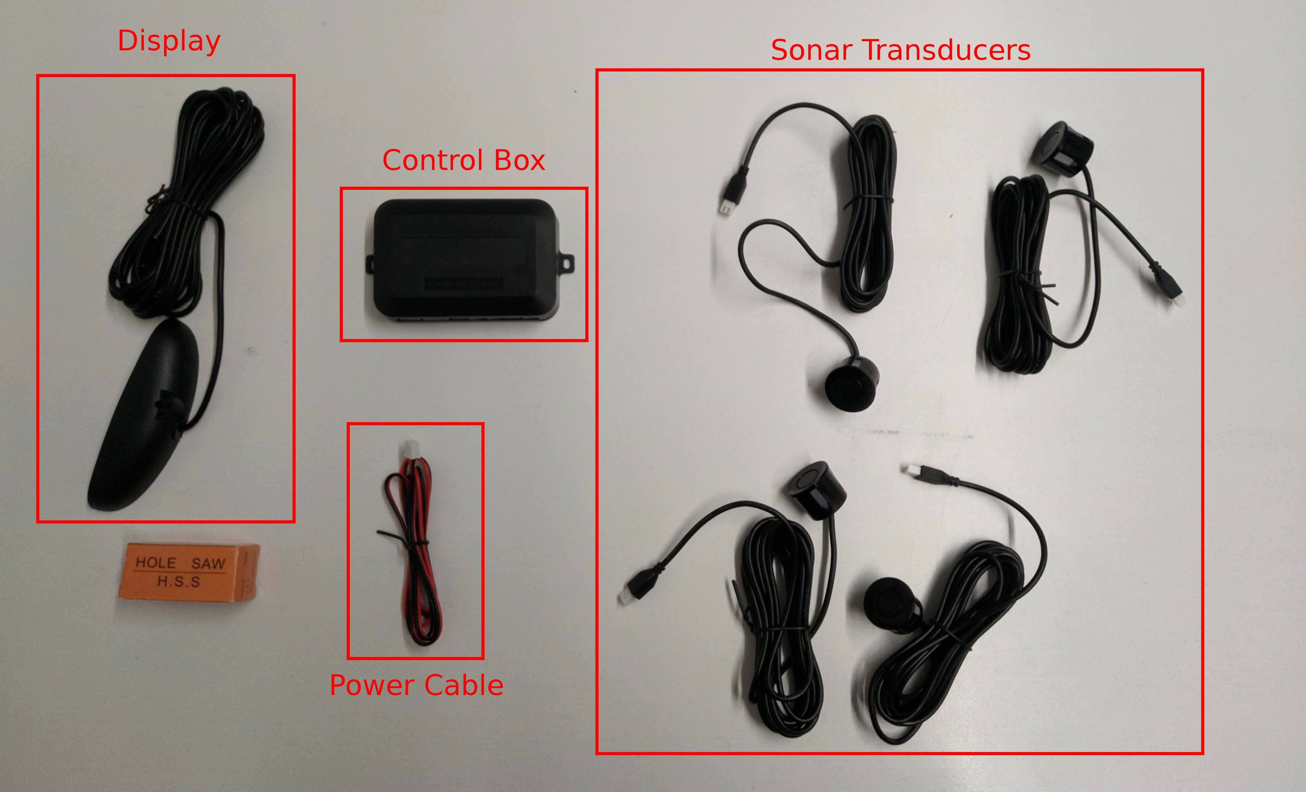
    Most backup sensor kits include 4 transducers, a control box, a power cable, a display, and a hole saw. The control box generates the pings for the transducers, listens for the ping response time from the transducers, interprets the response times as distances, and finally aggregates those distances to send to the display. 

    Show me the data!

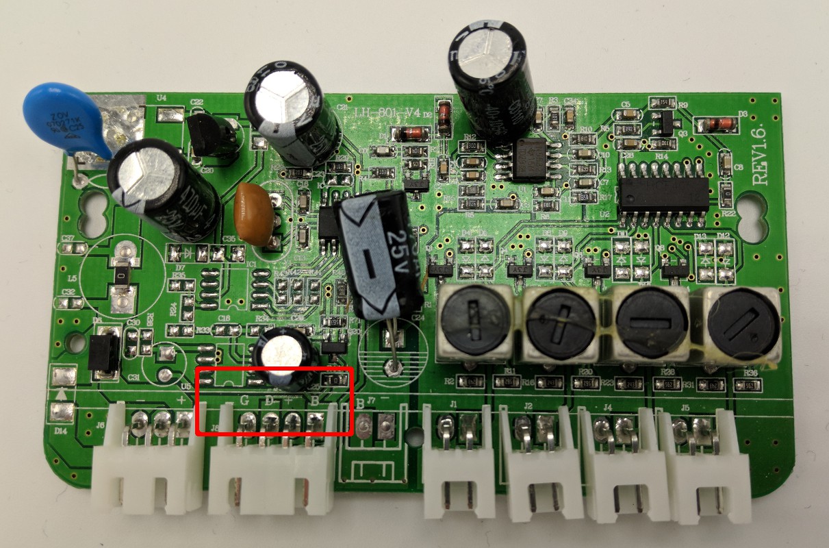
    You can intercept the aggregated distance data by connecting a microcontroller to the display cable, but you'll first need to identify the data pin by taking a look inside the control box. Open the control box by removing the 2 screws in the bottom of the case. If you are lucky, the silkscreen on the board will include a label for each pin as shown in the red box in the image below. G is for ground, D is for data, + is for display power. You might also see a B for buzzer, but not all kits have it.

    If you're not so lucky, your board may be completely blank. That's a bummer, but it's not a blocker and you can still figure it out. First, connect the power cable to the control box and a 12v supply. Make sure nothing but the power supply is plugged into the control box. Carefully use a multimeter to check for voltage between ground and each of the display cable pins. If your board has 3 pins one of them should have no voltage - this is ground. Another pin should have 5v - this is the display power. Finally, one should have a low, fluctuating voltage - that's the data pin. If your board has 4 display pins, there will also be a second pin with no voltage, one of which is the buzzer and the other is ground. Change your mulitmeter to measure resistance and compare the two 0 voltage pins with ground. The one with no connection (infinite resistance) to ground is the buzzer. At this point you might want to label the pins so you don't have to do it again. 

    Understanding the data

    If you just want to get the data and move on, you can skip ahead to the next section. If you're compulsively curious about how things work, read on.

    Using a Saleae logic analyzer connected between the data pin and ground, you can observe the signals between the control box and the display. You might notice that the board's data line is nominally low and the width of the high pulses changes as you move things around in front of the sensors.

    After sufficient arm waving and some strange looks from people in your vicinity, you might start to notice a pattern; there is a consistent 2 ms high pulse followed by a 0.01 ms high pulse, which is then followed by 32 more high pulses of either 0.01 ms or 0.02 ms. At this point you might take a wild guess that a 0.01 ms high pulse represents a 0 and a 0.02 ms high pulse represents a 1.

    The 2 ms...

    Read more »

  • Reprogramming hoverboards for robots

    Isabelle Simova05/10/2018 at 23:16 1 comment

    Why hoverboards?

    There are plenty of cheap small robots available and there are plenty of expensive large robots available, but it is hard to find cheap robots that can move a reasonable amount of weight. And what good is a robot if it can't move anything around? Hoverboards, as it turns out, include a convenient collection of components that can be used to power and drive a cheap, capable robot.

    • High torque, direct drive, brushless motors (with large diameter wheels)
    • Motor controller
    • High capacity battery
    • Battery charger

    Great! Lets make a hoverboard robot

    The hoverboard motor controller is programmed for a human controlled, self-balancing system. This system consists of two gyroscope sensors feeding data to the motor controller, which responds by moving the motors to keep the gyros "flat". This is what keeps the human upright most of the time.

    But we want to replace the squishy human with a cold unfeeling robot. Some people have already shown how to remove the human from the hoverboard control loop by sending fake gyro data. These examples include Low cost two wheels drive - hoverboard hack and How I hacked the Self Balancing Scooter. Unfortunately the original firmware is written such that it will increase the speed of the wheels if it is fed a constant gyro angle. This behavior makes it challenging to move the motors at a constant speed.

    Well, what now then?

    Fortunately most hoverboard motor controllers use a common micro-controller (STM32F103 or a clone) that can be reprogrammed. We can write new firmware to use a custom communication protocol to drive the motors in a way that is betted suited for robotics applications.

    Check your hoverboard motor controller for compatibility with available firmware

    There are at least two different motor controllers in common use by hoverboard manufacturers; one with a single motor controller that drives both wheels and another with a controller for each wheel and a data connection between them. This project currently includes custom firmware compatible with the single board controller. See this google doc for further instructions on identifying different hoverboard motor controllers.

    Remove the motor controller and attach programming header pins

    Before you can reprogram the motor controller you'll need to first remove it from the hoverboard (for detailed instructions see the physical assembly blog post). You'll also need to remove the motor controller board from the aluminum heat sink plate - it is attached via the remaining screws through the transistors.

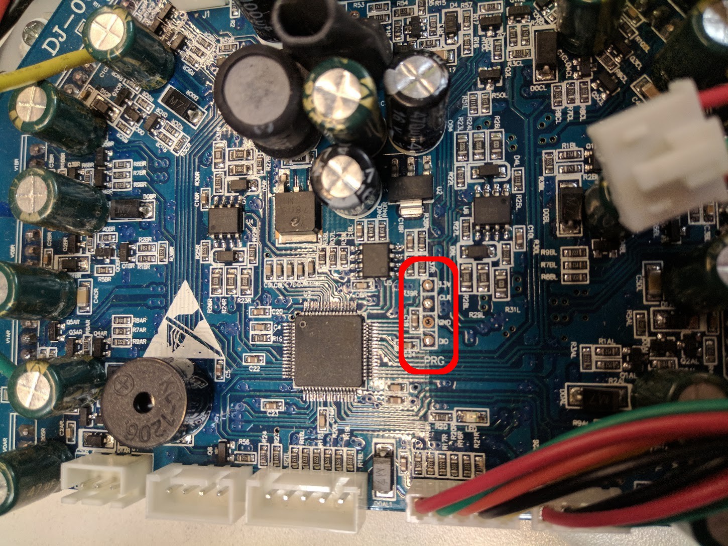
    Once the motor controller is removed, you'll need to solder the programming header pins to the board - don't worry, it's not very hard. Some motor controllers have the programming header pin holes filled with solder (as shown in the picture above). If they are filled you will need to clean them out using either a solder sucker or solder-wick. Once the holes are clean, solder four regular 0.1" spacing header pins to the board.

    (Though not strictly necessary, you can breakout the STM32F103's reset pin for more reliable programming. You can still reprogram the board without this step, but it may require more retries.)

    After soldering on the programming header pins, reattach the motor controller to the aluminum heat sink plate.

    Flash the new firmware

    ... Read more »

View all 4 project logs

Enjoy this project?

Share

Discussions

robo1973 wrote 12/15/2022 at 11:18 point

Hello !!!
After compiling .bin calibrate works
Calibration soft bes does not work
After uploading .bin, the board turns on after 1 second
there is a problem with
/* IWDG init function */
static void MX_IWDG_Init(void)
{
__HAL_RCC_WWDG_CLK_ENABLE();
hiwdg.Instance = IWDG;
hiwdg.Init.Prescaler = IWDG_PRESCALER_8;
hiwdg.Init.Reload = 4095;
if (HAL_IWDG_Init(&hiwdg) != HAL_OK)
{
error_handler();
}
HAL_IWDG_Start(&hiwdg);

  Are you sure? yes | no

rat4204 wrote 05/30/2022 at 02:54 point

I'm curious about the potential of building a hoverbot and having various attachments for it to handle different tasks. I.e. Could it push a mower for a while, return to a charging base, then push a vacuum? Autonomous or otherwise.

  Are you sure? yes | no

Starhawk wrote 11/13/2019 at 16:22 point

Hey, this is /really/ cool :) you get a +Like and a Follow... and maybe, eventually, someday, a +Build ;)

  Are you sure? yes | no

tevenac wrote 11/13/2018 at 17:57 point

Hi. I'm french and it' not possible to find your hoverboard SWAGTRON T1 here. Can i use another one ? Regards

  Are you sure? yes | no

DasK wrote 10/13/2018 at 11:17 point

Hi, nice project! I'm thinking in try it. Did you test the obstacles it can overrun? My fear is that without any kind of suspension, if the front caster wheel run over some small thing, the drive wheels will lost any traction.

  Are you sure? yes | no

Isabelle Simova wrote 06/12/2018 at 17:42 point

Bloopers video:

https://youtu.be/GPquU3BpcQM

Basically 3 minutes of Hoverbot running in to things :P

  Are you sure? yes | no

goosst wrote 06/04/2018 at 20:17 point

awesome, cheap and powerful :)

  Are you sure? yes | no

Isabelle Simova wrote 06/05/2018 at 23:58 point

Those are exactly the descriptors Hoverbot deserves!

  Are you sure? yes | no

Similar Projects

Does this project spark your interest?

Become a member to follow this project and never miss any updates