Follow the instructions on the Hoverbot GitHub to download and setup the Hoverbot software on your Raspberry Pi.
Default behavior
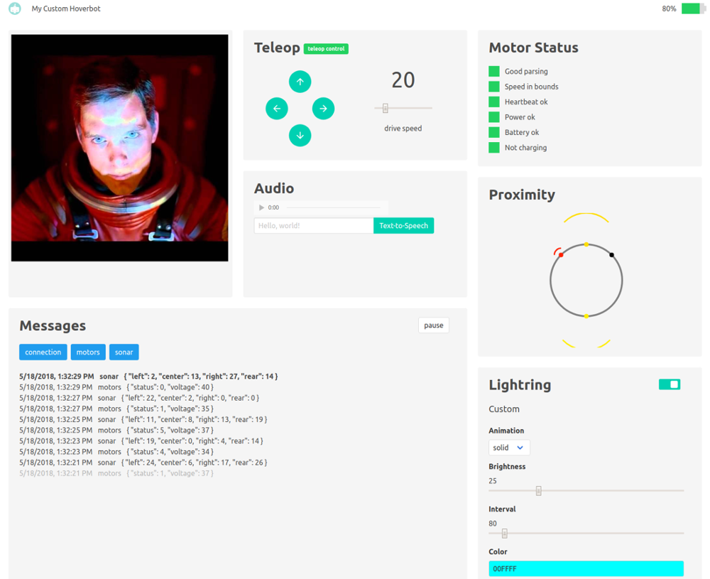
The Hoverbot software is a Node.js application. The default code enables control of the robot via a teleoperation interface, shown below. The interface includes a live camera stream, a "live" audio stream, a directional control pad, a text-to-speech input box, LED strip controls, a sonar sensor visualization, a health status for the hoverboard motors, and a message log. The interface is a useful debugging tool and a starting point for building more interesting applications.
Why javascript?
Most robots are effectively just collections of connected sensors and actuators that broadcast data and listen for particular events to take action on, which makes the event-driven architecture of Node.js a great framework for Hoverbot. Node.js' package manager, npm, is another reason to use JavaScript due to its engaged community and large ecosystem of open source libraries. Hoverbot leverages several npm packages, including serialport and pi-spi.
Extensible
The Hoverbot code is written to be extensible. All data producers emit named events to which you can easily add custom listeners. Take a look at the event listeners in customHoverbot.js as an example.
You can easily extend the current sonar data listener to do more than just broadcast data. Presuming you're interested in taking the squishy human out of the loop, turning this teleoperation application into something autonomous, you could add some logic to let the robot drive on its own, using the sonar data to avoid obstacles. It might look something like this:
// This is a naive implementation for demonstration purposes!
// BE CAREFUL, THE HOVERBOT MAY NOW WANDER AS SOON AS IT BOOTS!

// Listen for spi to emit sonar data, relay data via broadcast for the server to send to the client
hoverbot.spi.on('sonar', (data) => {
  if (data.center > 5) { // Nothing in front? go forward
    hoverbot.motors.move(-20, -20);
  } else if (data.left > 5){ // Side clear? turn that way
    hoverbot.motors.move(-20, 0);
  } else if (data.right > 5){ // Other side clear? turn that way
    hoverbot.motors.move(-20, 0);
  } else if (data.rear > 5){ // Only rear clear? back up
    hoverbot.motors.move(20, 20);
  } else { // No direction clear at all? STOP!
    hoverbot.motors.move(0, 0);
  }
});
Be sure to read the documentation in the github repo for more detail, and feel free to submit a pull request when you're done creating something awesome!
Hoverbot is easy to assemble using basic hand tools and repurposed consumer hardware. This blog post details one possible way to assemble Hoverbot, but it can be built using whatever materials you have handy, as long as you have the necessary core components (a hoverboard and a Raspberry Pi).
Physical assembly
Disassemble the hoverboard
Save the motor controller, motors, motor mount plates, power switch, charge port, and battery.
Case removal
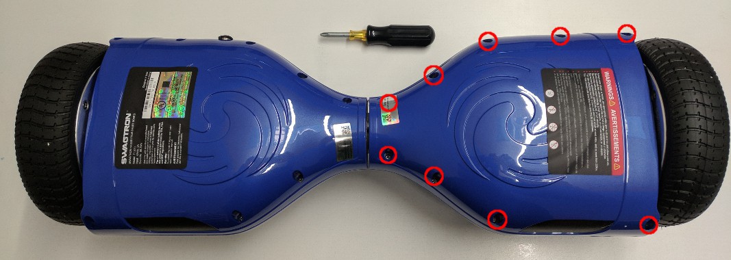
From the bottom of the hoverboard, remove the 9 Philips head screws from the side without the power button/charge connector. In order to remove the plastic case, you'll have to disconnect the LED cable from the gyro board. Set aside the plastic case.
Battery disconnect
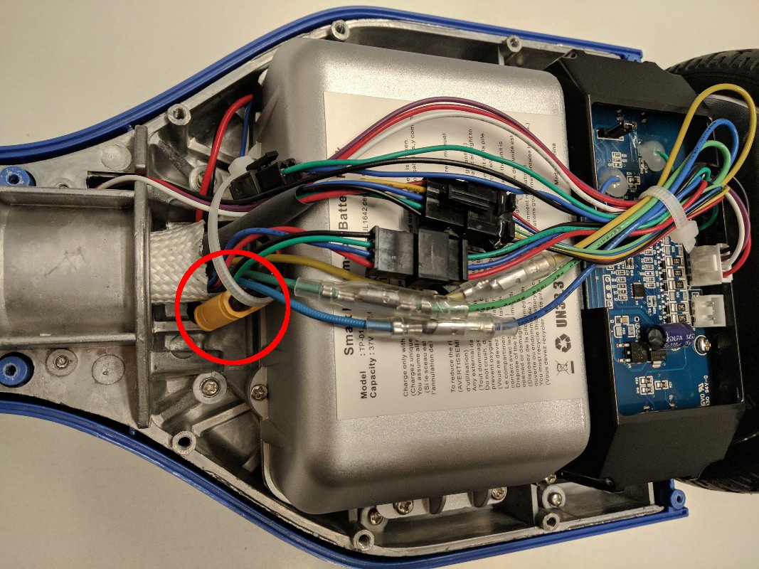
Disconnect the yellow battery connector circled in red below. You can remove the zip tie holding the cable bundle together.
Motor controller removal
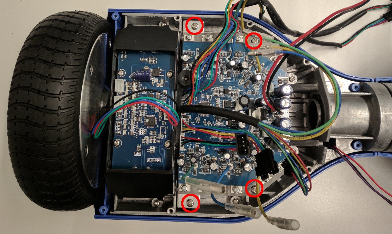
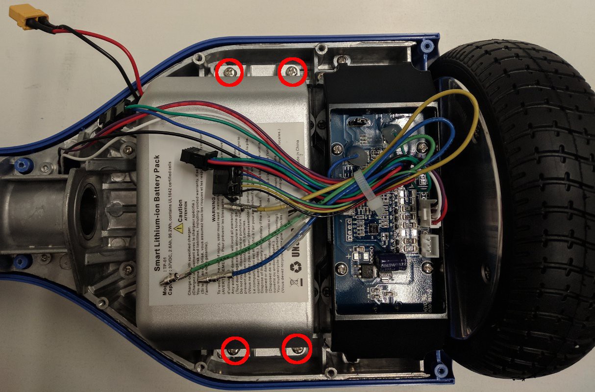
Remove the 9 Philips head screws holding the other half of the bottom case and disconnect the power button, charge connector, and LED panel. Disconnect all connectors on the motor controller - including the connectors on the opposite side - and fish the cables through the center tube. Then remove the 4 Philips head screws - circled in red in the image below - that hold the motor controller and heat sink to the hoverboard body. This might be a good time to program the new firmware on the motor controller as it is easy to test that it is working when the wheels are still connected to the hoverboard body.
Battery removal
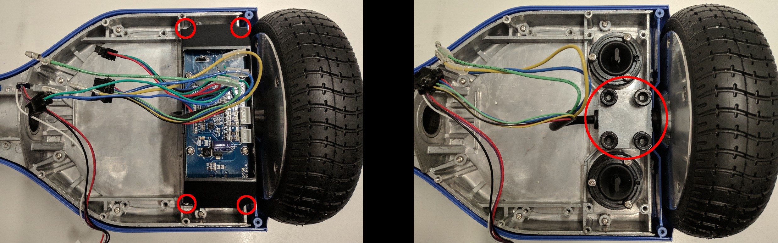
Remove the 4 Philips head screws holding the battery to the hoverboard body. You can cut the zip tie bundling the cables and may need to remove a secondary battery connector as well. If your battery is not in a hard case as shown below, it will likely be held down by double-sided adhesive tape underneath. If this is the case, you'll need to very carefully pry it off the hoverboard body. WARNING: DO NOT USE SHARP OR HARD IMPLEMENTS TO PRY ON THE BATTERY. DO NOT PUNCTURE THE BATTERY.
Wheel removal
Remove the 4 Philips head screws holding the gyro board mounts on both sides of the hoverboard and set the gyro boards aside. Then remove the 6mm Allen head screws holding the wheels to the hoverboard body. Be sure to save the square metal mounting plates for the wheels.
Switch removal
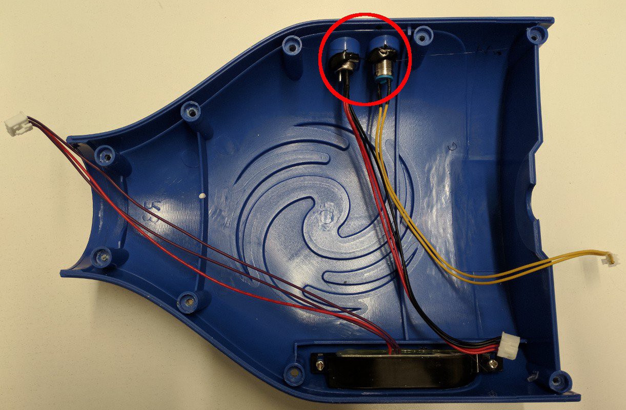
Remove the power switch and charge connector from the case half. You may need to remove some glue that is on the retaining nuts. Make sure to save the retaining nuts.
Gathered parts
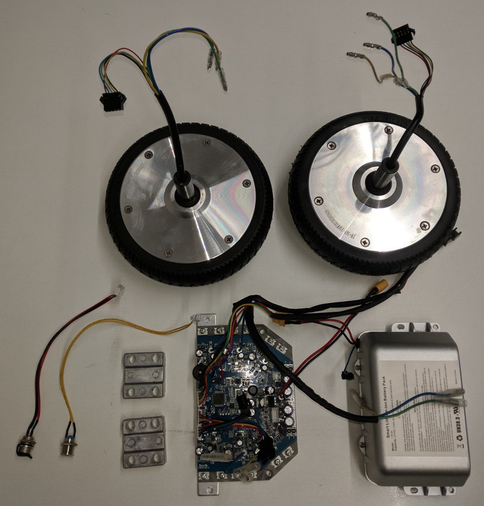
Now that you've disassembled the hoverboard, you should be left with the collection of parts below.
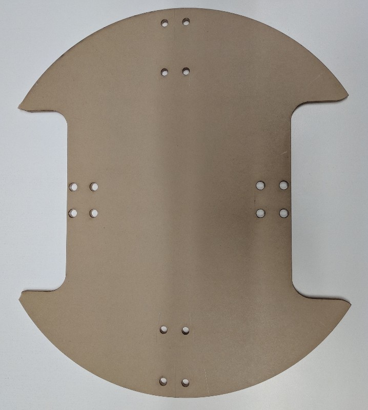
Build a base support
The base of the IKEA table isn't quite strong enough to support heavy loads after it's been cut to make room for the wheels, so you'll need to make a support for it. Print out the base support template pdf and use a drill and a jigsaw to cut a support from thin plywood. Alternatively, you can laser cut a base support from 0.25" acrylic (base support template dxf).
Mark where to cut the base
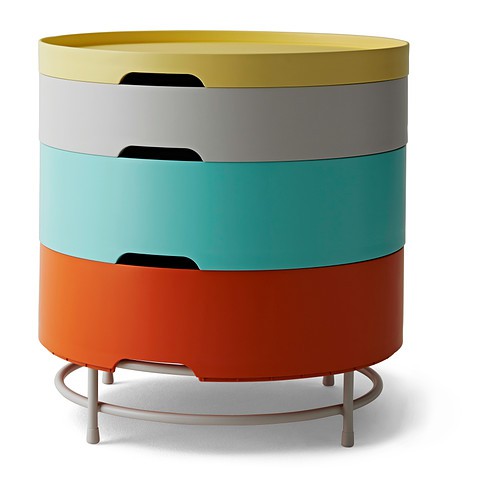
When referring to the IKEA table sections the orange or teal sections in the image below will be the "tallest" sections, the gray will be the "medium", and the yellow will be the "thinnest".
To mount the wheels and casters, you're going to cut some holes in this lovely piece of quality Swedish furniture. Use the base support itself (or the template you printed out) and a sharpie to mark the cuts on the bottom of the tallest section.
Actually cut the marked holes
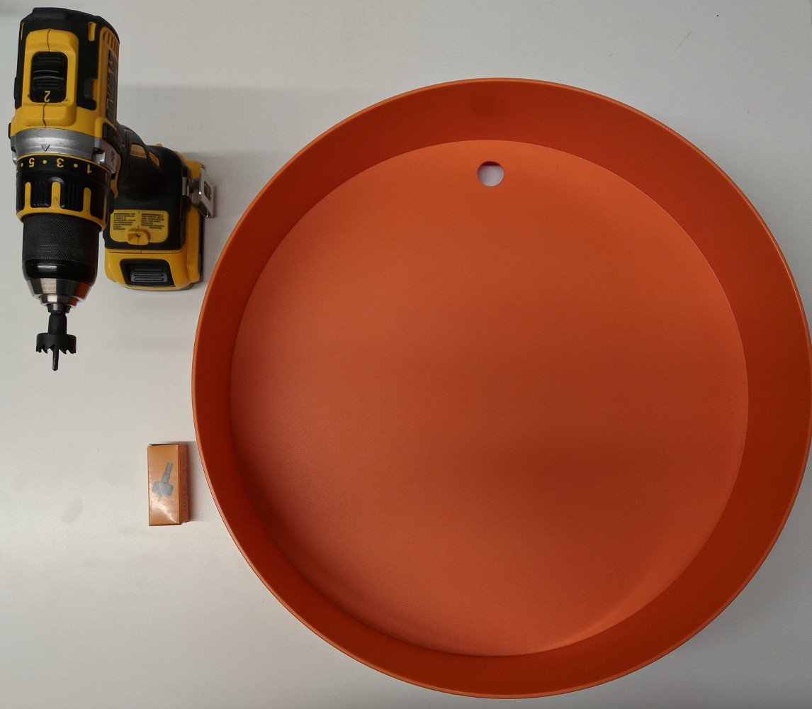
Using a Dremel with a cutoff wheel, cut out the wheel holes you just marked. Use a drill to cut the bolt holes for the casters. Please wear safety glasses - or better yet a face shield! - while preforming this step. Spinny things are dangerous!
Drill holes in the side wall
Drill the holes in the side walls of the tallest section for mounting the sonar sensors (use the hole saw provided with the automotive backup sensor kit). Note that the wheels have already been installed in the image below, but it is recommended that you drill the holes before installing anything.
Drill holes on the side walls of the tallest section for mounting the power switches and the charge connector.
Mount motors
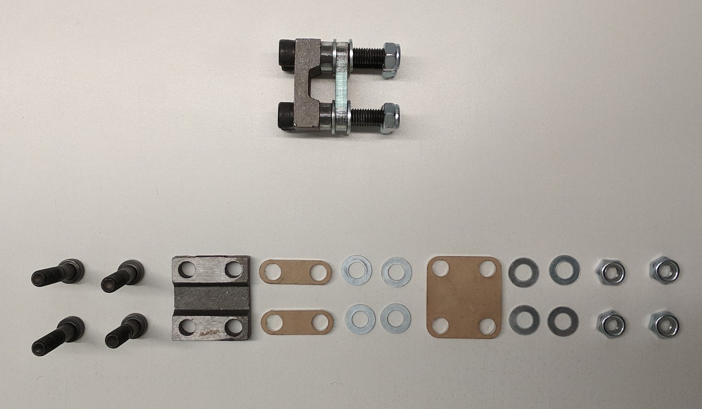
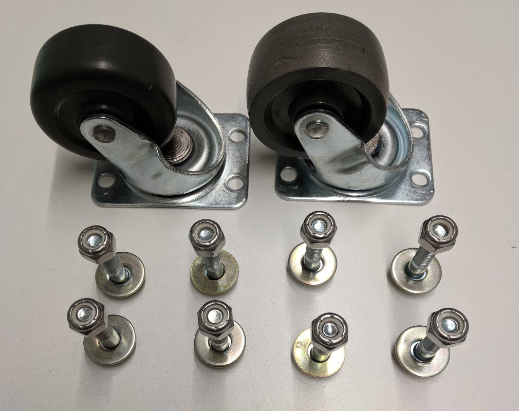
To mount the wheels, you'll need the following hardware:
8: Bolts (M8x35)
2: Mount plates (from hoverboard)
4: Side spacers 0.30" (can be laser cut or just stacked washers) TODO add dxf for laser cut spacer
2: Bottom spacers ~0.25" (can be laser cut or just stacked washers) TODO add dxf for laser cut spacer
16: M8 washers
8: M8 nuts (nyloc preferred)
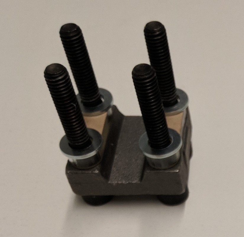
Assemble 4 bolts, a mount plate, and 2 side spacers. (In this case, an acrylic piece was used with 1 additional washer per bolt).
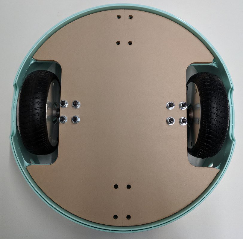
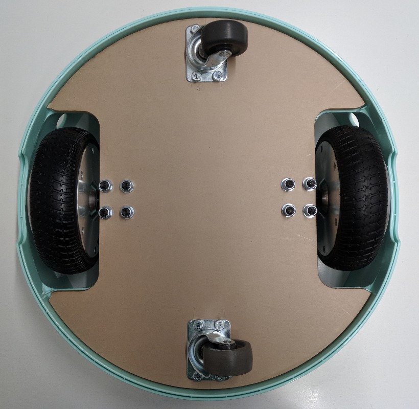
Slide the bottom spacer between the mount plate and the IKEA table section such that the holes line up. Then place the flat of the motor shaft on the flat of the mount plate and bolt in place.
Tighten the bolts and repeat for the other side.
Mount the casters
You'll need:
8 bolts (M6x30 or 1/4")
8 washers
8 nyloc nuts
2 casters
Mount the casters. The washers should go under the nuts on the top side of the robot.
Drill cable pass though hole
Drill a hole in the bottom of the medium IKEA table section using the hole saw.
Electrical assembly
Master power switch
In this assembly, all of the systems will be powered by the hoverboard battery for ease of charging and setup. As a safety feature you can add a physical power switch between the battery and everything else. Fortunately, the hoverboard battery uses a common remote control hobby connector (XT60) for which you can find an off the shelf switch.
12V system
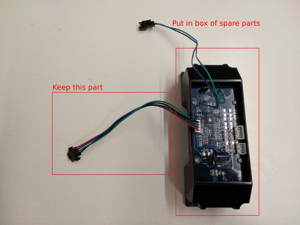
The hoverboard motor controller has a 12V supply that can be used to power the sonar box. This 12V supply is most easily connected by using the wire that previously powered the hoverboard gyro boards. As you won't be using the gyro boards, you can cut the wire and connector (marked below) from the gyro boards and solder the backup sensor power wires to the cut off cable.
5V system
The hoverboard motor controller also has a 5V supply that is used to power the hall effect sensors. Unfortunately that supply does not provide enough current for either the Raspberry Pi or the LED strip, so you'll have to find another 5V power source.
To provide a higher current 5V source, an automotive USB charger can be repurposed to draw power from the hoverboard motor controller 12V supply. The USB port is quite convenient for the Raspberry Pi as it is powered via a USB connection :) It is less convenient for the LED strip because you'll need to solder the LED power wires to the 5V output of the automotive USB charger. Alternatively you can cut open a USB cable and solder to the LED power and ground lines. Be sure it is a USB cable with thicker conductors - power-only USB cables are usually good for this.
(TODO add pictures of this)
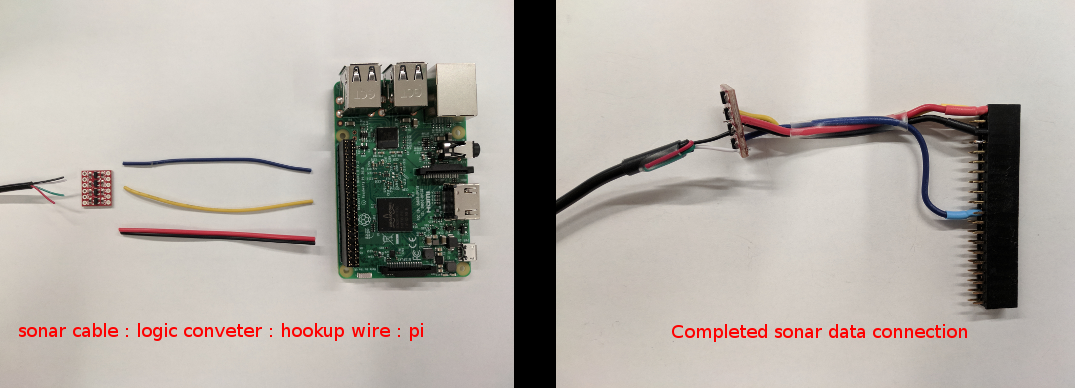
Sonar data connetion
The sonar data is output at a 5V logic level and the Raspberry Pi is only tolerant of 3.3V on the input pins. You can either use a pair of resistors as a voltage divider or use a logic level converter to step down the 5V to 3.3V. The stepped down signal should be connected to the MISO pin of the Raspberry Pi which is pin 21 on the Raspberry Pi GPIO header. The sonar display wires should be connected as you determined them in the project log on reverse engineering automotive backup sensors. Do not trust the sonar display wire color as it may not be the same as shown here. Note the two unused (5V and Buzzer) sonar display wires are folded over and heatshrinked (heatshrunk?) to protect from shorts.
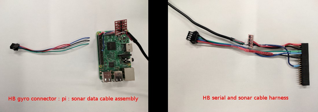
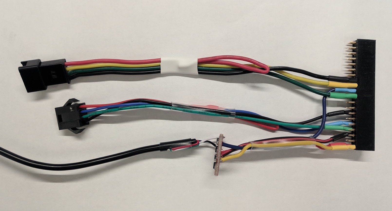
Hoverboard serial connection
The hoverboard motor controller uses 3.3V serial, which is a perfect match for the Pi. Using the second gyro board connector, attach the blue cable to the Pi serial Rx (pin 10) and the green cable to the Pi serial Tx (pin 8). With the flat edge of the motor controller facing away from you, this gyro connector should plug into the leftmost connector. It is worth double checking that the wire order on the leftmost gyro connector is - from outboard to inboard / left to right - Black, Green, Blue, Red. Note that the red power wire on the gyro connector is folded over and heatshrinked to keep it from shorting on anything.
LED data connection
The LED strip data lines are setup to take a 5V signal but they can be connected directly to the Pi, as the 3.3V signal the Pi outputs should be enough to drive them. The DIN (data in) line on the LED strip should connect to the Pi MOSI output which is pin 19. The CIN (clock in) line on the LED strip should connect to the Pi SCLK output which is pin 21. If you have trouble with the lights and you are using a logic level converter for the sonar input, you can use the same converter to step up the Pi's 3.3V signal to 5V.
If you buy a full meter of LED strip it should come with connectors on both ends. You can cut off the output end (the one the arrows on the LED strip point to) and use it to connect to your Pi headers. Note that the red power wire is again heatshrinked to prevent it from shorting (power is supplied to the LED from the 5V connection as noted above).
Hoverboard power and charge
The power switch and charge connector for the hoverboard motor controller will connect as they were in the hoverboard. If you drilled holes for these in the side of your IKEA table, be sure to feed the connectors though from the outside before plugging them in.
Sonar sensor connections
Connect the sonar sensors to the sonar sensor hub in this order:
Left sensor: port A
Center sensor: port B
Right sensor: port C
Rear sensor: port D
Be sure to feed the cables though the holes in the side of the IKEA table before plugging them in to the sonar sensor hub.
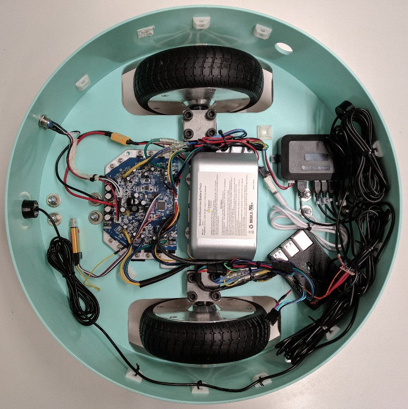
Electronics placement
Using double-sided tape (or sticky Velcro) and zip ties, mount all of your components to the bottom of the tallest IKEA table section.
Not shown above: web camera, LED strip, speaker
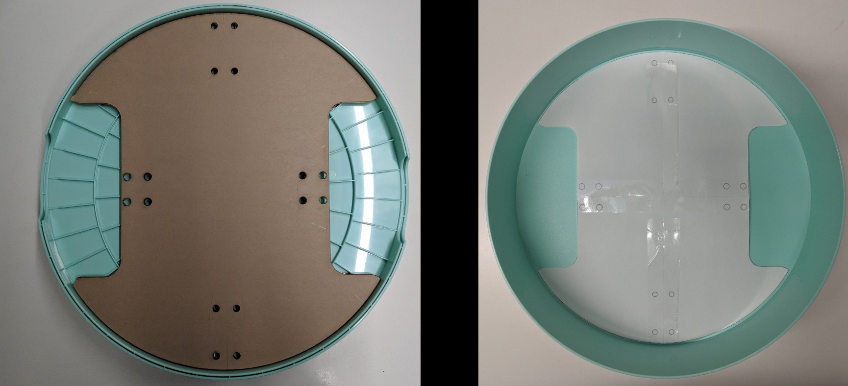
LED strip and diffuser installation
Place your plastic diffuser inside the medium IKEA table section. Be sure the diffuser is not pushed all the way to the edge such that you can snuggly place the thinnest section on top of it. You can use hot glue to hold it in place. Snake the LED strip cables though the hole in the base of the medium IKEA table section and connect them to the harness you built for the Pi.
TODO add pictures for LED and LED diffuser installation
Web camera installation
The web camera connects directly to the Pi via USB. The cable can be snaked though the hole that the LED connectors are using in the base of the medium IKEA table section. You can then either use the hole saw to add a hole to the thinnest IKEA table section or route the cable out the handle. Given the variety of web cameras, a mounting solution will not be covered here. It is likely easiest to attach it to the thinnest IKEA table section using double-sided tape.
Speaker installation
The speaker can be pretty much any off the shelf battery powered speaker with a 3.5mm line-in headphone plug. The location of the speaker is not particularly critical as long as you can hear it. Double-sided tape is perfectly acceptable for mounting. The line-in plug of the speaker will connect to the headphone jack on the Pi
Celebrate! You've just assembled a hoverbot! YAY! Everybody dance!!!
Aftermarket automotive backup sensors are cheap and ubiquitous. They use transducers to produce an inaudible ping and receive the reflected response - the time it takes for the ping to return indicates how far away any potential obstacles may be, which is shown on some kind of dash-mounted display. These transducers are very similar to those found in the maxbotix ultrasonic proximity sensor but are significantly cheaper. So what's the difference? The automotive kits don't include the fancy USB interface to programmatically read the data. However, with a little bit of tinkering you can intercept the data signal connected to the dash display and read the data just the same.
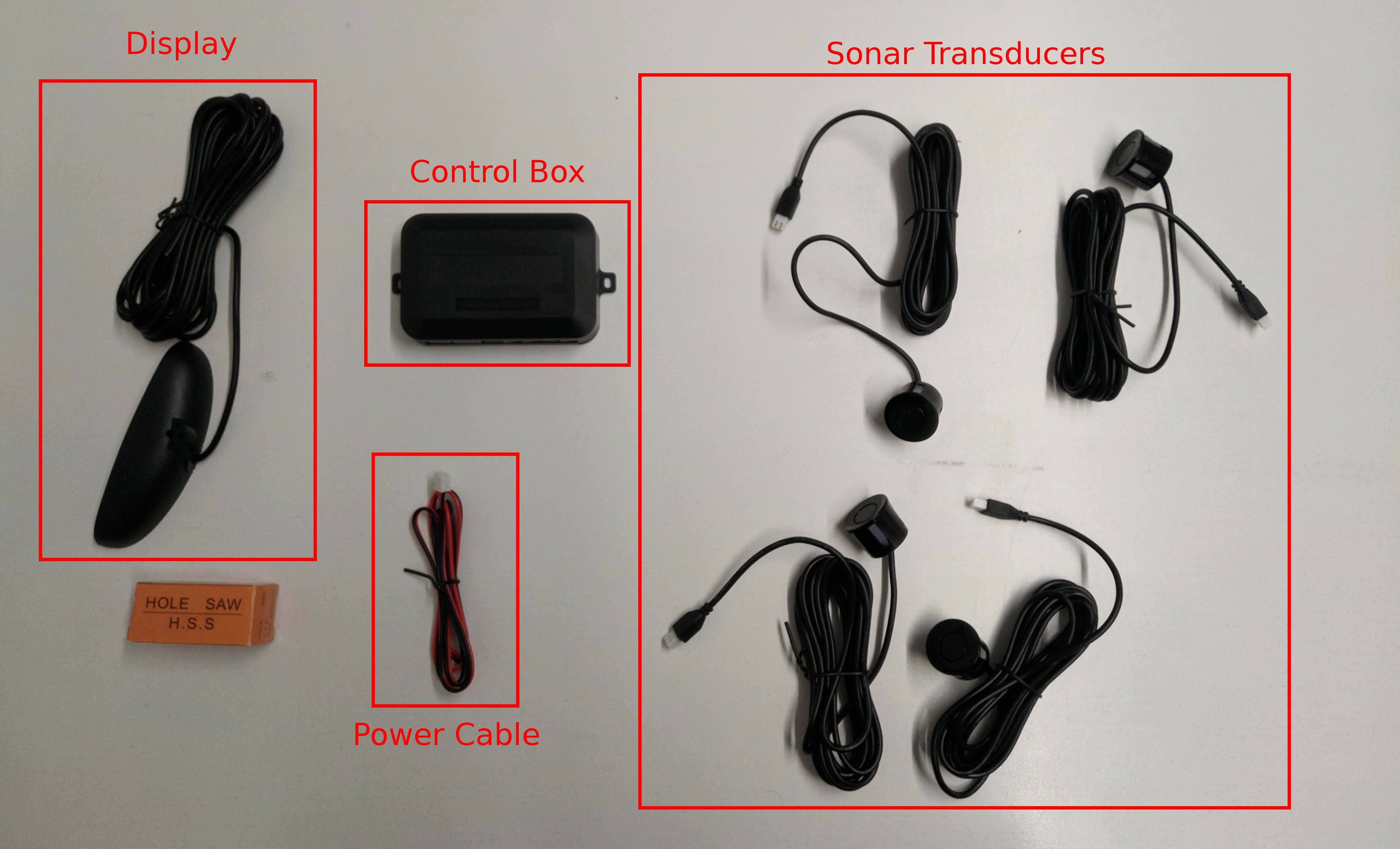
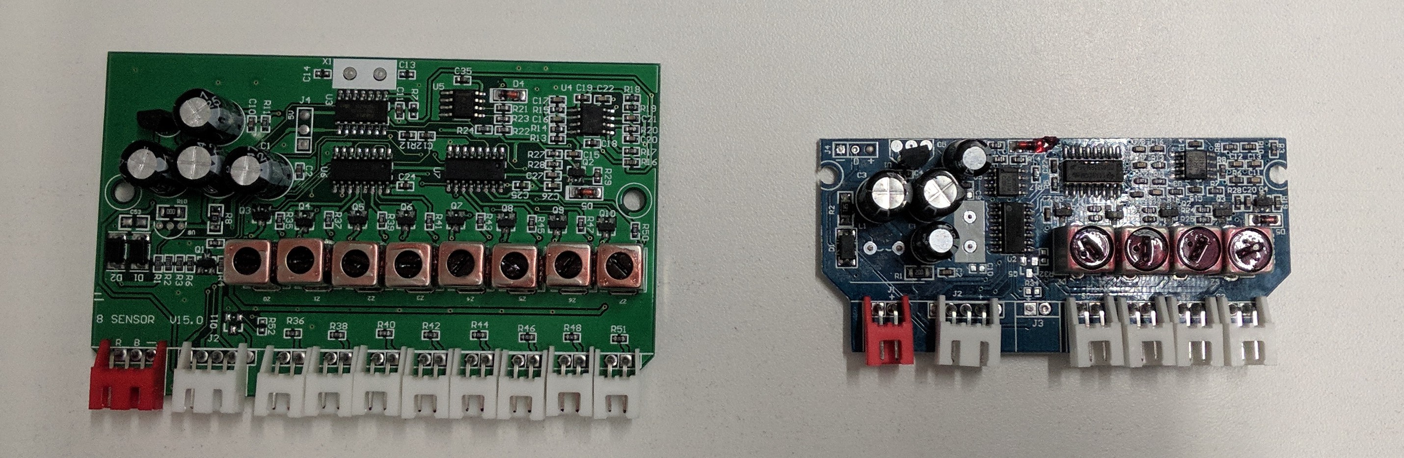
Automotive backup sensor kit
The kit
Most backup sensor kits include 4 transducers, a control box, a power cable, a display, and a hole saw. The control box generates the pings for the transducers, listens for the ping response time from the transducers, interprets the response times as distances, and finally aggregates those distances to send to the display.
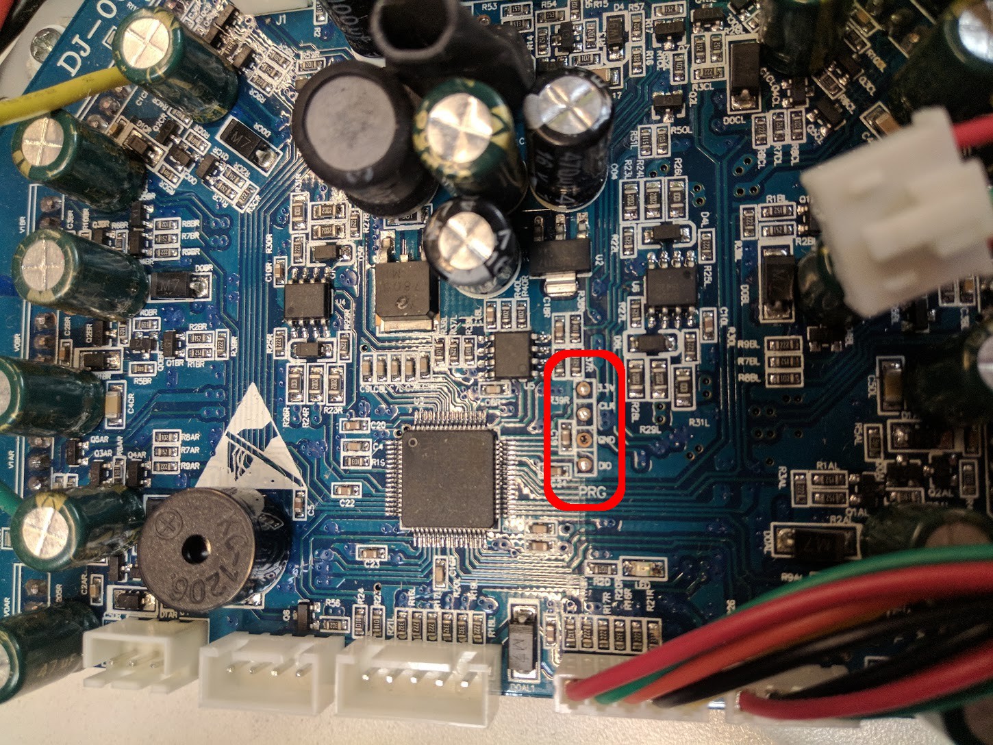
Show me the data!
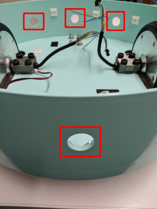
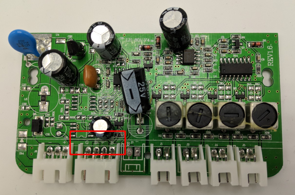
You can intercept the aggregated distance data by connecting a microcontroller to the display cable, but you'll first need to identify the data pin by taking a look inside the control box. Open the control box by removing the 2 screws in the bottom of the case. If you are lucky, the silkscreen on the board will include a label for each pin as shown in the red box in the image below. G is for ground, D is for data, + is for display power. You might also see a B for buzzer, but not all kits have it.
If you're not so lucky, your board may be completely blank. That's a bummer, but it's not a blocker and you can still figure it out. First, connect the power cable to the control box and a 12v supply. Make sure nothing but the power supply is plugged into the control box. Carefully use a multimeter to check for voltage between ground and each of the display cable pins. If your board has 3 pins one of them should have no voltage - this is ground. Another pin should have 5v - this is the display power. Finally, one should have a low, fluctuating voltage - that's the data pin. If your board has 4 display pins, there will also be a second pin with no voltage, one of which is the buzzer and the other is ground. Change your mulitmeter to measure resistance and compare the two 0 voltage pins with ground. The one with no connection (infinite resistance) to ground is the buzzer. At this point you might want to label the pins so you don't have to do it again.
Understanding the data
If you just want to get the data and move on, you can skip ahead to the next section. If you're compulsively curious about how things work, read on.
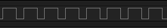
Using a Saleae logic analyzer connected between the data pin and ground, you can observe the signals between the control box and the display. You might notice that the board's data line is nominally low and the width of the high pulses changes as you move things around in front of the sensors.
After sufficient arm waving and some strange looks from people in your vicinity, you might start to notice a pattern; there is a consistent 2 ms high pulse followed by a 0.01 ms high pulse, which is then followed by 32 more high pulses of either 0.01 ms or 0.02 ms. At this point you might take a wild guess that a 0.01 ms high pulse represents a 0 and a 0.02 ms high pulse represents a 1.
The 2 ms high pulse followed by the 0.01 ms high pulse is a header flag that indicates the beginning of data. The following 32 pulses represent the data itself - 8 bits for each of the 4 sensors. By observing how the data changes in response to motion in front of the sensors, you can determine which 8 bits correspond to which sensor.
An example trace from the data pin is shown below.
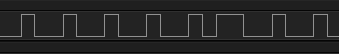
Note that while each sensor connection has a physical label on the control box A, B, C or D, the order of the sensors in the display data signal is not alphabetically ordered relative to those labels, as highlighted in red below.
By comparing some physical measurements to the observed data signal, you can determine that the integer data is ~10cm per unit, so a reading of 4 would indicate an object ~40cm away from the sonar. A value of 255 indicates that no obstacle is detected because the sensor did not receive a reflected response from the ping. Note that the maximum range of these sensors appeared to be around 150 cm. Anything further away returned a value of 255. The following table shows an example of how to map the trace shown above to distance measurements.
Sensor A
Sensor D
Sensor C
Sensor B
11111111
00000100
11111111
11111111
255
4
255
255
N/A
40 cm
N/A
N/A
Reading the data
Now that you understand the data format, you can interface with the control box. However, because the data is transmitted in a non-standard format (no, variable pulse width binary is not standard!), you have to write some custom code.
GPIO polling/interrupts
One option for reading the signal is via a GPIO pin on a microcontroller such as an Arduino or an ESP. Using either polling or interrupts to detect a pulse, you can then use a timer to measure the width of each pulse. When the header flag pulses are detected, you can fill a buffer with the following 32 pulse widths. The Sonar RE github project includes code examples for both the polling-based and interrupt-based solutions on an ESP32 thing.
The disadvantages of polling and interrupt based methods include strict timing requirements of your code and heavy processor use, respectively. To get around these problems you can use built in methods of reading data signals, such as SPI.
SPI
Instead of using polling or interrupts to check for the pulses, you can use a device that has SPI support by connecting the display data pin to the SPI MISO pin. The SPI communication interface uses low level systems to deal with timing and recording of data pulses so you don't have to do it yourself in the code with polling or interrupts. However, because the display data is not a proper SPI interface, you will have to adjust the SPI data rate and do some additional parsing of the result.
You will have your system read a number of bytes from the MISO pin and to do so it will toggle the SPI clock pin (which you wont connect to anything) and at each toggle it will read the state of MISO pin and return the values it reads as bytes. By setting the SPI data rate to be above the nyquist rate of the display data signal you will be sure to receive every high pulse as a series of 1's in the returned bytes.
You'll need to read enough bytes over SPI to ensure you get the header and all 32 data bits. The read in bytes can then be parsed to find the header and the data bits. An example implementation can be found in the Sonar RE github project (Implemented on a Raspberry Pi).
Differences between backup sensor kits
Data formats
Two different data formats were found across a variety of kits during testing and one has significantly more useful data than the other. The kits with control boxes that have different data formats are packaged in the same exact physical cases, so another way to determine which kit is which will be necessary (likely the display that comes with the board will be the way to check). TODO(link to a good kit or a way to easily differentiate)
One control box outputs 2 bits of depth information for each sensor and then 8 bits of resolution for whichever one of the sensors is closer. This is not great as 2 bits of depth data works out to only ~0.3 meter resolution, which isn't really enough...
The other control box outputs 8 bits of depth data for each sensor, as is described in detail above.
Number of sensors
There are 8 and 4 sensor kits, and it appears the 8 sensor version is just doubled up circuitry of the 4 sensor version, which is then connected to a mux and switched via a 12v input to the board. This is because it is meant to have 4 sensors on the back of the car and 4 on the front. 12v switching is a little harder than 5v and the 8 sensor kits seem to use the data format with very poor distance resolution so they are not recommended.
There are plenty of cheap small robots available and there are plenty of expensive large robots available, but it is hard to find cheap robots that can move a reasonable amount of weight. And what good is a robot if it can't move anything around? Hoverboards, as it turns out, include a convenient collection of components that can be used to power and drive a cheap, capable robot.
High torque, direct drive, brushless motors (with large diameter wheels)
Motor controller
High capacity battery
Battery charger
Great! Lets make a hoverboard robot
The hoverboard motor controller is programmed for a human controlled, self-balancing system. This system consists of two gyroscope sensors feeding data to the motor controller, which responds by moving the motors to keep the gyros "flat". This is what keeps the human upright most of the time.
But we want to replace the squishy human with a cold unfeeling robot. Some people have already shown how to remove the human from the hoverboard control loop by sending fake gyro data. These examples include Low cost two wheels drive - hoverboard hack and How I hacked the Self Balancing Scooter. Unfortunately the original firmware is written such that it will increase the speed of the wheels if it is fed a constant gyro angle. This behavior makes it challenging to move the motors at a constant speed.
Well, what now then?
Fortunately most hoverboard motor controllers use a common micro-controller (STM32F103 or a clone) that can be reprogrammed. We can write new firmware to use a custom communication protocol to drive the motors in a way that is betted suited for robotics applications.
Check your hoverboard motor controller for compatibility with available firmware
There are at least two different motor controllers in common use by hoverboard manufacturers; one with a single motor controller that drives both wheels and another with a controller for each wheel and a data connection between them. This project currently includes custom firmware compatible with the single board controller. See this google doc for further instructions on identifying different hoverboard motor controllers.
Remove the motor controller and attach programming header pins
Before you can reprogram the motor controller you'll need to first remove it from the hoverboard (for detailed instructions see the physical assembly blog post). You'll also need to remove the motor controller board from the aluminum heat sink plate - it is attached via the remaining screws through the transistors.
Once the motor controller is removed, you'll need to solder the programming header pins to the board - don't worry, it's not very hard. Some motor controllers have the programming header pin holes filled with solder (as shown in the picture above). If they are filled you will need to clean them out using either a solder sucker or solder-wick. Once the holes are clean, solder four regular 0.1" spacing header pins to the board.
(Though not strictly necessary, you can breakout the STM32F103's reset pin for more reliable programming. You can still reprogram the board without this step, but it may require more retries.)
After soldering on the programming header pins, reattach the motor controller to the aluminum heat sink plate.
Flash the new firmware
Connect an ST-link V2 to your freshly soldered header pins (and the reset pin if you added it). The hoverboard motor controller does not need to be - and probably should not be - connected to anything besides the ST-link while you are flashing it. Follow these instructions to download and update the firmware.
Does it work?
You left the upper cover of the hoverboard attached and the motors still bolted to the frame, right? Place the newly flashed motor controller back where you removed it from and reconnect everything except the wires going to the gyro boards. Then connect your serial device of choice* to the TX, RX, and GND pins of the leftmost gyro connector, which is likely the connector with the longer cables). Power on the hoverboard and send a command to the motors. The firmware documentation includes an example of the control instruction format.
* Make sure it is 3.3v serial as 5v serial will permanently damage your hoverboard motor controller
 Isabelle Simova