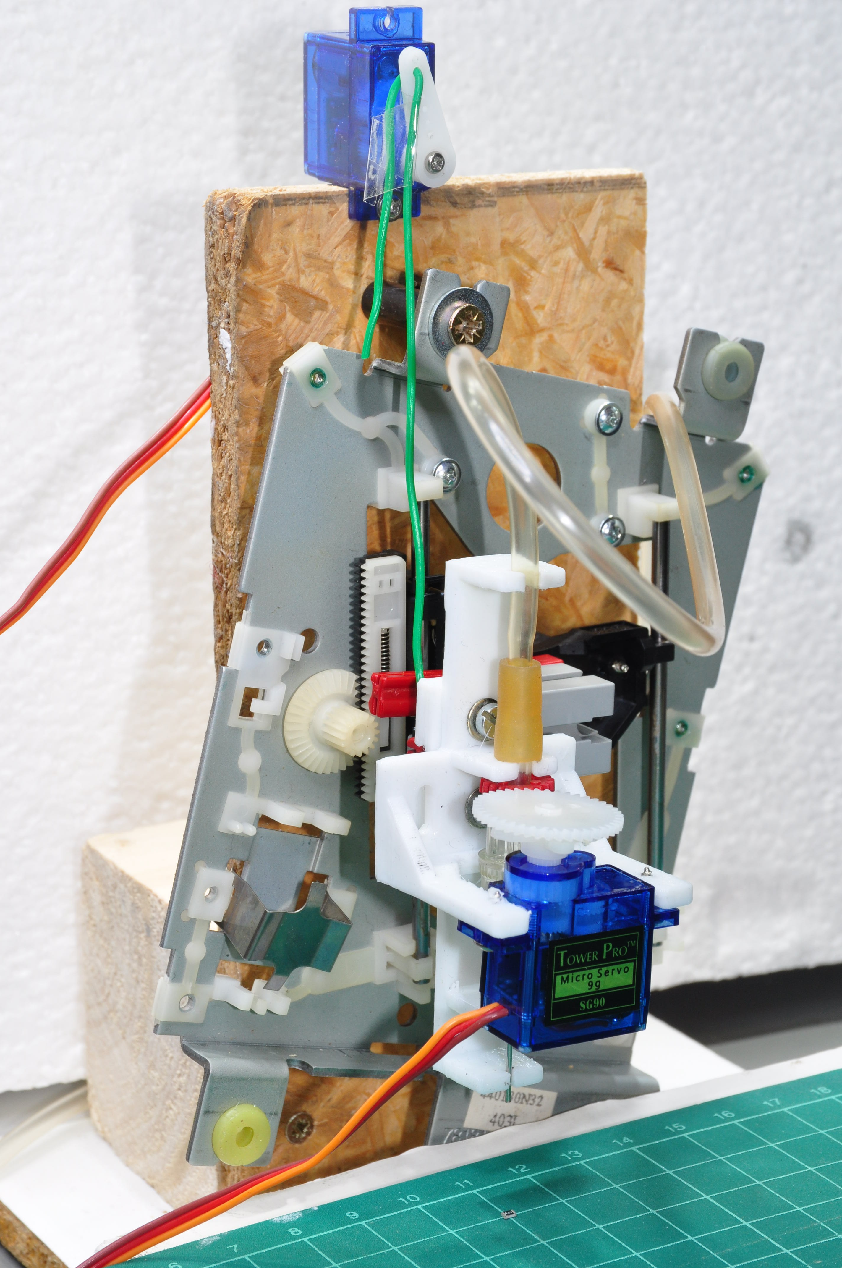
I am using an old CD drive for the z axis of my simple test rig. Originally, the sled is driven by a motor (a DC motor, most other drives use stepper motors). But I don't really want to actively drive the sled downward as this only smashes even harder on the poor little SMT part when it hits the PCB. I had issues with cracked resistors on manufactured boards and I would like to avoid that problem.
I tried driving this motor very gently by using the smallest PWM rate I could still get away with - but it still accelerates too much and hits the ground so hard that the part often just jumps away and gets lost on the floor.
A stepper drive would avoid building up an excessive speed, but I still don't have any proper height information and can't tell when I have to stop trying to drive the needle further down.
This is why most other builds use gravity for the downward movements and connect the z sled only loosely to the motor. So do I now: A second servo lifts the z sled by pulling on a string and downward movement happens by gravity only while the speed is still controlled by the servo.

Et voilà: The parts stay put and can easily be picked up and released by the needle! Have a look (rotation is still controlled manually using a simple servo tester, so don't expect exact 90° movements):
That was easier than expected. So what's the next step? I would love to build a full pick-and-place machine. But that would be a separate project.
To keep things interesting I would opt for a DC motor drive from old inkjet printers for the X and Y axis. These drives allow for closed loop operation and they are remarkably fast and precise.
 Michael Mayer
Discussions
Become a Hackaday.io Member
Create an account to leave a comment. Already have an account? Log In.