 ptrav
ptrav-
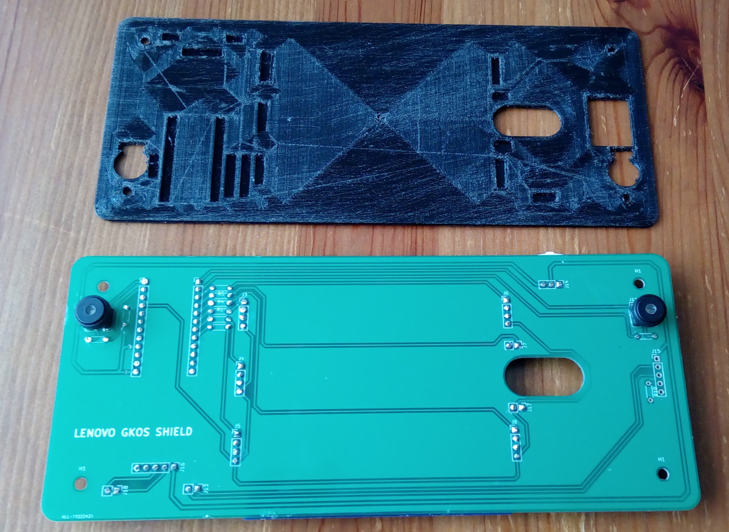
Completed PCB Assembly
12/23/2018 at 07:23 • 0 commentsAfter a long while (my 3D printer waited on parts), resumed the project.
The assembled PCB is out of the storage box:
![]()
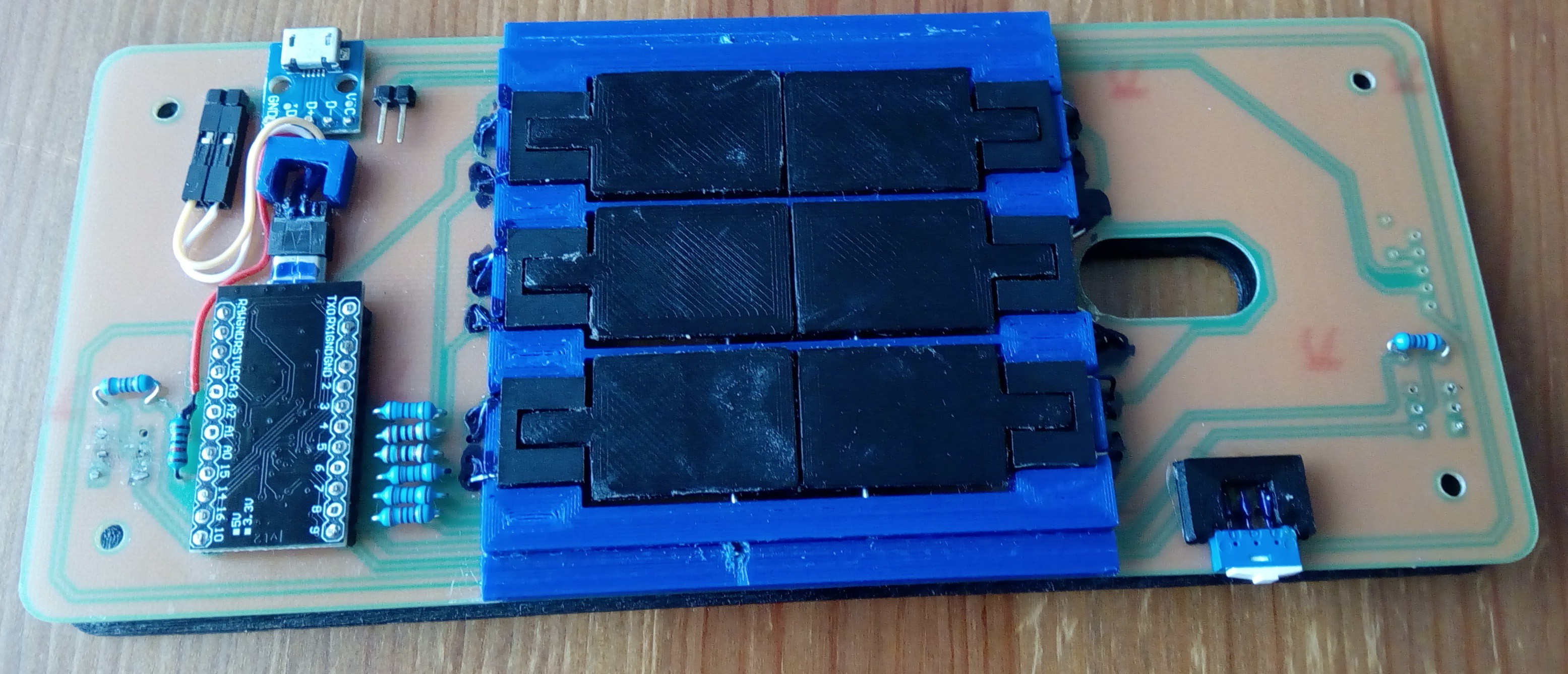
Note 6 optical buttons in the middle:
![]()
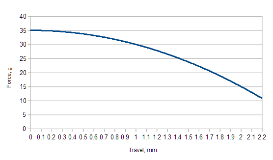
The buttons have inverted force profile: the initial force is 35 gram, then decreases down to 11 gf hold force. The full key travel is 2.2 mm, and the button press is registered at 1.2-1.3 mm. Buttons work with a pleasant metal click; at this point no intention to make it quiet (let people admire a mechanical keyboard on the smartphone!)
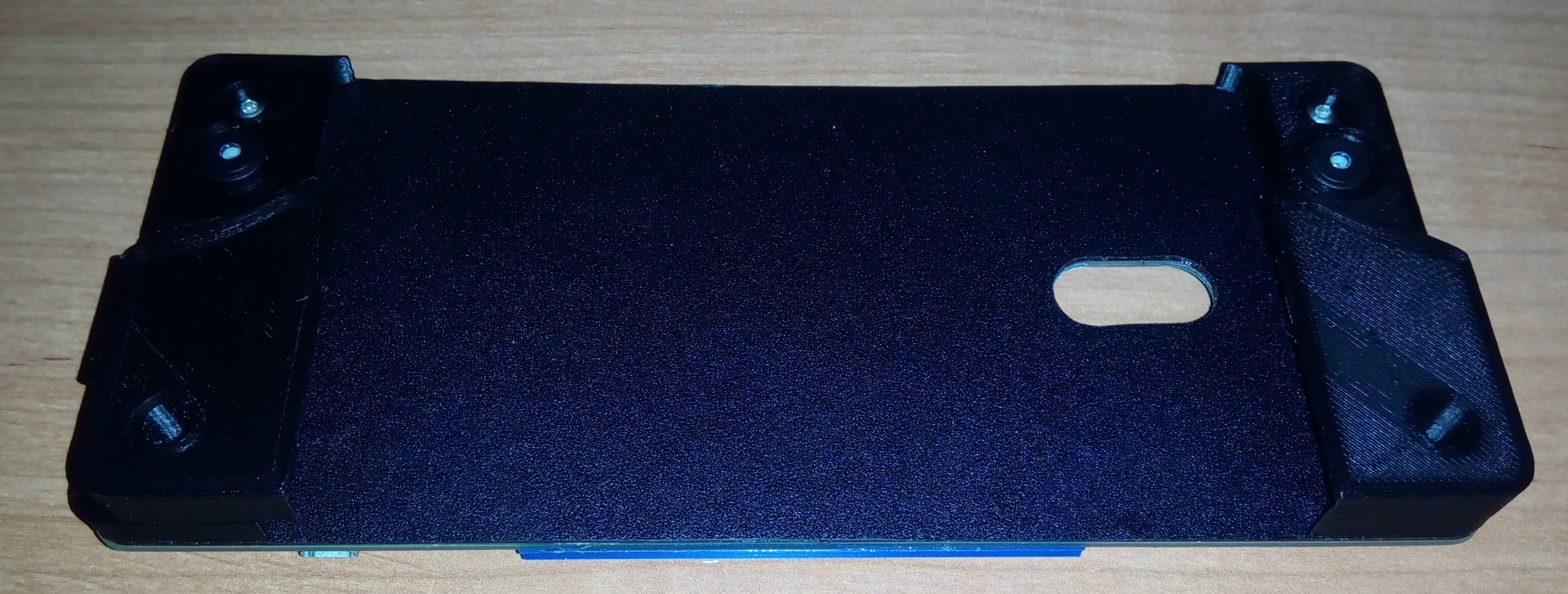
The keyboard top now looks like this:![]()
Note the left handle having a spring-loaded latch, which allows the phone insertion and removal. The handle files STL is uploaded. -
Started PCB assembly
08/22/2018 at 05:35 • 0 commentsMy PCBs from Allpcb.com and the components have arrived a while ago, but I had to delay the assembly due to some unrelated stuff.
Finally the assembly have started.
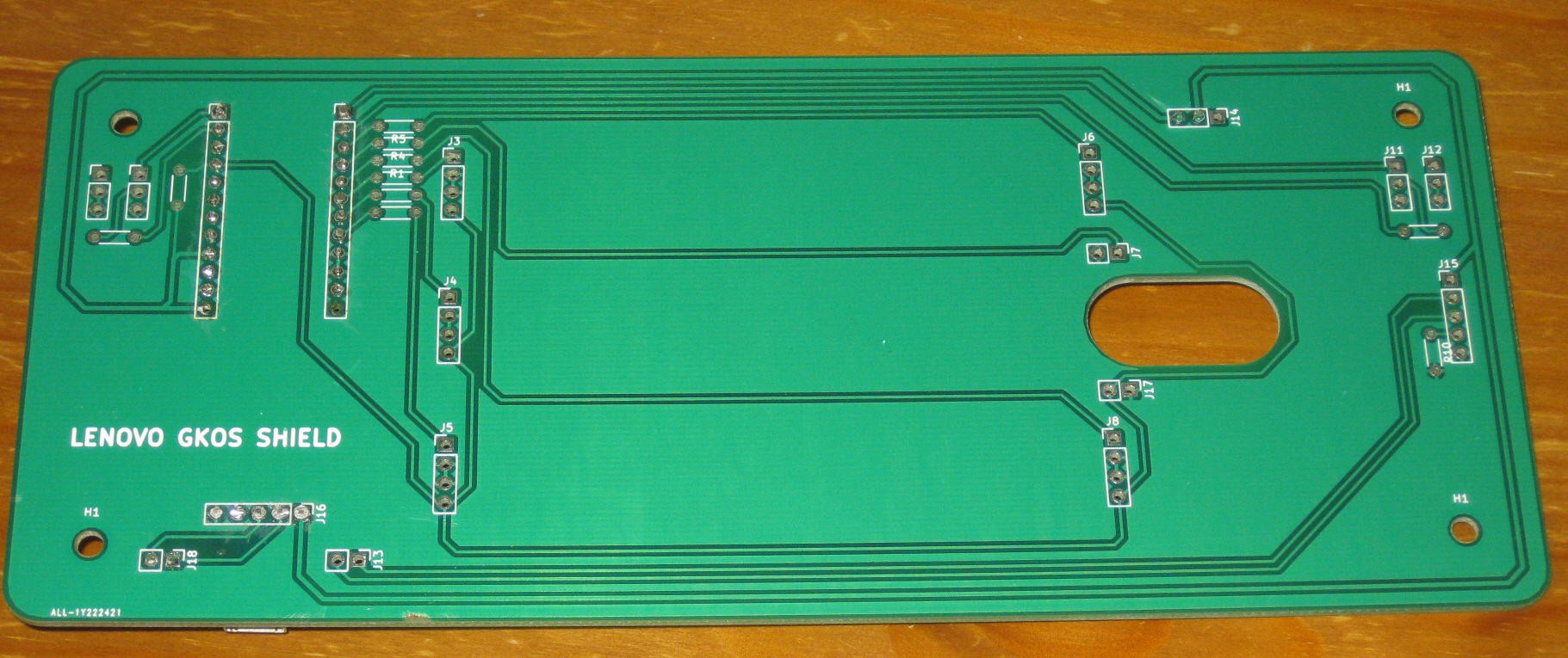
The PCBs are in excellent condition -- AllPCB quality, as always, very good:
![]()
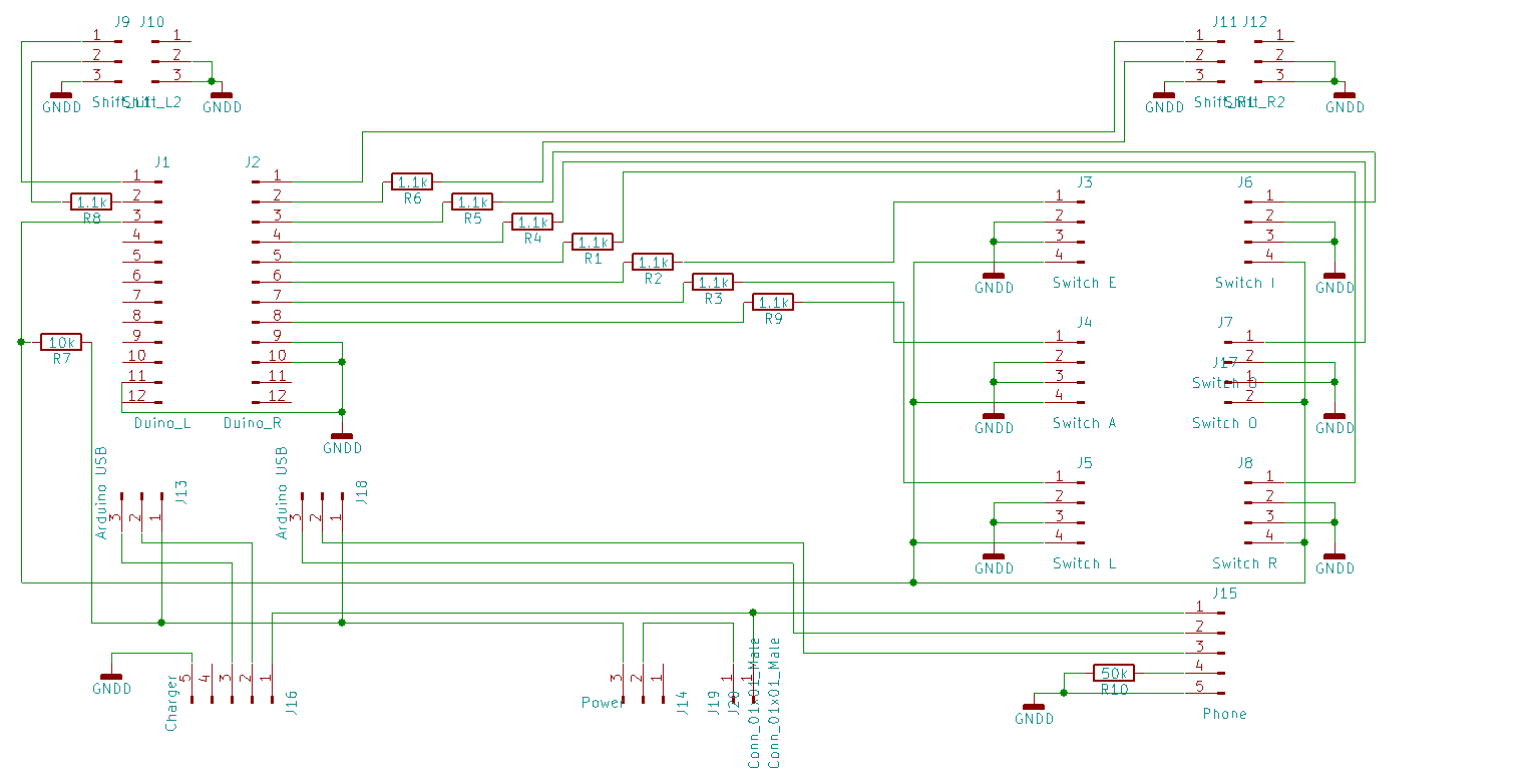
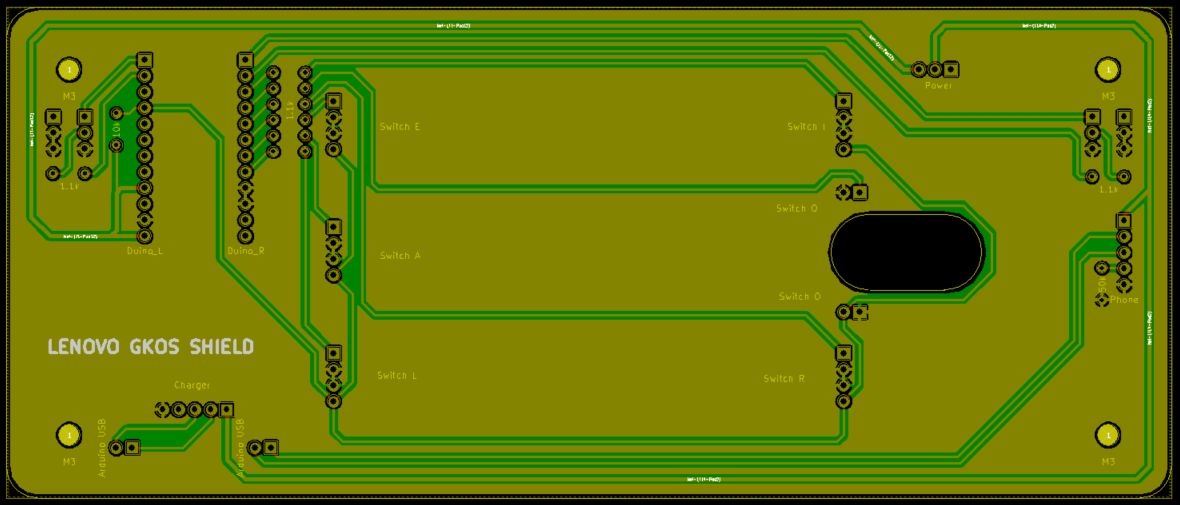
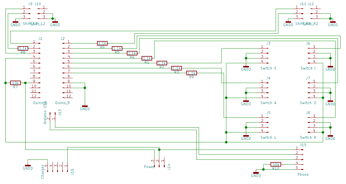
The final wiring diagram is as following:
Each of the 6 rear buttons has an optointerrupter, with the LED connected to the corresponding Arduino pin via a 1.1К resistor, and the photo-transistors connected to the pin 15 in parallel. The pin is pulled up by 10K resistor. To test a certain button, Arduino momentarily pulls up the control wire of corresponding LED, waits for 1 ms, then reads voltage on the pin 15. If the switch is "not closed" (that is no chopper between the LED and the photo-transistor) pin 15 will be low. If the switch is "closed", wire will be high. After switching the LED off, Arduiono further waits 1 ms, so the photo-transistor can lock completely, after that, the next button is tested, and so on.
I preferred this method over constantly shining LEDs on the photo-transistors, as only one LED is lit at the time, thus the LED power consumption is 2 mA instead of 12.
In the original PCB I made a mistake wiring 5V to the Arduino directly and not through the USB port. It was discovered that without 5V on the USB pin 1 Arduino Micro Pro does not connect to the PC. I fixed this by soldering the 5V wire to the board and cutting the trace to Arduino pin.![]()
Another minor issue was the power switch position, which was too far from the PCB edge. I fixed it by adding some extra wires to the switch.
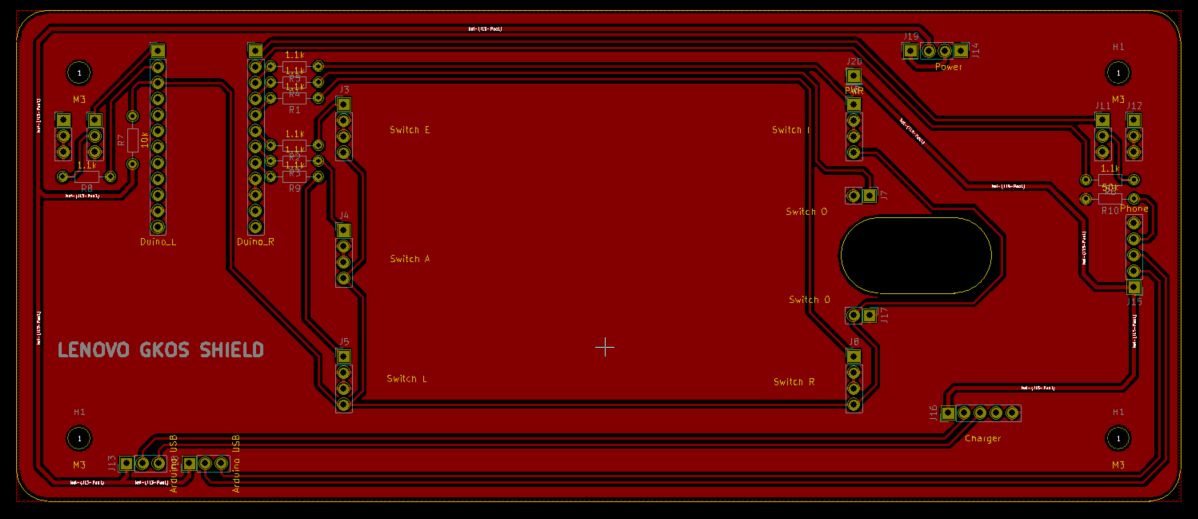
The updated PCB version: -
Initial PCB Design
05/31/2018 at 00:07 • 0 commentsToday I got my first parts from China and so can make some PCB decisions. The second prototype requires only one-sided board. Tracing is done in KiCAD
-
Second Prototype Printed
05/26/2018 at 11:57 • 0 commentsBased on the evaluation from of the first prototype, the 12 mm dome switches have been scrapped.
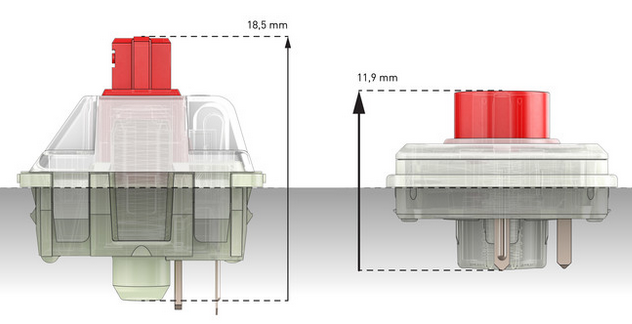
I gave a quick check to new Cherry MX low profile RGB:
These are made for laptop keyboards and exceptionally good, but 11.9 mm height is a bit thick for a tablet or phone. Maybe, next project.
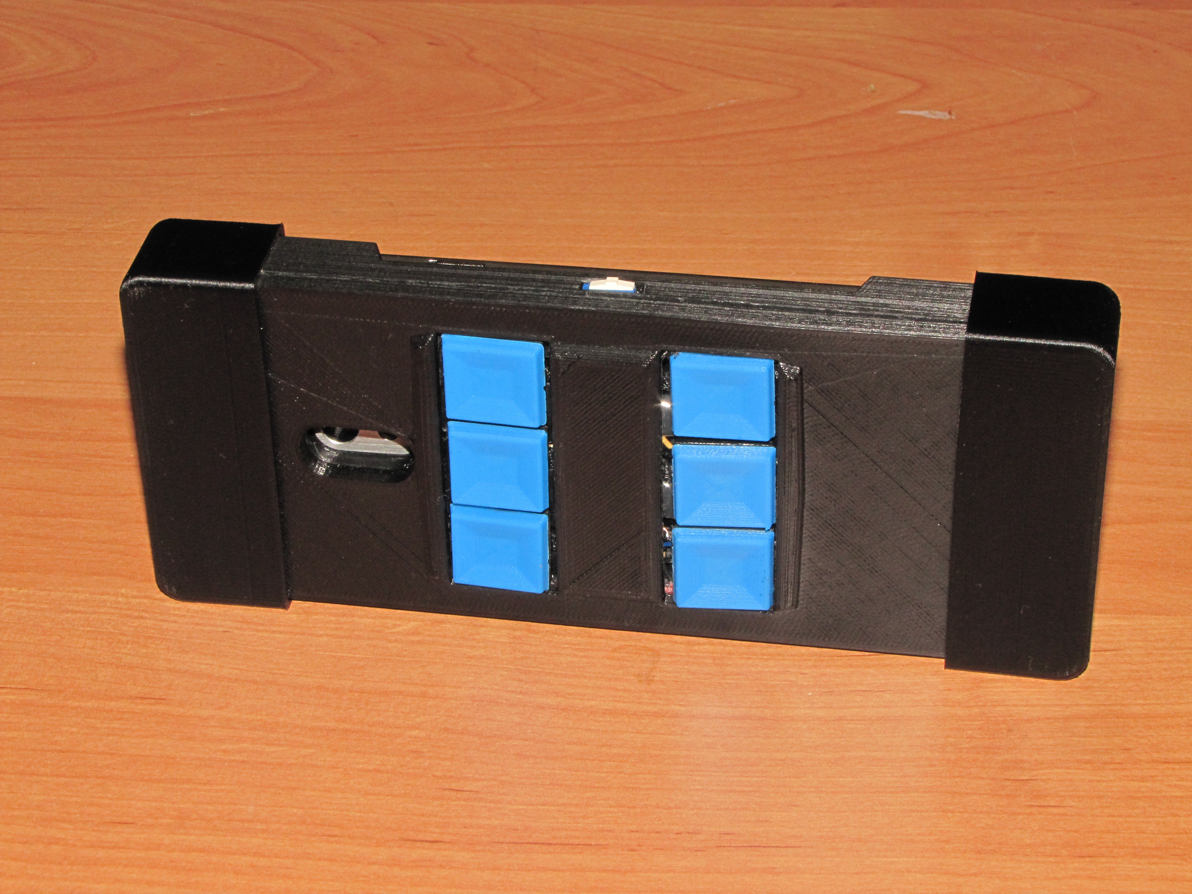
The second prototype is based around the 6x6 dome switches, which are much lighter than the 12x12 -- only between 15 and 18 gram force is required for closure. Above the switches, a hinged button is installed. I also finalized the cradle horizontal dimensions and the placement of the thumb Shifters. For faster prototyping, there is no PCB (and a lot of wires and hot glue) in this version.
![]()
The switches are covered with hinged caps. This is different from the implementation of Vijay, who used the same switches covered with silicone push buttons and plastic covers (check https://hackaday.io/project/21175-tipo-braille-smartphone-keypad)
![]() Finally, my second working prototype looked like this. And yes, the draft of this text was typed into the phone! (Upright view)
Finally, my second working prototype looked like this. And yes, the draft of this text was typed into the phone! (Upright view)![]()
The case is made of two half-shells, two handles, and six buttons, all printed (for now) with PLA. Printer step is 0.2 mm, takes about 6 hrs in total for all parts. Note that I messed the charging port hole slightly and had to do a quick fix with molten filament. Two holes in the bottom are for the buttons' hinges.
(Back side view)
![]()
Top of the cradle has a separate switch for the keyboard. The phone can be charged while in the cradle. If the charger is inserted, the keyboard is always on, independent of the switch.
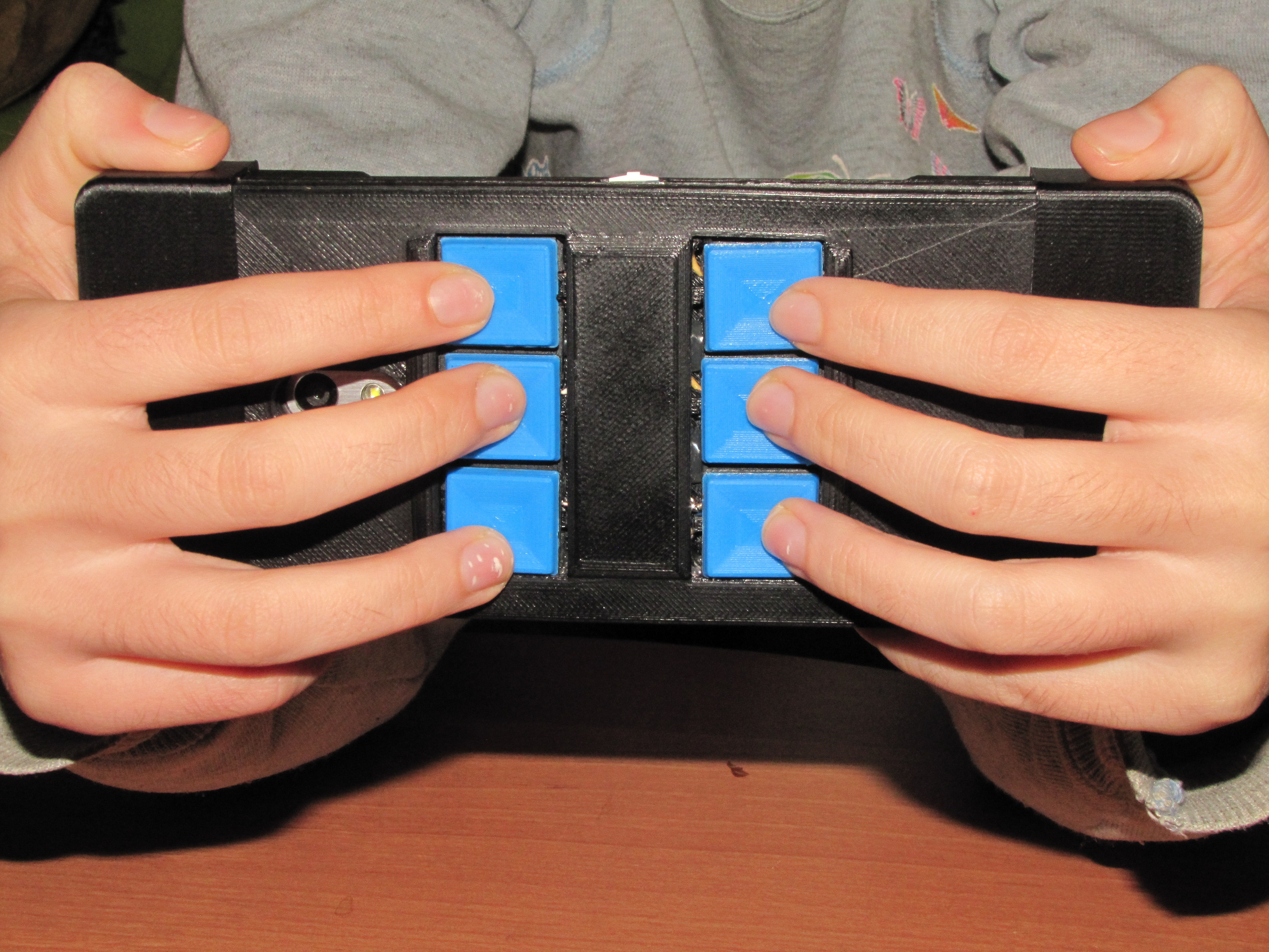
While typing the phone is held predominantly in a horizontal position as shown here:
![]()
The buttons provide sufficient tactile feedback, so quick notes can be typed without constantly looking at the screen. Or even without looking at all. Of course, there are typos, but try this trick on an on-screen keyboard.
The prototype dimensions are 190x80x24 mm (including the handles). The cradle is 46 mm longer, 5 mm wider and 14 mm thicker than the selected phone. The initial testing indicates the length of 190 is comfortable for prolonged typing, and the user's hands don't overlap the screen. By using a PCB in the next prototype, the overall cradle thickness should be reduced to 18 mm, making it only 8 mm thicker than the phone.
As expected, the cheap 6x6 dome switches feel... well: cheap and uncomfortable. The mechanical key caps are far better than silicone pads (try typing on a TV remote!), but still don't have the tactile feedback of an MX Cherry. For now, I will "type the prototype" and wait on the photo-interrupters from Aliexpress. Yes, the next version will have an optical keyboard!
Before the parts arrive, there is an opportunity to do some testing and chase the bugs.
-
First Prototype
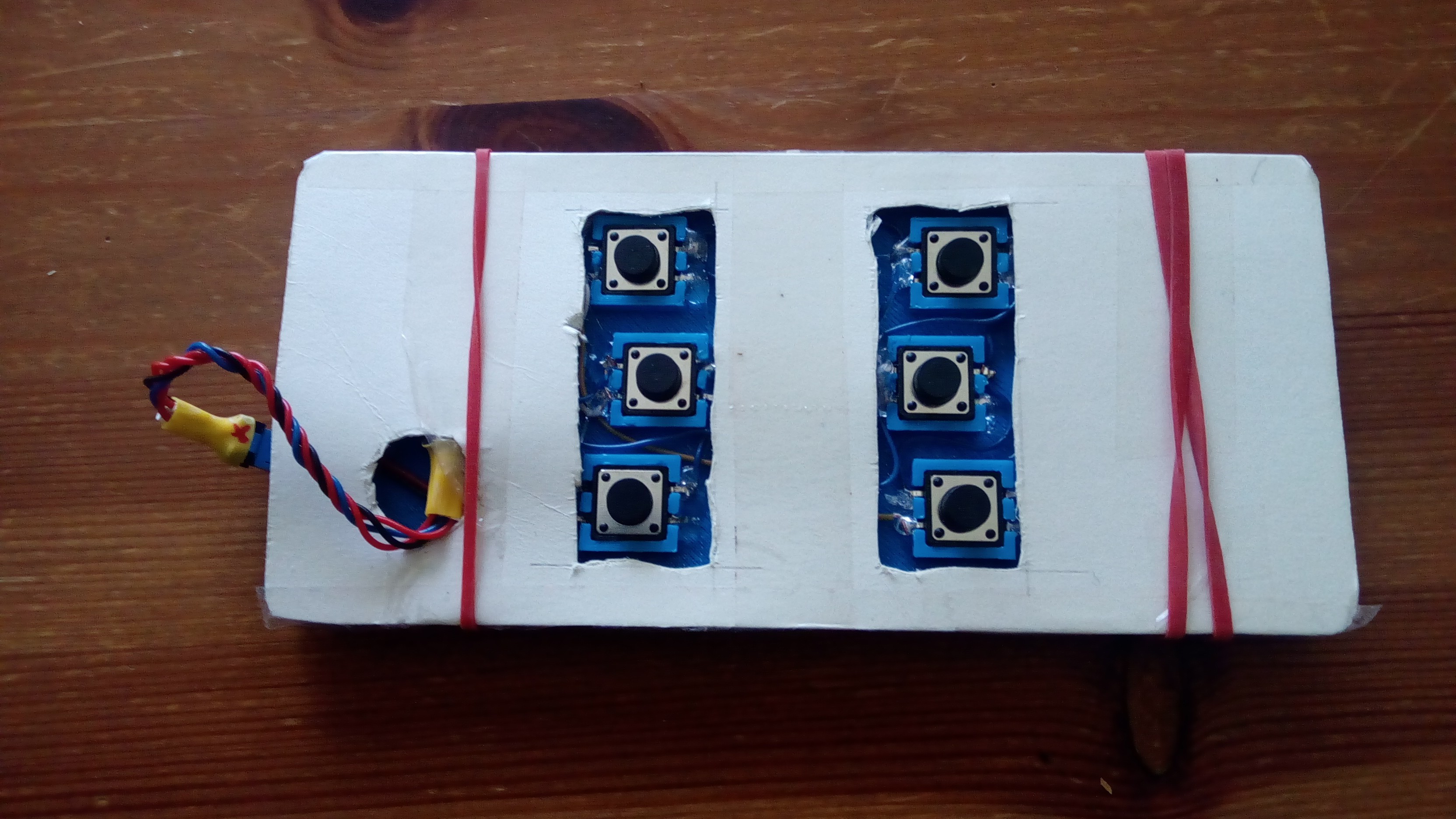
05/20/2018 at 05:00 • 0 commentsThe purpose of this was to check the software with real buttons and simultaneously evaluate the 12x12 mm tactile switches. A quick 3D print was made to hold the switches in the wanted positions:
![]()
The micro-USB wire connects the Pro Micro inside the enclosure with the phone port. The phone was held by two rubber bands. The schematics is as following:
The current version uses power from the phone. The 50k resistor between the USB lines 4 and 5 assures the phone can recognize the equipment on the other end of USB and send power. This is the same as an OTG cable. Lines 2 and 3 of the phone USB are connected to the same wires on the Arduino USB port, the power line 1 connects, via a slider switch, directly to the Arduino VCC. In the production version, the plan is to cut the Arduino own power regulator and use the USB power directly to reduce the power consumption (note that 5V Arduino is a must!)
A USB charger can be connected via a dedicated micro-USB port.
Arduino ports 16 and 9 control two front LEDs (integrated inside the Jaycar switches)
Ports 10 and 14 are the Shifters, ports 3-8 -- finger switches. Port 15 is reserved to the possible optical readout.
All four analogue ports and port 2 are not used (this is a potential mouse in the future).
In terms of software everything worked fine, but the tactile switches proved to be a wrong choice. Individually they press sharp and nice, with a pleasant audible click and good tactile feedback, but it proved to be difficult to hold three switches together at the same time: the total force on one switch is about 50 gram, far too much for prolonged typing. -
Completed programming
05/17/2018 at 04:28 • 0 commentsThe keyboard software is based on the quick-and-dirty GKOS keyboard I have tested earlier.
The major difference presently is the absence of a mouse/joystick - on an Android phone, I found the mouse pointer pretty useless anyway (this is rather a pun to the Android team, who gave the mouse functionality such a low development priority). The mouse can be added later if I decide on an Raspberry Pi build.
The keyboard operates in 5 modes:0 - normal (small letters)
1 - single capital letter, then switches back to mode 0. This mode is activated by the left Shifter press and indicated by the left LED.
2 - all capital letters. This mode is activated by the left Shifter double press and deactivated by the left Shifter. Left LED is lit (Probably will make it blink in the future).
3 - single symbol / number , then switches back to mode 0. This mode is activated by the right Shifter press. Right LED is lit.
4 - number mode. This mode is activated by the double right Shifter press. Both LEDs are lit. To cancel the mode back to 0, press any Shifter.
Additionally, the keyboard handles Russian alphabet, simulating the de-facto standard JCUKEN layout, so Android does not need to deal with any special phonetic keyboards. Arduino remembers if the current national layout has been activated and if the user moves to the "number" mode switches back to English. This way, the Russian "e" will not end up in the exponential numbers and such. After the number mode is deactivated, the national symbol mode is automatically restored.
The only additional (and optional) software on the mobile phone is the NULL Keyboard from wParam, available free on Playstore:
https://play.google.com/store/apps/details?id=com.wparam.nullkeyboard&hl=en_AU
It prevents the telephone on-screen keyboard popping up if one switches between input fields.
The current mode is implemented as following:
  bool modebutton = ReadPinBool( 7);
  if( modebutton && !GKOS_prevRight)
  {
    GKOS_prevRight = true;
    switch (GKOS_mode)
    {
      case 3:
        GKOS_mode = 4;
        #ifdef _DEBUG
        Serial.println( "Mode set to NUM");
        #endif
        break;
      case 4:
        GKOS_mode = 0;
        ForceRusLat( GKOS_prevRussian);
        #ifdef _DEBUG
        Serial.println( "Mode set to NORMAL");
        #endif
        break;
      default:
        GKOS_mode = 3;
        GKOS_prevRussian = GKOS_Russian;
        ForceRusLat( false);
        #ifdef _DEBUG
        Serial.println( "Mode set to SYMBOL");
        #endif
        break;
    }
    SetLEDs();
  }
  if( !modebutton && GKOS_prevRight) GKOS_prevRight = false;
  modebutton = ReadPinBool( 6);
  if( modebutton && !GKOS_prevLeft)
  {
    GKOS_prevLeft = true;
    switch (GKOS_mode)
    {
      case 0:
        GKOS_mode = 1;
        #ifdef _DEBUG
        Serial.println( "Mode set to SHIFT");
        #endif
        break;
      case 1:
        GKOS_mode = 2;
        #ifdef _DEBUG
        Serial.println( "Mode set to CAPS");
        #endif
        break;
      case 3:
        GKOS_mode = 4;
        #ifdef _DEBUG
        Serial.println( "Mode set to NUM");
        #endif
        break;
      case 4:
        GKOS_mode = 0;
        ForceRusLat( GKOS_prevRussian);
        #ifdef _DEBUG
        Serial.println( "Mode set to NORMAL");
        #endif
        break;
      default:
        GKOS_mode = 0;
        #ifdef _DEBUG
        Serial.println( "Mode set to NORMAL");
        #endif
        break;
    }
    SetLEDs();
  }
  if( !modebutton && GKOS_prevLeft) GKOS_prevLeft = false;
The whole sketch is in the project files. If somebody is interested, I can make an English-only version.
Mechanical GKOS keyboard for phones and tablets.
A no-compromise, mechanical switch, 6-button chording keyboard, placed on the rear side of a tablet or a mobile phone.
 Each of the 6 rear buttons has an optointerrupter, with the LED connected to the corresponding Arduino pin via a 1.1К resistor, and the photo-transistors connected to the pin 15 in parallel. The pin is pulled up by 10K resistor. To test a certain button, Arduino momentarily pulls up the control wire of corresponding LED, waits for 1 ms, then reads voltage on the pin 15. If the switch is "not closed" (that is no chopper between the LED and the photo-transistor) pin 15 will be low. If the switch is "closed", wire will be high. After switching the LED off, Arduiono further waits 1 ms, so the photo-transistor can lock completely, after that, the next button is tested, and so on.
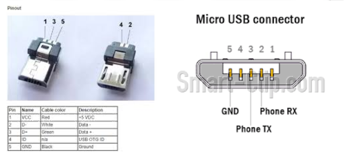
 These are made for laptop keyboards and exceptionally good, but 11.9 mm height is a bit thick for a tablet or phone. Maybe, next project.
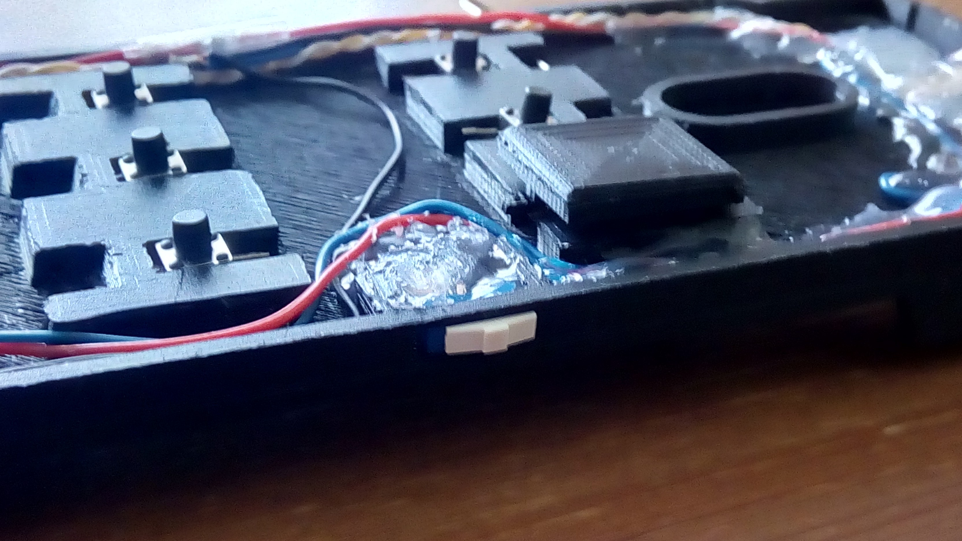
 Finally, my second working prototype looked like this. And yes, the draft of this text was typed into the phone! (Upright view)
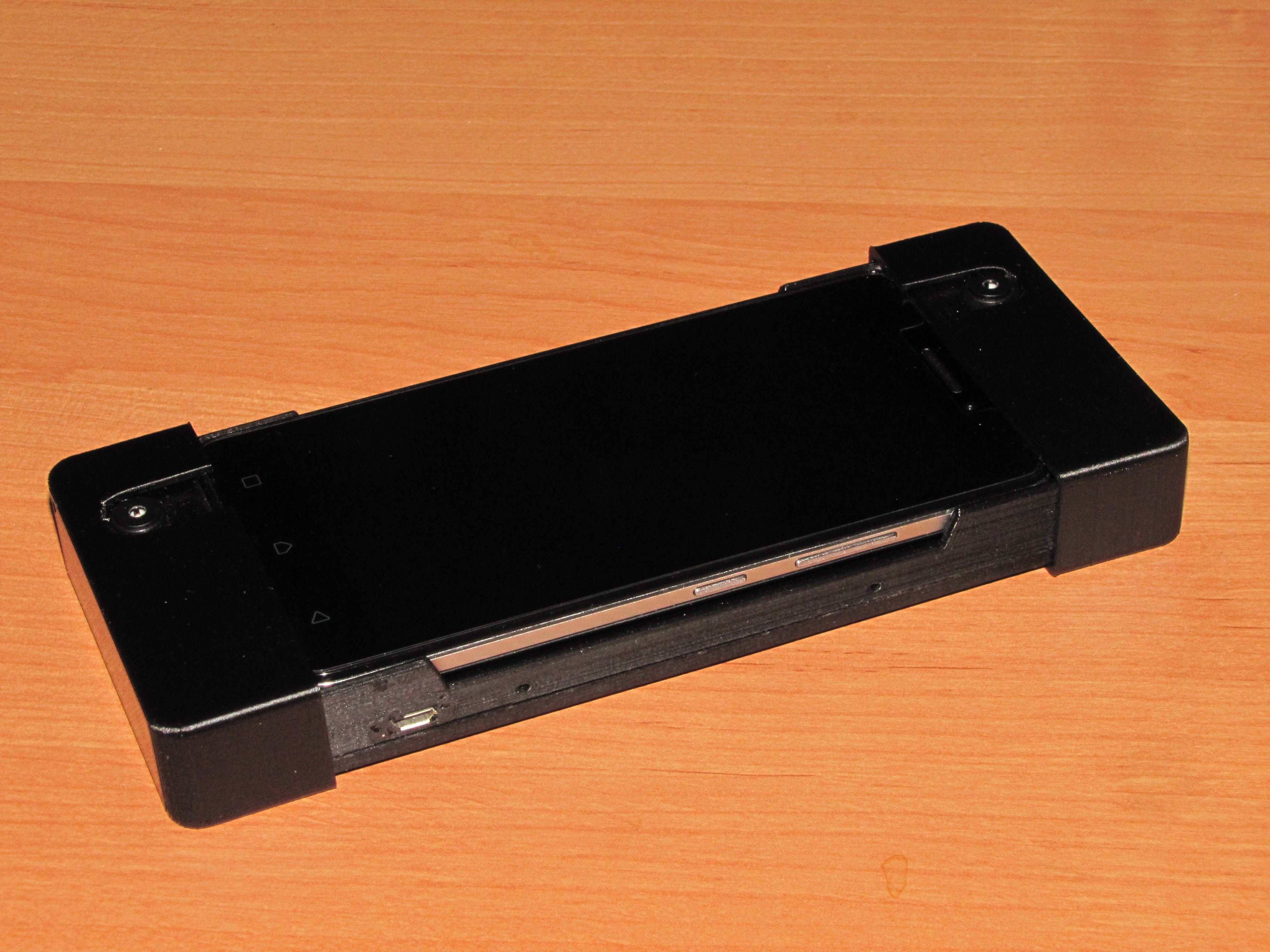
 The current version uses power from the phone. The 50k resistor between the USB lines 4 and 5 assures the phone can recognize the equipment on the other end of USB and send power. This is the same as an OTG cable. Lines 2 and 3 of the phone USB are connected to the same wires on the Arduino USB port, the power line 1 connects, via a slider switch, directly to the Arduino VCC. In the production version, the plan is to cut the Arduino own power regulator and use the USB power directly to reduce the power consumption (note that 5V Arduino is a must!)