SHAOS
SHAOS-
Servo test
06/04/2018 at 10:49 • 0 commentsHere I use cheap servo MG995 - I'm trying impulses 0.5ms, 1.0ms, 1.5ms, 2.0ms and 2.5ms (last one looks like too long for this servo) with total period of 20ms (and repeat every stage for 50 times to make it 1 second):
On the video you can see nedoCPU-16 board with nedoSerial interface connected to PC through USB-to-Serial adapter (on the left you can see terminal window). Behind there is a lab power supply that shows current and voltage that goes to servo and black power supply on the right gives 13.8V to nedoCPU-16 that has 7805 voltage regulator on-board.
Source code of the test program (here I heavily use macros from shaos-p16.inc and PDBLv1-2A2.inc):
	processor pic16f870
	radix dec
	include "p16f870.inc"
	__CONFIG _CP_OFF & _DEBUG_OFF & _WRT_ENABLE_OFF & _CPD_OFF & _LVP_OFF & _PWRTE_ON & _WDT_OFF & _HS_OSC
	include "shaos-p16.inc"
	include "PDBLv1-2A2.inc"

temp	equ	0x7E

wait	equ	17

	ORG 0
	goto Start

	ORG 4
	retfie

Start:
	_bank1
	movlw	b'00000000'
	movwf	TRISA^0x80
	_bank0
	_serial_print_ok
	_serial_print_nl
	clrf	PORTA
	_delay_ms 4,0

loop:

	_serial_send_ '0'
	_serial_send_ '.'
	_serial_send_ '5'
	_serial_print_nl
	_movlr 50,temp
loop_0_5:
	_movlr 0x20,PORTA
	_delay_us 500
	_movlr 0x00,PORTA
	_delay_ms 0,2
	_delay_us 500
	_delay_ms 0,wait
	decfsz	temp,f
	goto loop_0_5

	_serial_send_ '1'
	_serial_send_ '.'
	_serial_send_ '0'
	_serial_print_nl
	_movlr 50,temp
loop_1_0:
	_movlr 0x20,PORTA
	_delay_ms 0,1
	_movlr 0x00,PORTA
	_delay_ms 0,2
	_delay_ms 0,wait
	decfsz	temp,f
	goto loop_1_0

	_serial_send_ '1'
	_serial_send_ '.'
	_serial_send_ '5'
	_serial_print_nl
	_movlr 50,temp
loop_1_5:
	_movlr 0x20,PORTA
	_delay_ms 0,1
	_delay_us 500
	_movlr 0x00,PORTA
	_delay_ms 0,1
	_delay_us 500
	_delay_ms 0,wait
	decfsz	temp,f
	goto loop_1_5

	_serial_send_ '2'
	_serial_send_ '.'
	_serial_send_ '0'
	_serial_print_nl
	_movlr 50,temp
loop_2_0:
	_movlr 0x20,PORTA
	_delay_ms 0,2
	_movlr 0x00,PORTA
	_delay_ms 0,1
	_delay_ms 0,wait
	decfsz	temp,f
	goto loop_2_0

	_serial_send_ '2'
	_serial_send_ '.'
	_serial_send_ '5'
	_serial_print_nl
	_movlr 50,temp
loop_2_5:
	_movlr 0x20,PORTA
	_delay_ms 0,2
	_delay_us 500
	_movlr 0x00,PORTA
	_delay_us 500
	_delay_ms 0,wait
	decfsz	temp,f
	goto loop_2_5

	goto loop

	END
It works stable only if servo and microcontroller use separate power sources (and common ground of course)...
-
Public Domain Bootloader PDBLv1
06/03/2018 at 21:17 • 1 commentA little more about my "Public Domain Boot Loader" PDBLv1 which source code could be found right here in the file section of this project:
https://cdn.hackaday.io/files/1584186777755712/PDBLv1.c
It was written in C programming language in November 2011 to accelerate software development for PIC simulator of #3niti alpha ternary computer that was built around PIC16F870 (that has ability to re-write its own program programmatically from the code onboard). Source code was compiled into HEX by PICC 9.82.9453 lite (free version) under MPLABX IDE beta 7.12 that put all code at the end of available program space of PIC16F870:
https://cdn.hackaday.io/files/1584186777755712/PDBLv1.hexSo as you can see it takes space from address 0x2A2 and up (67% of program space - I know, it's a little bit too much) with GOTO 0x2A2 instruction at address 0x000. Bootloader takes control when you press RESET (or power-on your PIC16F870) and immediately after that send multiple ENTER keypresses to serial port with speed 9600 (8 bits, 1 stop bit and no parity) in less than 1 second after that (otherwise it will jump to address 0x001) then it will go in dialog mode with PDBLv1 prompt in your terminal:
PDBLv1
>
Available PDBL commands (all digits A and B below are hexadecimal):
!AAAA=BBBB - write word BBBB to program memory in address AAAA
!AAA=BB - write byte BB to data memory in address AAA
!AA=BB - write byte BB to EEPROM in address AA
?AAAA - read one word from program memory with address AAAA
?AAA - read one byte from data memory with address AAA
?AA - read one byte from EEPROM in address AA
. - exit from bootloader and jump to address 0x0001Possible errors:
ERR01 - illegal hexadecimal digit was entered
ERR02 - character '=' is expected
ERR03 - enter is expected
ERR04 - attempt to write in protected region (bootloader code)User can write words into program memory and then jump to the code by sending dot to the terminal - bootloader will perform GOTO 1 where user should have entry point of user program. Because bootloader has a number of useful subroutines already as writing and reading of EEPROM, sending and receiving bytes from terminal and also initialization of peripherals user program my utilize it by direct calling those subroutines - for this particular built (that I called v1-2A2) actual addresses may be taken from this include file (that also includes useful macros):
https://cdn.hackaday.io/files/1584186777755712/PDBLv1-2A2.inc
For example this is interface to EEPROM reading subroutine of PDBLv1:
eeprom_read             equ     0x0385
; ARG:W RET:W USE:#70,#71

_eeprom_read MACRO A,B
        movf    A,w
        call    eeprom_read
        bcf STATUS,RP0
        bcf STATUS,RP1
        movwf   B
        ENDM

_eeprom_read_ MACRO A,B
        movlw   A
        call    eeprom_read
        bcf STATUS,RP0
        bcf STATUS,RP1
        movwf   B
        ENDM
1st macro (_eeprom_read) if argument A is a data register and 2nd macro (_eeprom_read_) if argument A is an actual number (argument B is always data register to store read byte). Also this INC-file lists data registers that PDBLv1 is using and also specify free data registers that user program can use:
; COMMON #70..#7D(14) free #7E,#7F
; BANK0 #20..#3B(27) free #3C..#6F
; BANK1 (0) free #A0..#BF
This knowledge is relevant only if user program uses PDBL subroutines. If not then it could be ignored because PDBL will give full control to user program if nobody invokes bootloader from terminal in the boot time and user program then can use all available data memory.
In order to simplify process of re-flashing the PIC I wrote a program for Windows/MacOS/Linux that uses PDBL commands and sends HEX program to the PIC word by word (with verification):
https://cdn.hackaday.io/files/1584186777755712/pdbl1hex.c
PDBL makes sure that written program occupies only free space between 0x001 and 0x2A1 (and 1st GOTO is moved from address 0x000 to address 0x001 in order to co-exist with bootloader that takes control on every reset). Process of filling all available program space takes about 1m25s and from PC side it looks like this:> pdbl1hex t1_test3.hex pdbl1hex v1.1 sends HEX-file to the PDBLv1 device HEX 't1_test3.hex'... HEX Ok Opening /dev/ttyS0 PDBLv1 device detected Programming... oooooooooooooooooooooooooooooooooooooooooooooooooooooooooooooooooooooo oooooooooooooooooooooooooooooooooooooooooooooooooooooooooooooooooooooo oooooooooooooooooooooooooooooooooooooooooooooooooooooooooooooooooooooo oooooooooooooooooooooooooooooooooooooooooooooooooooooooooooooooooooooo oooooooooooooooooooooooooooooooooooooooooooooooooooooooooooooooooooooo oooooooooooooooooooooooooooooooooooooooooooooooooooooooooooooooooooooo oooooooooooooooooooooooooooooooooooooooooooooooooooooooooooooooooooooo oooooooooooooooooooooooooooooooooooooooooooooooooooooooooooooooooooooo oooooooooooooooooooooooooooooooooooooooooooooooooooooooooooooooooooooo ooooooooooooooooooooooooooooooooooooooo Verification... oooooooooooooooooooooooooooooooooooooooooooooooooooooooooooooooooooooo oooooooooooooooooooooooooooooooooooooooooooooooooooooooooooooooooooooo oooooooooooooooooooooooooooooooooooooooooooooooooooooooooooooooooooooo oooooooooooooooooooooooooooooooooooooooooooooooooooooooooooooooooooooo oooooooooooooooooooooooooooooooooooooooooooooooooooooooooooooooooooooo oooooooooooooooooooooooooooooooooooooooooooooooooooooooooooooooooooooo oooooooooooooooooooooooooooooooooooooooooooooooooooooooooooooooooooooo oooooooooooooooooooooooooooooooooooooooooooooooooooooooooooooooooooooo oooooooooooooooooooooooooooooooooooooooooooooooooooooooooooooooooooooo ooooooooooooooooooooooooooooooooooooooo Program OK (669 words)
Any questions? ;) -
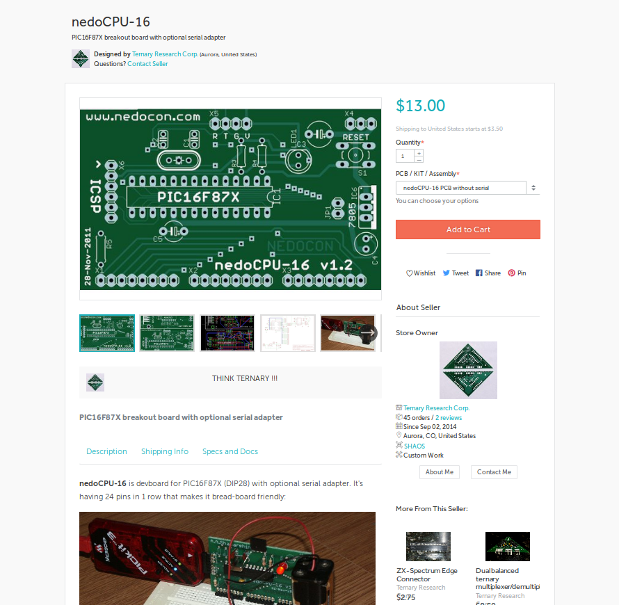
nedoCPU-16 PCB/KIT on Tindie
05/21/2018 at 23:14 • 0 commentsnedoCPU-16 board (multiple options from PCB to fully tested board with serial interface) is available on Tindie:
https://www.tindie.com/products/TRC/nedocpu-16/
![]()
-
2011 video of assembling nedoCPU-16
05/19/2018 at 01:53 • 0 comments10x time-lapse soldering of nedoCPU-16 prototype: