-
OCD: When Connections Don't Align
05/25/2018 at 00:15 • 0 comments![]()
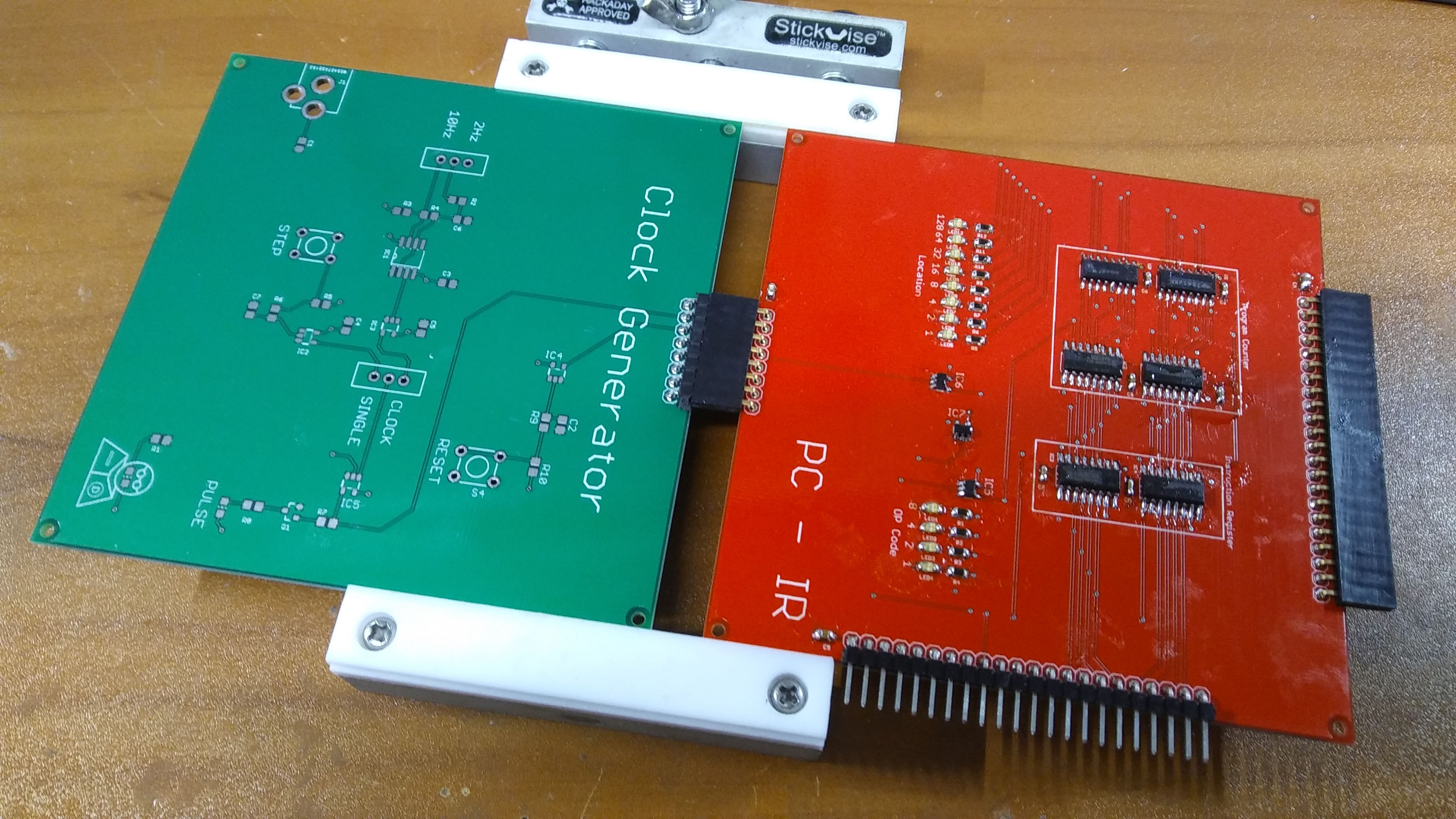
I am using some right angle male and female connectors to interface each of the modules. When the headers are at least 150mils (3.80mm) from the edge of the board, they "self-align" with the surface of the PCB. Unfortunately the connector to the Clock Generator Module on the PC-IR Module, was only 75mils from the edge, so it would not self align to the PCB. I went ahead and soldered the matching connector on the Clock Generator Module, and used my Hackaday Stick-Vise to align the two PCBs and soldered the header in place. This has been added to the "fix list" for revision B!
-
Decode: EEPROM Overkill
05/24/2018 at 03:19 • 0 comments![]()
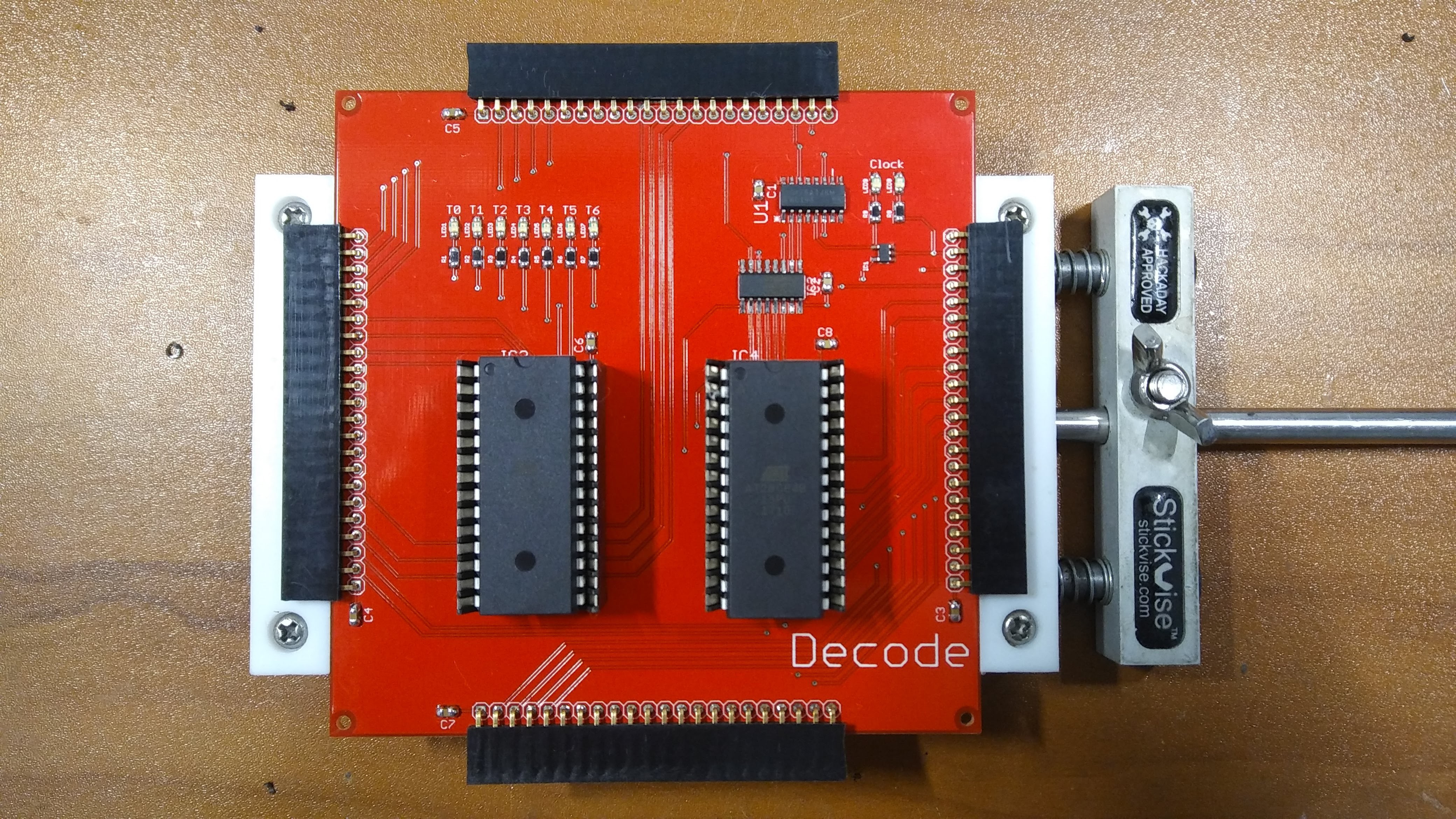
Two modules assembled... six to go! The Decode Module was the next easiest one to assemble, so I figured I would complete it this evening. It uses the same Low Insertion Force (LIF) sockets as on the ROM Module, as well as the same Atmel 8k x 8 eeprom. Using the 8k x 8 eeprom is extreme overkill for the decode module, however, since I was already purchasing some of the Atmel eeproms, I could use them for the Decode Module as well. I think in future versions I might go with a smaller eeprom, or even a small CPLD. This module consists of the two eeproms, a 74LVC193 4-bit counter tied to a 74LVC138 1-of-8 decoder. These two combine to control each of the 7 phases of the microprogramming. I've added LEDs to indicate the phase state as well as some LEDs to display the primary clock status. This module connects to 4 other modules, more than any other, so I decided to use female headers on all four sides.
-
ROM: Low Hanging Fruit
05/24/2018 at 01:41 • 0 comments![]()
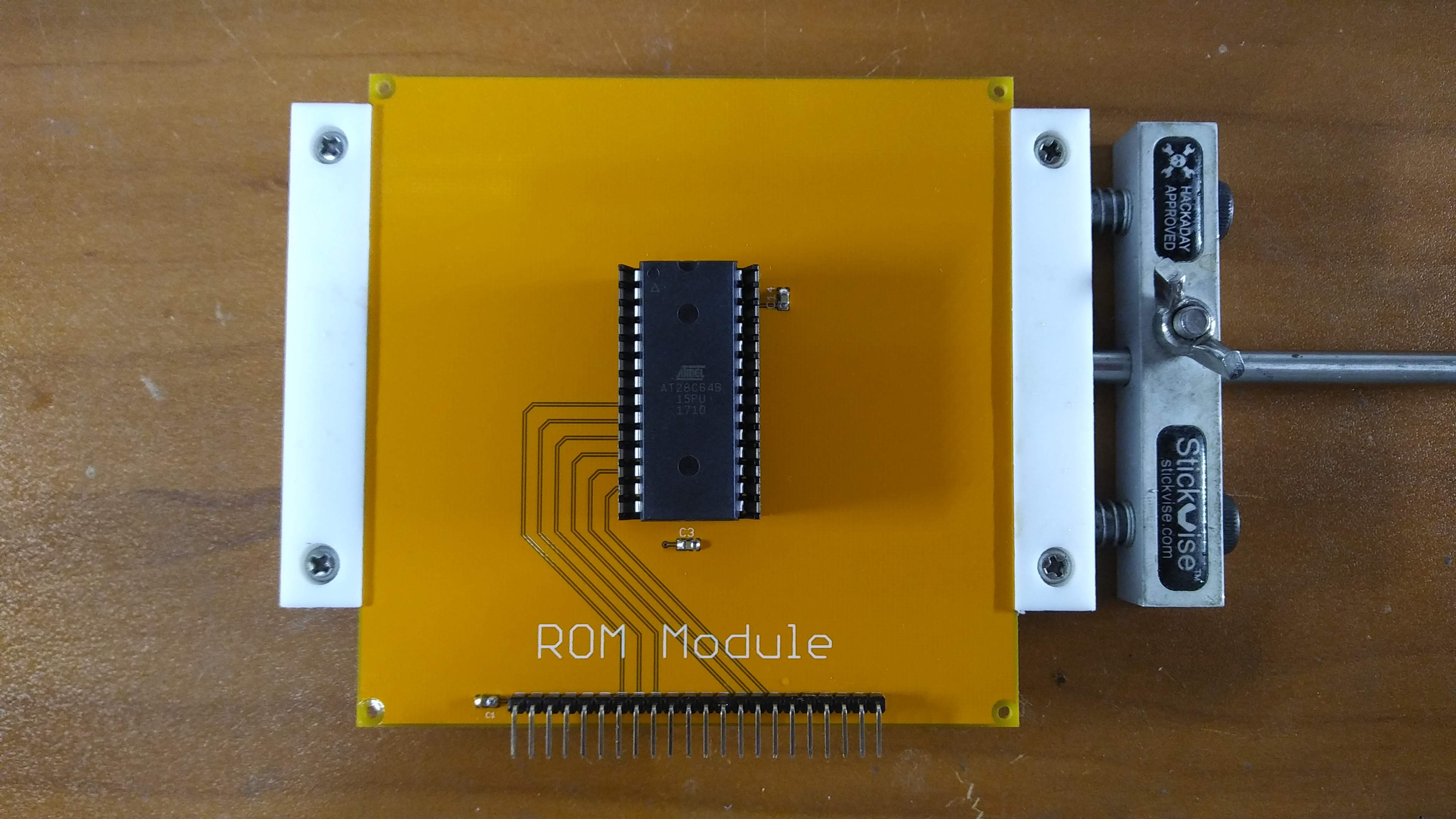
So all of the PCBs arrived yesterday, and all of the remaining parts arrived today.... time to begin assembly. When I started looking at the boards this evening, my original intention was to assemble the boards in a strict order with a log post for each, however, I succumbed to temptation and started with the simplest board: The ROM Module. The ROM Module only consists of three capacitors, the i/o header, and the ROM, so it was the lowest hanging fruit of the design. My intention was to populate the board with a standard socket, and then use a Zero Insertion Force (ZIF) socket on top of that, but after visiting my local surplus shop Tanner Electronics, I discovered they had some inexpensive Low Insertion Force (LIF) sockets. The price was right and they seemed to do the job, so I purchased 10 pieces. I will also be using these LIF sockets on the Decode Module. I've selected the Atmel AT28C64B-15SU EEPROM to use in this project. It's an 8k x 8 device, supported by most of the inexpensive eeprom programmers like the TL866 series which we will discuss in a later log post. In addition, they are relatively inexpensive, and available in quantity from retailers like Digikey and Mouser. One down... seven to go..
 Dave's Dev Lab

