AndreasVS
-
...more details
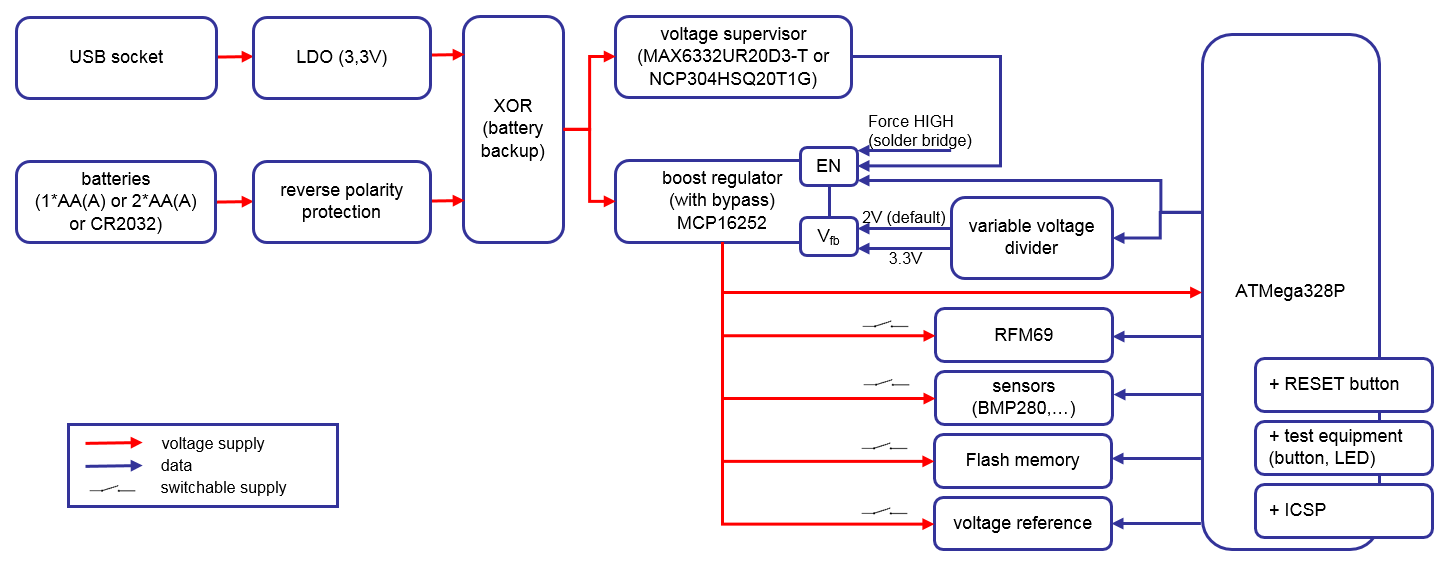
06/08/2018 at 15:00 • 0 commentsThis diagram shows more details than before, how everything should fit together. The focus - as before - is on the power supply.
![]()
The voltage of 5V from the USB socket will be decreased by the LDO (NCP1117), to be compatible with the rest of the circuit. The second kind of power supply (batteries) has only a reverse voltage protection (no LDO).
Both voltages come to the next component (XOR function), where only one power supply is let through. The USB power supply is prioritized and only if there is no 5V comming from the USB socket, then the battery voltage is used (like a battery backup). So, every other component in the circuit will either get a stable 3.3V supply or the unstable 0.9V to 3.xV power supply comming from one of the batteries.
The main idea for the next parts is to deliver a minimum voltage of 2V independent of the kind of supply. Only when needed, the booster will produce 3.3V. So the boost regulator is normaly disabled (bypass mode: Vin = Vout) . Only when the voltage from the battery supply is lower than 2V, the voltage supervisor will force the boost regulator to boost the voltage to 2V. When needed, the ATMega changes the voltage divider for the boost regulator so that it boosts the voltage to 3.3V.
Most parts (sensors, radio, voltage reference) can be switched off by the ATMega328.
-
Main Concept
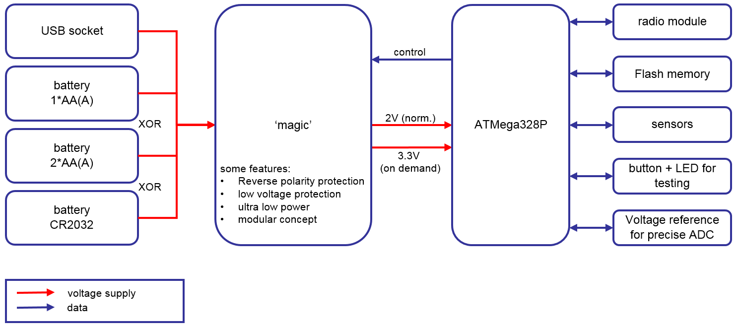
05/24/2018 at 09:48 • 0 commentsThe concept visualised from the birds view:
![]()
Power supply can be a USB-cable and/or one of the named battery solutions or maybe LiPos (all batteries = XOR). The CR2032-option has later to be tested if the internal resistance of the battery prevents the use of ATMega and RFM69. When battery powered, a reverse polarity protection protects the circuit. Using USB-power and battery at the same time is possible. In this case battery is used as a backup solution. An electronic circuit guarantees a minimum voltage of 2V.
The ATMega can control the power supply circuit so if it needs 3.3V for the additional components, it will be there.
With solder bridges it will be possible to influence the behaviour of the circuit (for example: FORCE_3V3).