The past week or so has given me a surprising amount of mental turmoil - more than a "fun" project like this should. Allow me to explain (or just skip ahead, because, fair warning - I'm going to ramble a bit here):
When I first started this project a couple of weeks back, I noted in the project description that the actual documentation of Instax teardowns, repair, and modification is surprisingly sparse considering the vast userbase. I attributed that to Instax's broad appeal to casual photographers, people who generally view such cameras as appliances first and foremost, without much interest to the aforementioned topics (and I don't mean that in a disparaging way at all - it is this low barrier to entry which is probably keeping this medium alive and well). But, as it turns out, there might be a little more behind this lack of information.
A week or so ago, I received a pointer from an acquaintance on Instagram regarding the film eject circuit I had drawn up and shared in a previous project update. As it turns out, there was an important element missing that would have rendered that circuit useless. It's likely that this pointer saved me a week or so of head scratching and retooling. But, this detail came with a caveat, namely that I was not to share that information, for fear of spawning clones and copycats.
Enter my recent cognitive dissonance - on one hand, I'm thankful for the advice and would like to respect the desire to keep such tribal knowledge, well, tribal. But on the other, I think that such knowledge would be incredibly useful for anyone trying to undertake a similar project to mine. I believe that there is so little substantive information about how to modify Instax cameras, that this in itself poses a major obstacle to people who would be excited to modify their cameras themselves. In the end, I've decided to do the latter - share this information freely at the risk of burning a bridge or two. Yes, I realize that there is some pride to having the one and only Instax camera with an X-Y-or-Z, and that some are able to monetize this hobby by employing the tribal knowledge of the ins-and-outs of Instax. But with a medium as mercurial and fleeting as instant photography, I think everyone should have a chance at building their own.
Okay, rambling over. Let's get to the good stuff!
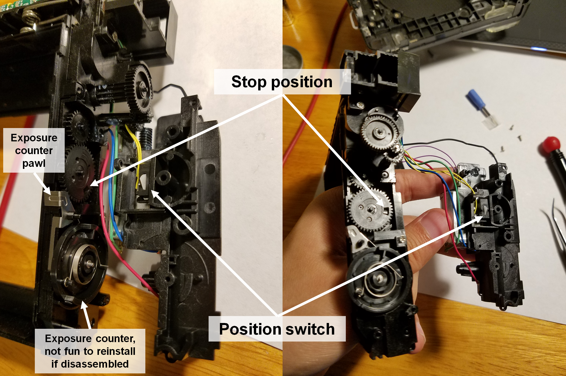
What I learned from my Instagram acquaintance is this: the film eject motor requires some degree of braking to avoid overrunning the position switch. Without braking, the motor will keep turning even after the position switch opens at the end of the cycle, and the camera will keep ejecting film continuously. You can see that the position switch fits into a small hole in a gear at the end of the cycle. If the motor is not braked after the switch opens, it will easily overrun this small window. I don't recommend taking apart this mechanism as shown below. It's a pain to get back together, especially the exposure counter part, which has a bunch of fiddly parts that are hard to seat correctly.
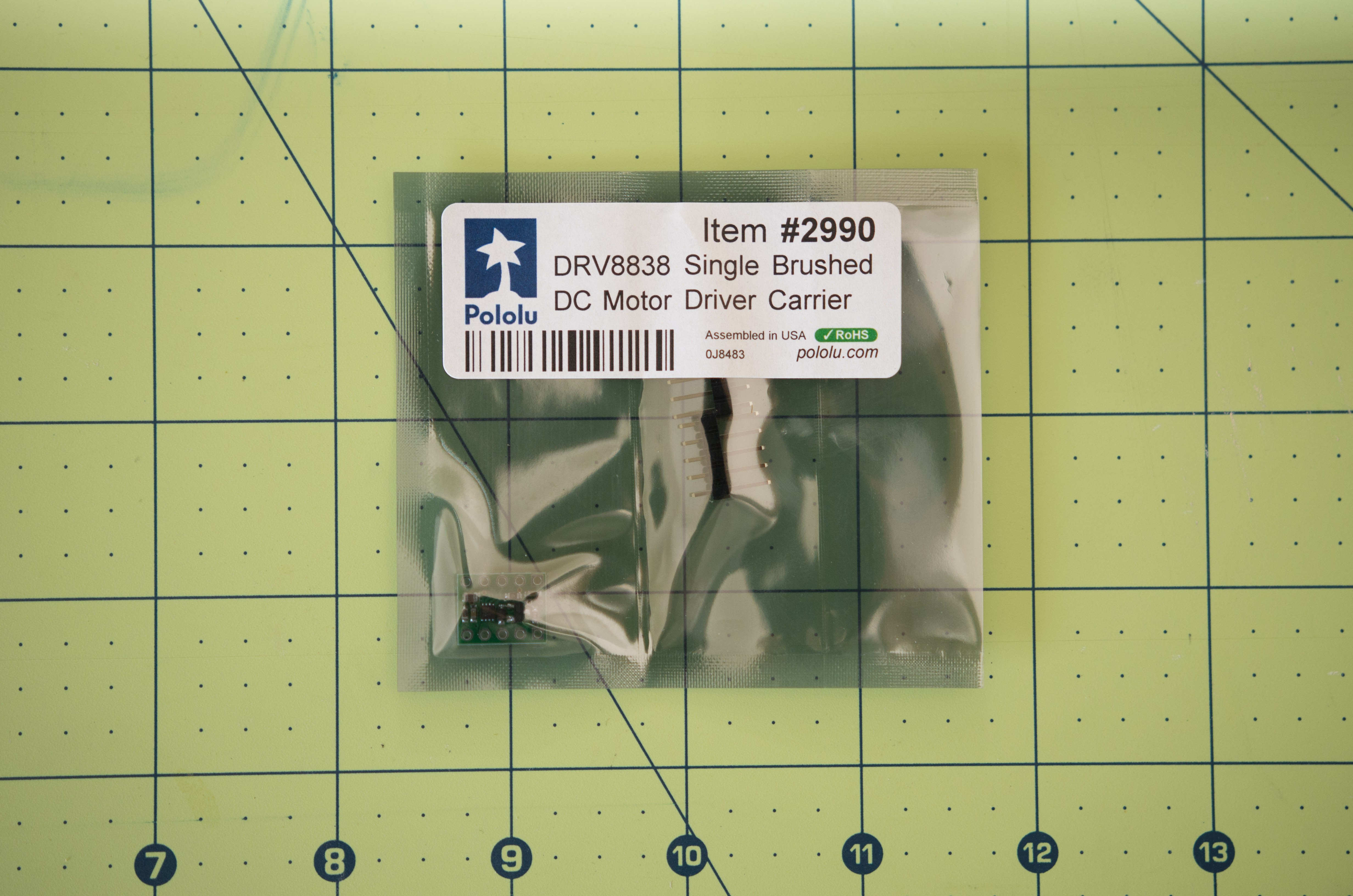
Thus, the simple MOSFET motor "control" in my original circuit was insufficient. When the motor is turned off, the terminals must be shorted to prevent it from coasting. By far the easiest way to do this is by using an H-bridge IC (also at the recommendation at my Instagram acquaintance). The motor looks to be a 130-size brushed motor, and at 6V I would assume the stall current to be around 1A (just a guesstimate). I opted to buy a couple of Pololu DRV8838 boards, which can drive a single DC motor up to around 1.8A. The general principle of the wiring from the simple MOSFET board remains the same:
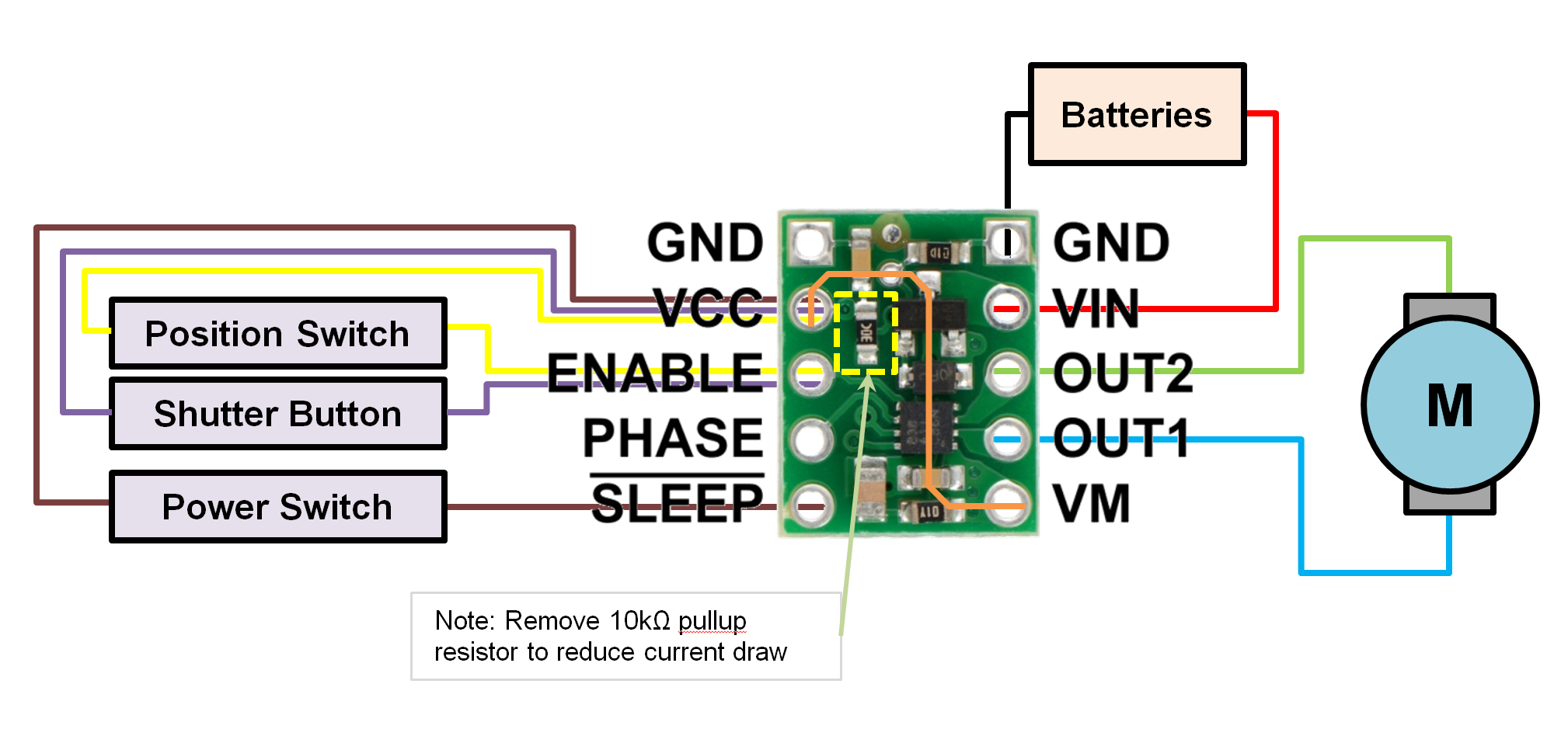
When the SLEEP pin is driven high when the power switch is closed, the driver is powered on and the motor brakes when not in motion. When the power switch is opened, the SLEEP pin goes low due to an internal pulldown resistor and the motor coasts, no longer drawing current. Unfortunately, Pololu adds a 10k pullup resistor to this line, which I recommend removing - this dramatically decreases the amount of "off" current drawn by the circuit.
Personally, I despise soldering through-hole and point-to-point. Four tiny wires from the camera need to be brought together and soldered to the VCC via, and this is a real pain in the neck. I've spun up a couple of new boards which break out each of these connections, to make life a bit easier. The tricky thing will be soldering the DRV8838, which is a 2 x 2 mm WSON package. The BOM for these boards is ~$5 USD, which is more than the Pololu board. But hey, purple PCBs look cool right?
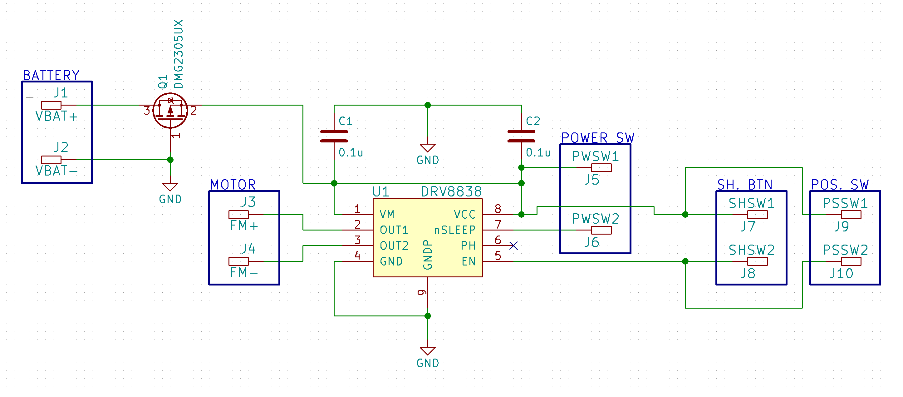
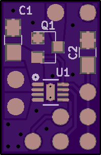
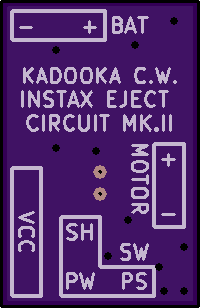
Those will take a week or two to come in and populate, so I went ahead with using the Pololu boards as a proof-of-concept. As I noted earlier, it's a bit of a messy operation, but I'll try to lay things out step by step.
First of all, make sure the batteries are removed from the camera. This is to help prevent an accidental short down the line. Next, desolder the battery connections to the main board:
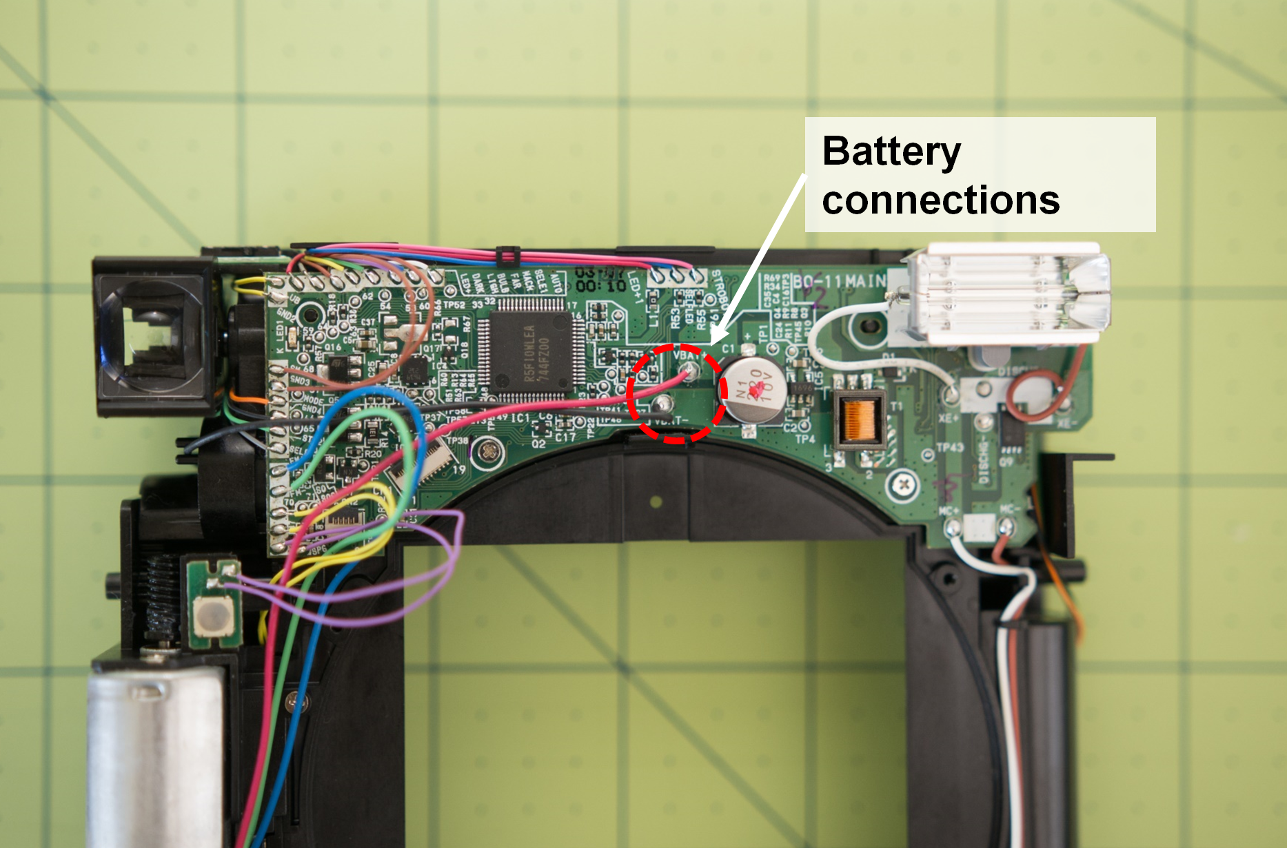
Next, desolder the relevant signal lines from the main board. These are:
- Shutter button (purple)
- Position switch (yellow)
- Power switch (brown)
- Eject motor (blue [positive], green [negative])
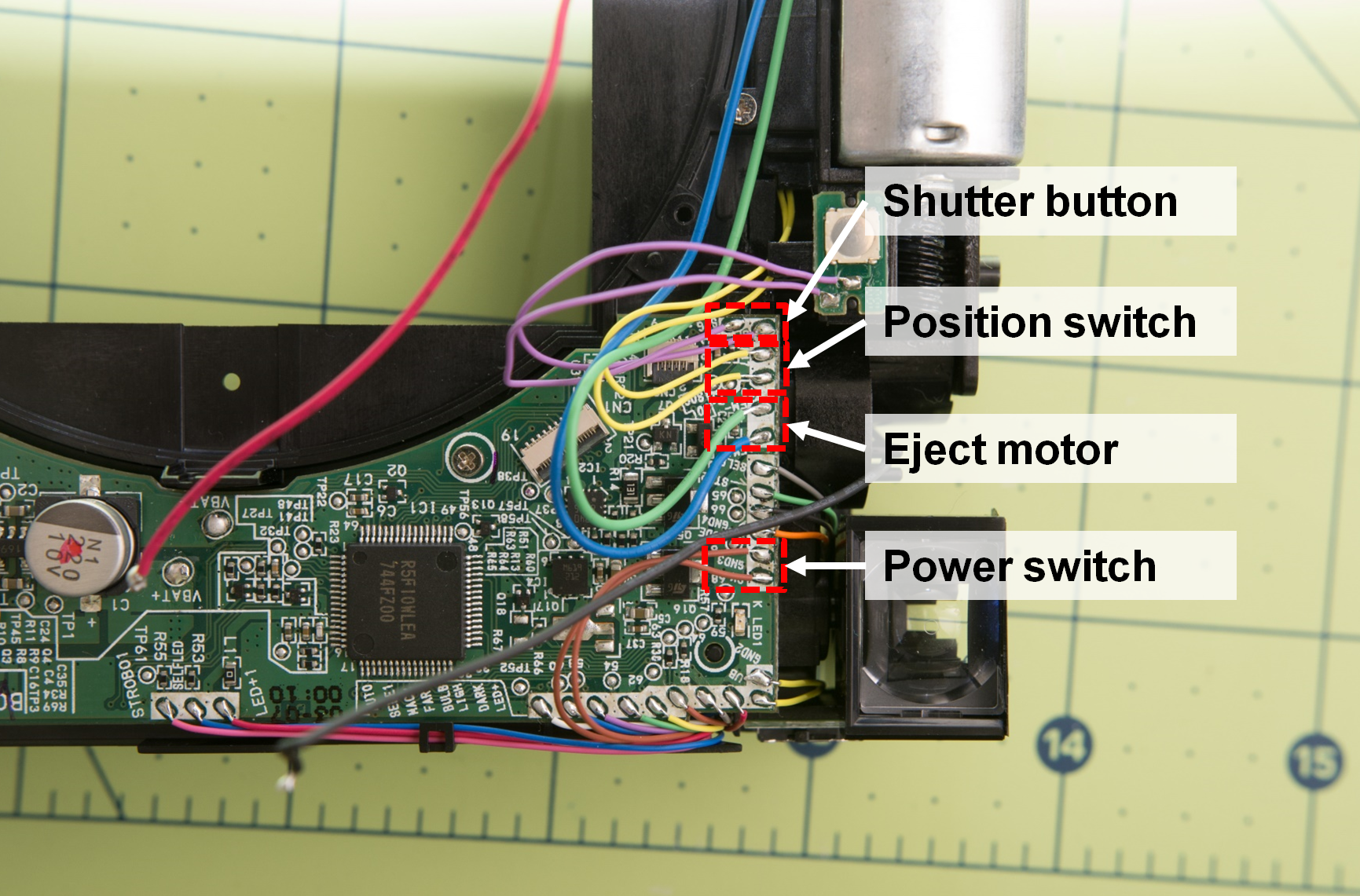
Now for the "fun" part. Solder the freshly disconnected connections back to the DRV8838 board as shown in the figure above. If you have not already removed the 10k resistor, do this now!
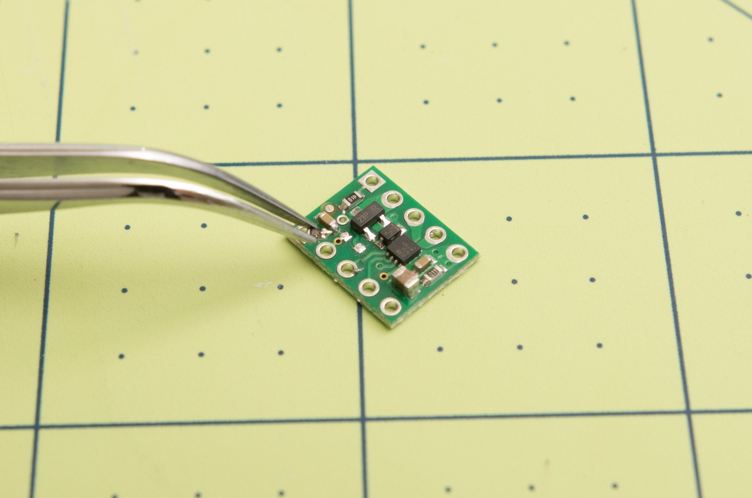
After you solder everything together, you'll have an ugly mess like this. Reason 1 of why I don't like soldering point-to-point...
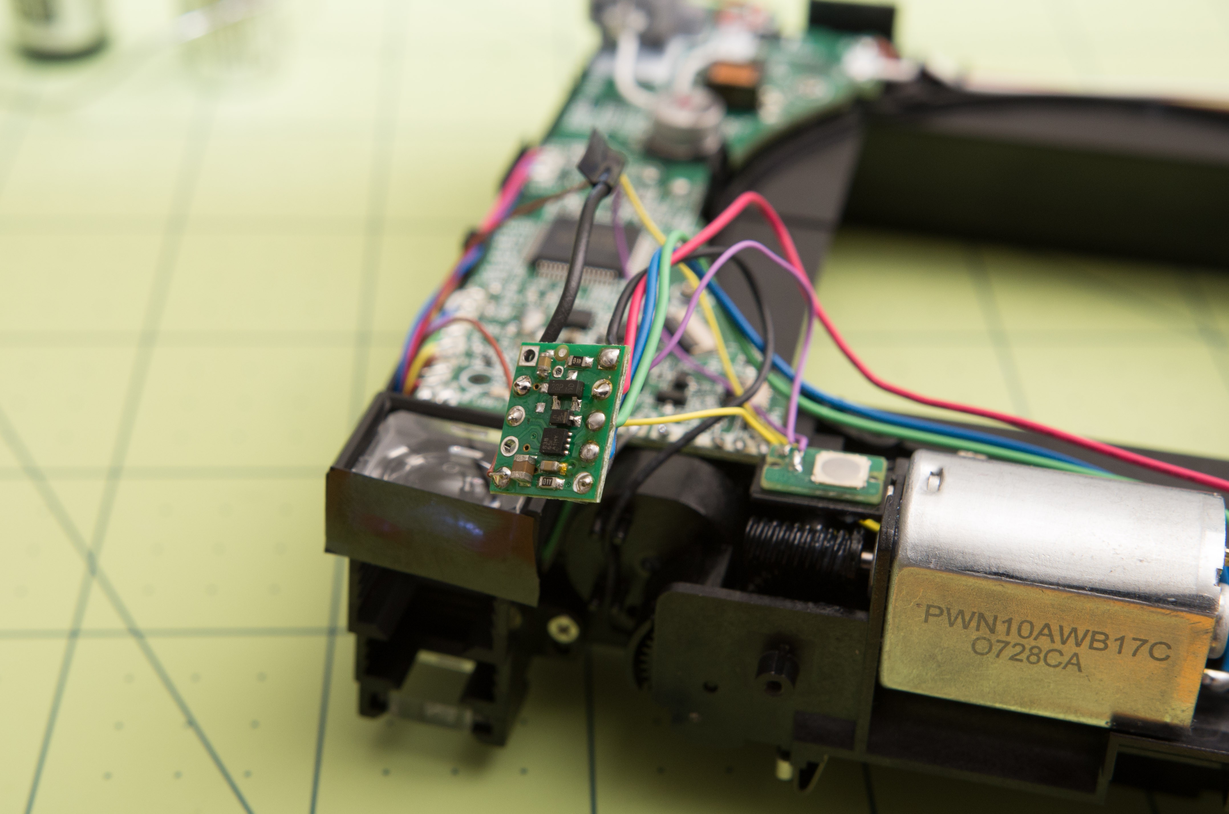
Finally, tidy up the wires and tuck the board just underneath the viewfinder assembly. You can now give the circuit a test - load up the batteries, flip the power switch on, and press and hold the shutter button for about one second. The motor should spring to life, and you should see the pick arm go through one cycle, and then stop.
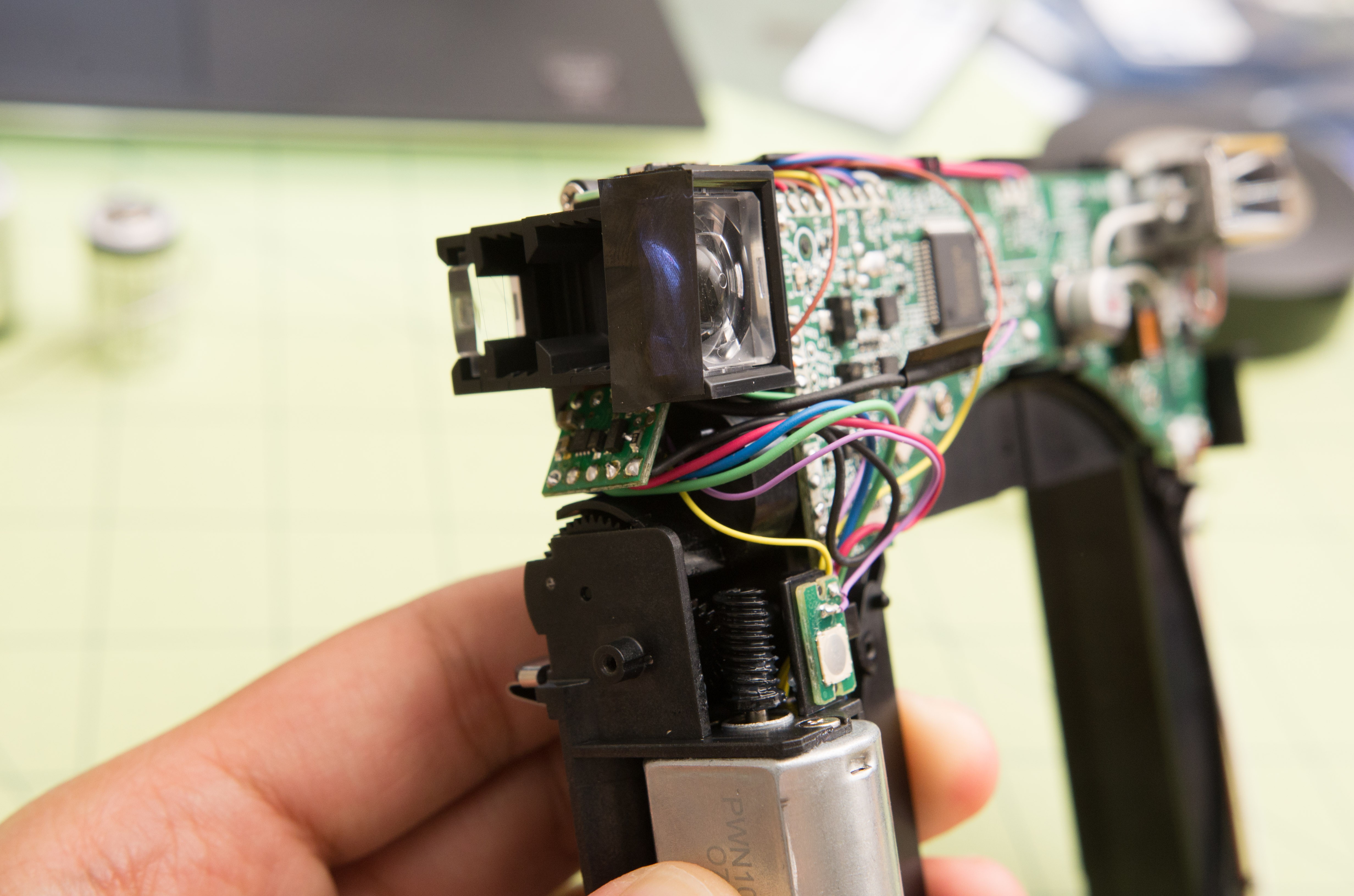
Now, you have a camera that ejects film on cue. Coming into this project, for me, this was the most cryptic part. I hope this helps to solve some burning questions, and I hope that at the same time I haven't managed to burn too many bridges :)
Coming up next time - mounting the lens and focus calibration.
 Kevin Kadooka
Discussions
Become a Hackaday.io Member
Create an account to leave a comment. Already have an account? Log In.
Great job Kevin
Could you please send the update about mounting the lens and focus calibration.
I ordered the parts and 3d prints.
Waiting for that part
Many thanks
Mason
Are you sure? yes | no
I think you're doing the right thing by sharing the information.
Are you sure? yes | no
camera's looking great, I really appreciate you sharing the details. I'm inspired to make my own, thanks!
Are you sure? yes | no