-
1Getting the board
The board comes in two variants: standard and mini. The standard variant has 12 channels, and supports 3 RGB lights + 3 white lights. The mini variant only supports 1 RGB light + 1 white light. The KiCad project files can be found here for the standard variant, and here for the mini variant.
The mini board is 83 mm x 71 mm, whereas the standard board is 159 mm x 71 mm. Because the mini board is smaller than 100 mm x 100 mm, it's much cheaper to get the mini boards made.
Gerbers for both variants are available in the Files section of this project.
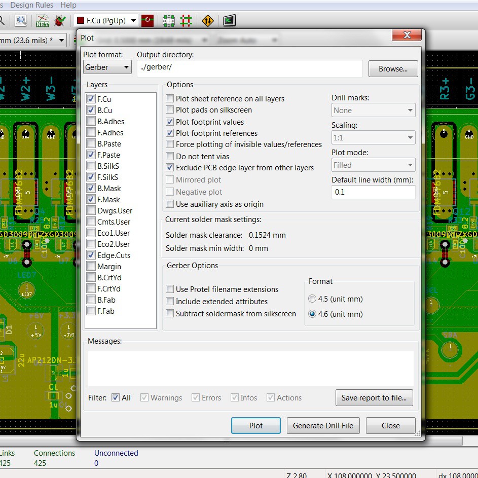
Gerbers can also be generated using KiCad (I used version 4.0.7). If you haven't used KiCad before, this is usually done by opening the project in KiCad, opening Pcbnew, selecting "File"..."Plot". Here are some typical settings:
![]()
Clicking "Plot" and then "Generate Drill File" (then clicking "Drill File" in the dialog box that pops up) will dump all the gerbers in the specified output directory.The gerbers can be sent to the PCB fabrication place of your choice. The board has quite relaxed requirements: minimum 0.2 mm track spacing, 0.254 mm track width and 0.6 mm diameter holes.
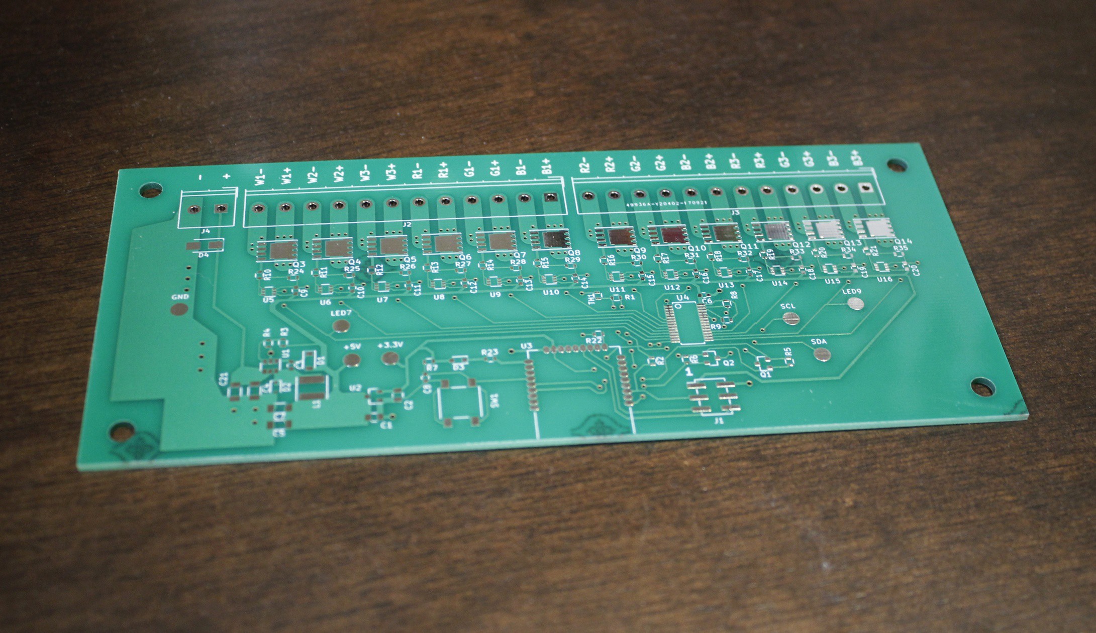
The exact procedure for gerber file submission depends on the fabrication house; you'll have to carefully follow their instructions. If all goes well, you end up with:![]()
-
2Getting the components
The BOM (in .xlsx format) can be found here for the standard variant, and here for the mini variant. The BOM contains exact manufacturer part codes for all components. However, depending on when you are reading this, some of those parts will probably be out of stock. For most of the resistors and capacitors, substitution with another part of the same value is possible - see the "Notes" column for restrictions on substitution.
-
3Assembling the board
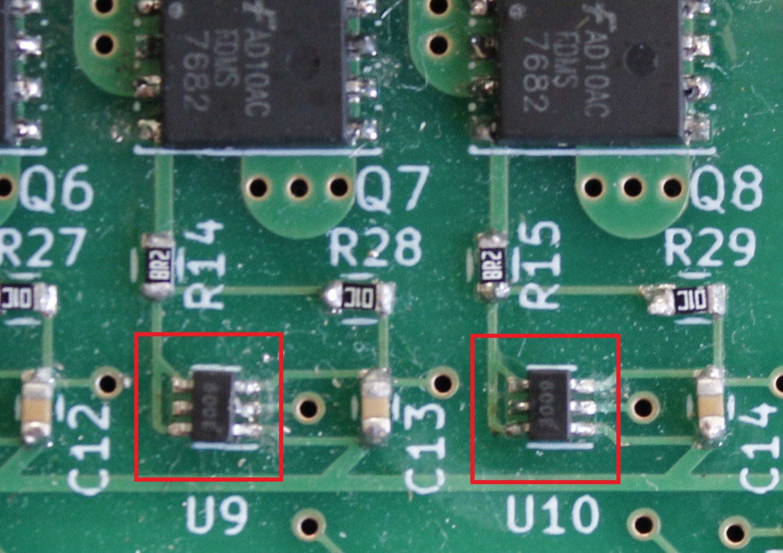
The orientation of most of the components can be determined by their footprint. However, there are a few difficult parts. On standard-variant boards, the ZXGD3009 should be oriented so that the barely-visible "3009" reads in the same direction as the R14/R15 etc. designations, like this:
![]()
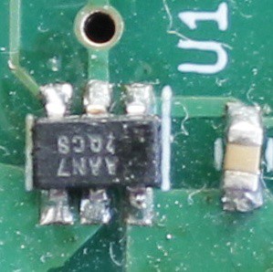
On both variants, the MCP16301 has a tiny pin 1 mark that should be placed next to the longer line on the silkscreen. Alternatively, the text on the chip should read so that the "U1" designator is to the left of the text (i.e. the text is upside-down compared to the rest of the silkscreen text on the board):
![]()
![]()
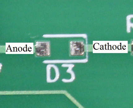
All diodes have a line where the cathode goes:
![]()
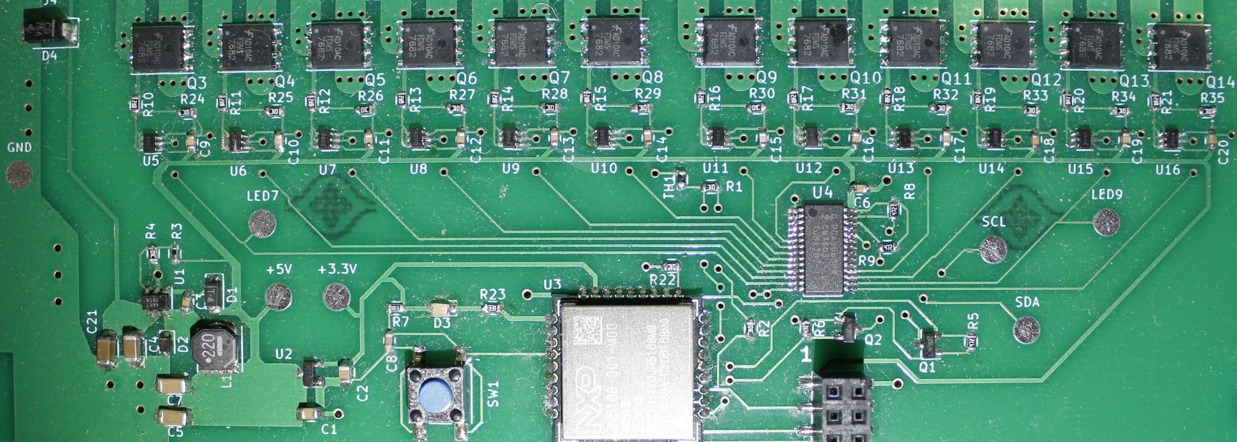
The mounted standard-variant board looks like this:
![]()
The boards don't have a high part density, so they can be soldered by hand, even if all you have is a budget soldering iron. But I would highly recommend using the skillet reflow method as it is easier, and all the parts are on one side anyway. Using a reflow method is also good because it ensures that the huge drain pads of the MOSFETs get (thermally and electrically) connected properly. -
4Installing the toolchain
Code for the JN5168 is compiled using BeyondStudio for NXP. You will also need to install BeyondStudio even if all you want to do is program the JN5168. Unfourtunately, BeyondStudio looks like it's a Windows-only program.
All programs and utilities are available for download from NXP's site here. You will need the following:
- JN-SW-4141 (BeyondStudio)
- JN-SW-4168 (ZLL SDK)
You'll probably need to create an account (this process should be free) to download the SDK.
(If you're viewing this from the future, and NXP has abandoned these tools, so they're not available for download, please contact me - I might be able to help you.)
- Install JN-SW-4141 as described in section 1.2.1 of JN-UG-3098.
- Install JN-SW-4168 as described in section 1.2.2 of JN-UG-3098.
- Install ZigBee plugins as described in section 1.2.3 of JN-UG-3098. When prompted to browse for the plugins' sub-folder (during Step 4 of section 1.2.3), browse to [BeyondStudio install location]/sdk/JN-SW-4168/Tools/Eclipse_plugins/com.nxp.sdk.update_site - note that the associated plugin name can be anything.
-
5Building the firmware
Pre-compiled binaries are available in the Files section of this project.
However, if you wish to compile from source, get the firmware sources from github, perhaps by using github's "Clone or download" button, or by running
git clone https://github.com/someone42/ZLL_Lights.gitPut the repository somewhere that isn't in BeyondStudio's install location or workspace. Next, open BeyondStudio (if prompted for a workspace location, just accept the default, but remember where it is) and import the project:
- Select "File"..."Import..."
- Expand the "General" tree (if it isn't already expanded)
- Select "Existing Projects into Workspace" and click "Next"
- Click "Browse..." and browse to where you put the repository
- Ensure "Search for nested projects" and "Copy projects into workspace" are ticked
- Click "Finish"
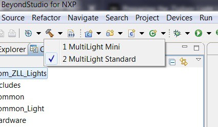
You may need to close the "Welcome" tab. There should be a "C/C++ Projects" tab which has the "Custom_ZLL_Lights" project. The project should be open, if it is not, double-click it to open it. Click on the drop-down arrow next to the Build icon (a hammer) and select your board variant:
![]()
If you wish to build firmware for both board variants, ensure you clean the project (click on the "Project" menu, then select "Clean...") before each build.The firmware binaries should appear in [workspace location]/Custom_ZLL_Lights/: MultiLight_JN5168_JN516X_RGBStandard.bin for the standard variant, and MultiLight_JN5168_JN516X_RGBMini.bin for the mini variant.
-
6Programming the boards
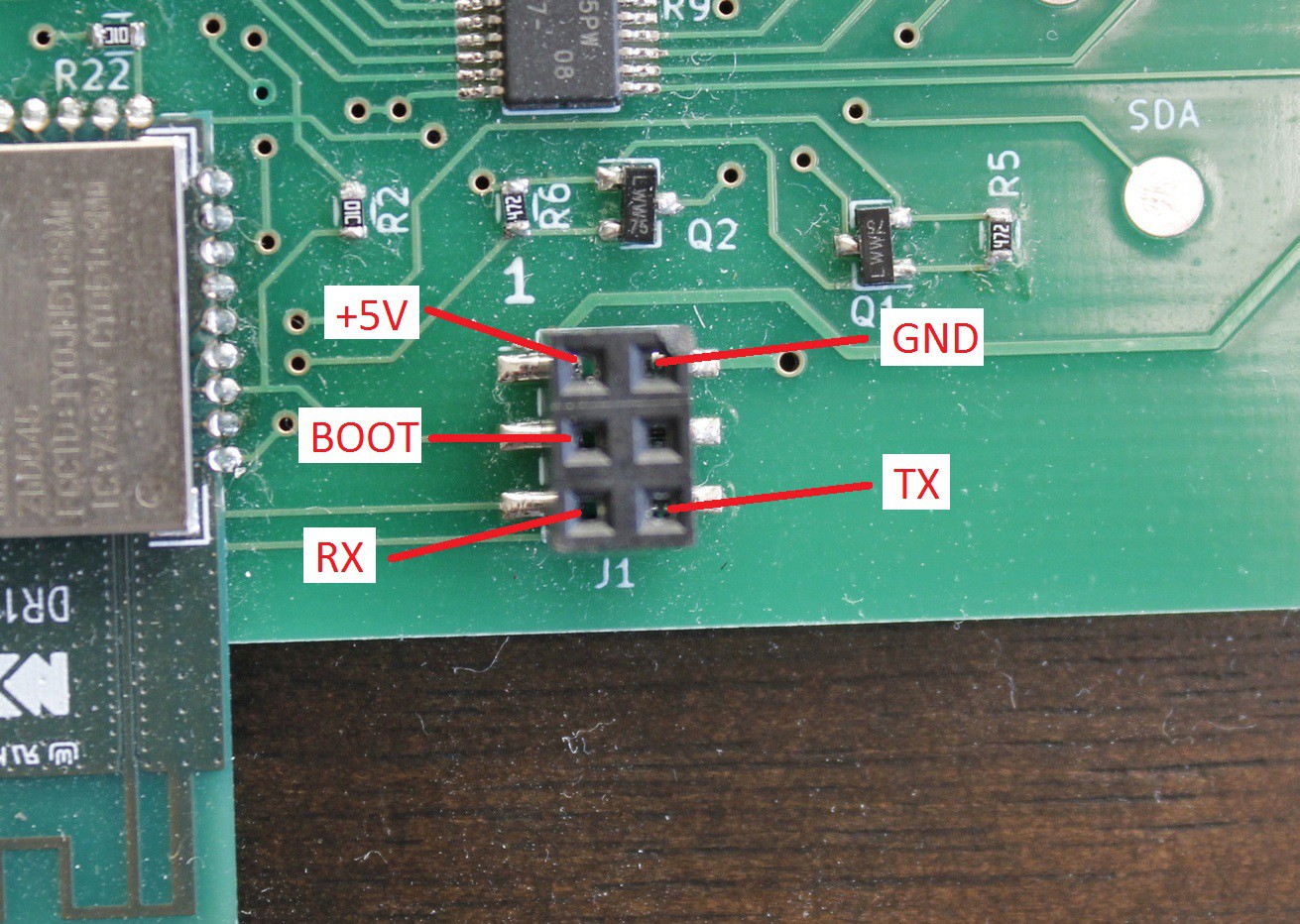
You will need some sort of USB-to-serial converted. During programming, do not externally power the board. Connect the USB-to-serial converter to the 6-pin programming header J1 as such:
![]()
For the purposes of programming, the "+5V" pin can be connected to either +5V or +3.3V. The "TX" and "RX" are TX/RX from the perspective of the USB-to-serial converter. If in doubt which way they're supposed to go, try one way, and if it doesn't work, try the other :-)
The "BOOT" pin selects whether the JN5168 enters bootloader mode or not. If BOOT is connected to GND, then the JN5168 will enter bootloader mode, if BOOT is left unconnected, the JN5168 will enter normal mode. For the purposes of programming the board BOOT should be connected to GND. After you have connected the USB-to-serial converter to the 6-pin programming header, press SW1 to reset the board, causing the JN5168 to enter bootloader more.
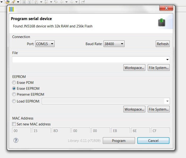
From within BeyondStudio, click the "Devices" menu and select "Program Device". Select the COM port of your USB-to-serial converter, and set the baud rate to 38400. Press "Refresh" and you should see something like:![]()
Note that the MAC Address is something reasonable (not all FFs). If you don't see this, or there is a "Failed to read chip details" error:- Check that the board is receiving power - there is a +3.3V test pad that you can use to check this
- Try swapping TX/RX around
- Check that the BOOT pin is low (i.e. connected to GND)
- Try resetting the board by pressing SW1
- Press Refresh to try connecting to the board again
Press either the top "Workspace..." or "File System..." (in the File panel), and browse to the firmware binary you generated in the previous step. Ensure that "Erase EEPROM" is selected, then click "Program". The programming process takes a few minutes.
-
7Adding lights to the Hue app
After programming the board successfully, disconnect the BOOT pin and reset the JN5168 by pressing SW1. The green status LED (reference D3) should turn on. The rest of the pins can remain connected. You might want to use a multimeter to check the the status LED is not toggling very quickly (this can happen if the JN5168 enters a bootloop).
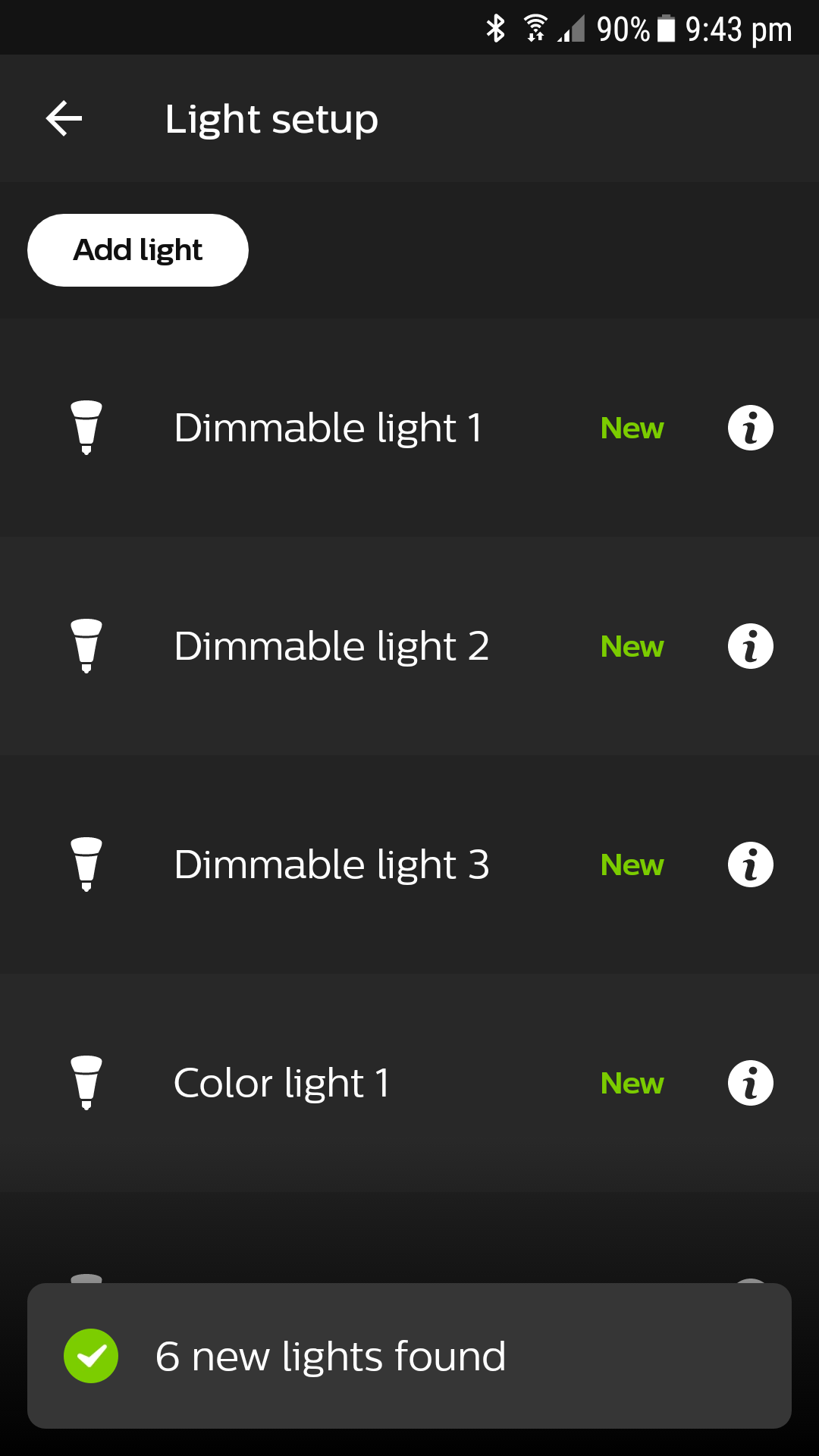
Open the Hue app, go to "Settings", "Light setup", press "Add light", then press "Search". Now reset the board by pressing SW1. The lights should appear (3 Dimmable and 3 Color for the standard variant, 1 Dimmable and 1 Color for the mini variant):
![]()
The lights can now be assigned to rooms and controlled from the Hue app. -
8Connecting power and LEDs
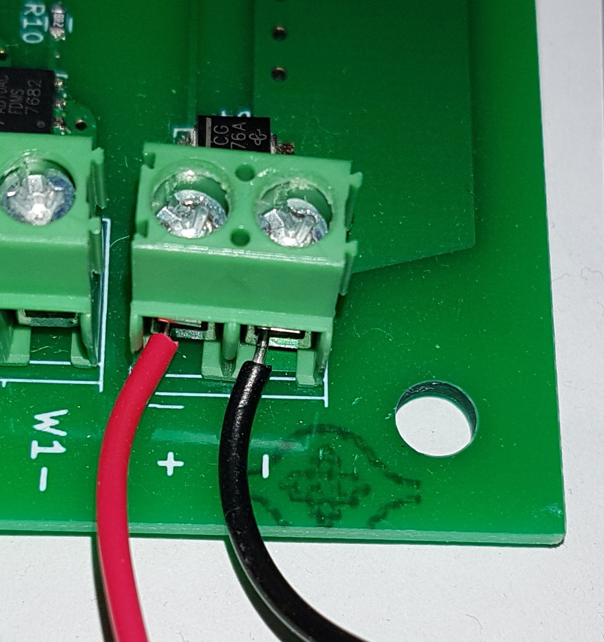
If there is still something connected to the 6-pin programming header (reference J1), disconnect it. Then you can power the board by connecting a power supply to the "+" and "-" terminals of the terminal block. The power supply can be anything from 5 V to 24 V, and the board itself only needs something like 20 mA.
![]()
Each LED channel has a pair of terminal connections, one labelled "-" and one labelled "K". To connect an LED:
- Connect the power supply positive to the LED's anode
- Connect the LED's cathode to the "K" terminal on the controller board
- Connect the power supply negative to the "-" terminal on the controller board
![]()
The MOSFETs are rated for a recommended maximum of 16 A, 24 V, and an absolute maximum of 22 A, 30 V. The controller board doesn't do any current control/limiting - that's assumed to be the responsibility of the power supply or the LEDs themselves (i.e. they should have an internal resistor). -
9Cooling
If the average current is less than 4 A per channel, you should be fine with no board cooling at all. For larger average currents, the board will need to be thermally connected to a heatsink or enclosure. The firmware does check the board's temperature, and will shut off all lights if board temperature exceeds 85 degrees Celsius. But you shouldn't rely on this! If the firmware hangs or bootloops, temperature checking won't be done.
The board is designed so that heat goes to the bottom side. The majority of the heat comes from the MOSFETs, so you only need thermal paste/adhesive on the highlighted area:
![]()
The MOSFETs have a worst-case ON resistance of about 0.010 ohm, so the approximate heat generated P is 12*I*I*0.01, where I is the average current per channel, in ampere. For example, if each channel was expected to switch 10 A, then you would need a heatsink capable of dissipating 12*10*10*0.01 = 12 W of heat. A fan is probably unnecessary, unless you are only able to use a small heatsink.
-
10Board configuration
To configure gamma, brightness, computed white mode etc., connect a USB-to-serial converter to the programming header, as in step 6. However, assuming the board is externally powered, do not connect anything to +5V and BOOT i.e. only TX, RX and GND should be connected this time. The board should be in normal mode i.e. the green status LED should be on.
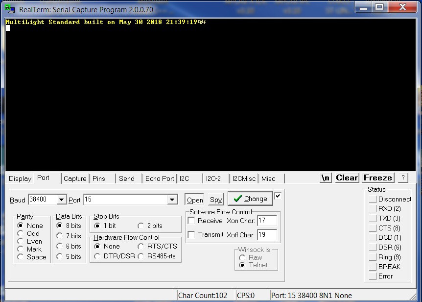
Using some serial terminal program, connect to the board at 38400 baud, mode 8N1. Issue a version command by sending v [CR] [LF] and the board should give you a version string:
![]()
For a list of commands, see this.
High-power ZigBee LED light controller
Hue-compatible LED light controller with 12 channels, each capable of controlling up to 384 W
 Chris Chua



Discussions
Become a Hackaday.io Member
Create an account to leave a comment. Already have an account? Log In.