MakersBox
-
Steppin the Steppers
06/18/2018 at 21:48 • 0 commentsI had a little bit of trouble of piece together enough information to get this running, so hopefully this will help others. The key document you need is at https://www.dfrobot.com/wiki/index.php/Stepper_Motor_Shield_For_Arduino(DRV8825)_SKU:DRI0023
Connect the stepper wires and power supply to your shield:
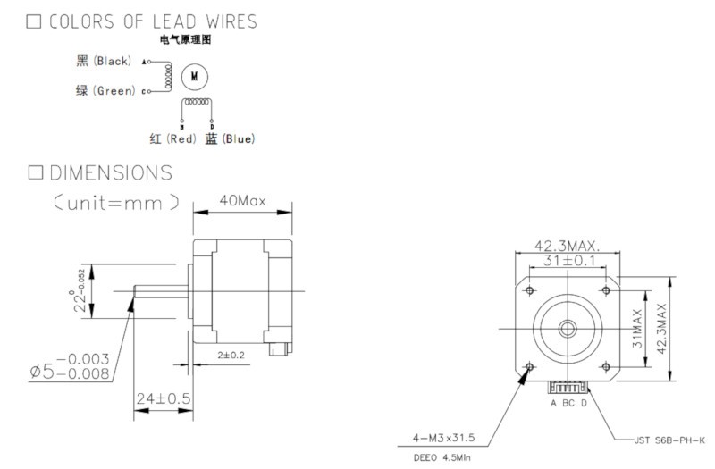
- 2B Blue
- 2A Red
- 1A Black
- 1B Grenn
The provided example sketch worked for me, but is not too instructive. We will need to control speed and rotation as well as release the stepper motors when not in use to save power.
I found an modified an example from http://bildr.org/2011/06/easydriver/ which has helper functions. It only drives one stepper at a time, but will give you confidence we are on the right track. We will write some more sophisticated code later.
////////////////////////////////////////////////////////////////// //©2011 bildr //Released under the MIT License – Please reuse change and share //Using the easy stepper with your arduino //use rotate and/or rotateDeg to controll stepper motor //speed is any number from .01 -> 1 with 1 being fastest – //Slower Speed == Stronger movement //http://bildr.org/2011/06/easydriver/ /* MS1 MS2 MS3 LOW LOW LOW FULL HI LOW LOW HALF LOW HI LOW QUARTER HI HI LOW EIGHT <---- HI HI HI SIXTEENTH 1/8 Step = 1600 steps per revolution FIT0278 Hybrid stepper 1.8 deg/step 2B Blue 2A Red 1A Black 1B Green */ ///////////////////////////////////////////////////////////////// // Drives M1 only, use DIR_PIN 4 and STEP_PIN 5 for M2 #define DIR_PIN 7 #define STEP_PIN 6 void setup() { pinMode(DIR_PIN, OUTPUT); pinMode(STEP_PIN, OUTPUT); } void loop(){ //rotate a specific number of degrees rotateDeg(360, 1); delay(1000); rotateDeg(-360, .1); //reverse delay(1000); //rotate a specific number of microsteps (8 microsteps per step) //a 200 step stepper would take 1600 micro steps for one full revolution rotate(1600, .5); delay(1000); rotate(-1600, .25); //reverse delay(1000); } void rotate(int steps, float speed){ //rotate a specific number of microsteps (8 microsteps per step) – (negitive for reverse movement) //speed is any number from .01 -> 1 with 1 being fastest – Slower is stronger int dir = (steps > 0)? HIGH:LOW; steps = abs(steps); digitalWrite(DIR_PIN, dir); float usDelay = (1/speed) * 70; for(int i=0; i < steps; i++){ digitalWrite(STEP_PIN, HIGH); delayMicroseconds(usDelay); digitalWrite(STEP_PIN, LOW); delayMicroseconds(usDelay); } } void rotateDeg(float deg, float speed){ //rotate a specific number of degrees (negitive for reverse movement) //speed is any number from .01 -> 1 with 1 being fastest – Slower is stronger int dir = (deg > 0)? HIGH:LOW; digitalWrite(DIR_PIN, dir); int steps = abs(deg)*(1/0.225); float usDelay = (1/speed) * 70; for(int i=0; i < steps; i++){ digitalWrite(STEP_PIN, HIGH); delayMicroseconds(usDelay); digitalWrite(STEP_PIN, LOW); delayMicroseconds(usDelay); } } -
Design Considerations
05/31/2018 at 22:16 • 0 commentsIf accuracy and precision are the goals, then most of the design decisions will rotate around the stepper motor (pun intended). The geared 28byj48 steppers (http://a.co/8bPbFhK) I've been using are incredibly cheap and work reasonably well, but they have both rotational errors from the backlash gears and axial errors from slop in the bearings. If you have ever watched a 3D printer or CNC milling machine do its thing, you know that those errors have been virtually eliminated. Most hobby grade machines use bipolar 2-phase stepper motors, so that is where we start. At about $15 each, our Turtle build is already at about half the budget of my normal robot, but hey, we are not counting costs on this one, right?
I'm going to be using the DFRobot hybrid stepper (https://www.dfrobot.com/product-785.html). I honestly don't know what the "hybrid" means. Perusing the data sheet, we know the following:
- It is heavy, so my normal light-weight chassis design is going to need some beefing up.
- It draws a lot of current, so 4 x AA batteries are not going to cut it.
- It has a 5 mm shaft, with a single flat surface so my current wheel design will need rework.

Here are my starting thoughts on design:
- Size the chassis based on having the steppers butting up against the pen/servo assembly to stiffen the chassis. Hopefully we can keep it within 150 mm square so I can still 3D print it on my printer.
- Use "C" sized batteries, which will provide a significant increase in capacity. The stepper shield specifies 8 - 35V, so I'm thinking 6 cells x 1.5 = 9V. Those plus the steppers are going to represent most of the weight of the unit.
- DFRobot has a large wheel that looked good, but was out of stock. It does uses an interesting coupling that I think I can design a 3D printed wheel around to provide something robust.
First things first, we need to get our hands on the hardware and learn to make the steppers move . . .