 BaiLiping
resources:
1. https://dberard.com/
2. https://www.youtube.com/playlist?list=PL3592A61EEF52B29A
Cheap Scanning Tunneling Microscope
Already have an account? Log in.
To make the experience fit your profile, pick a username and tell us what interests you.
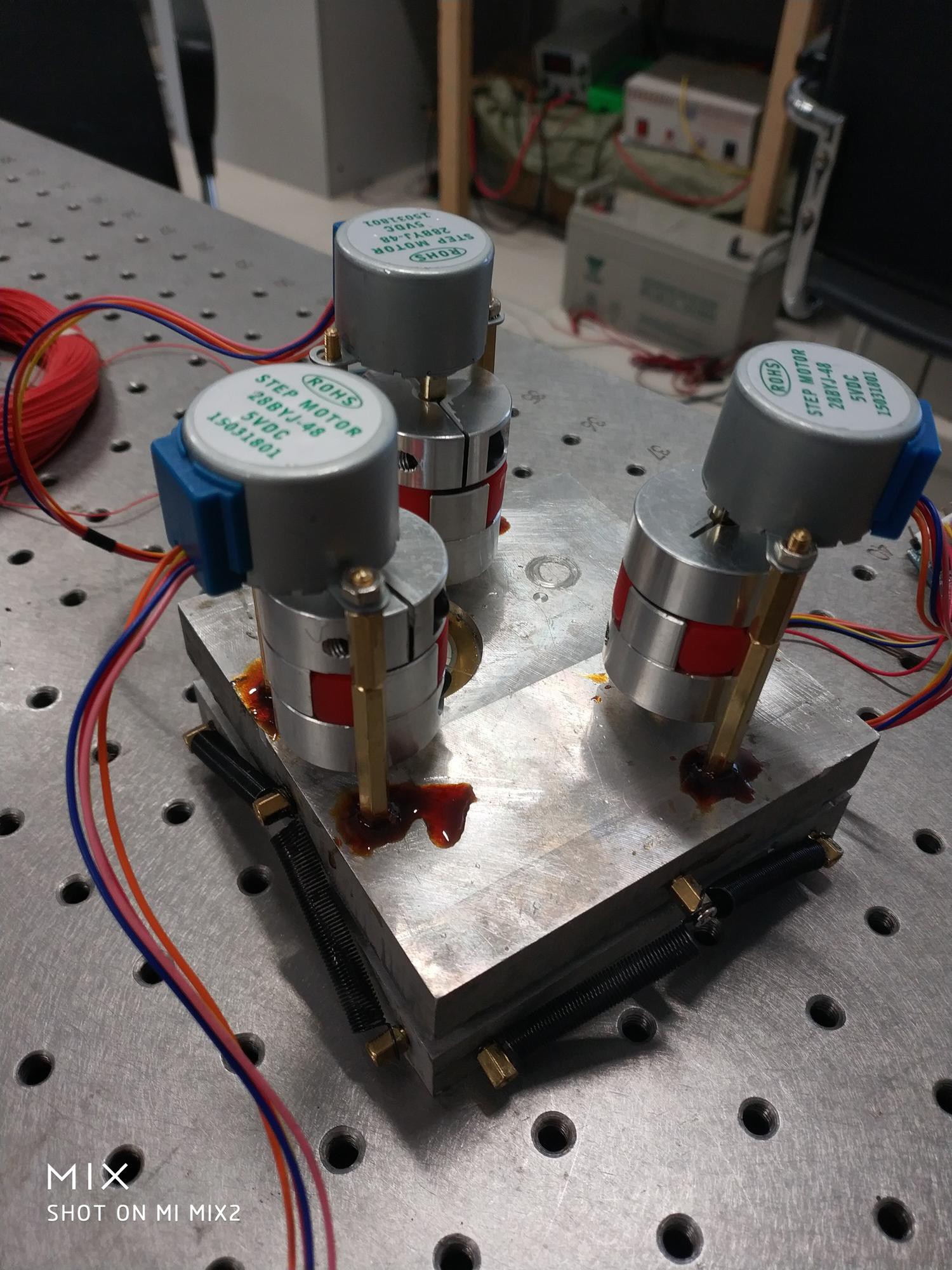
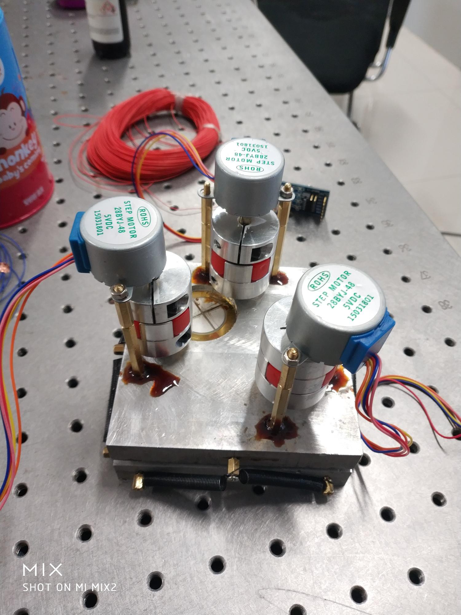
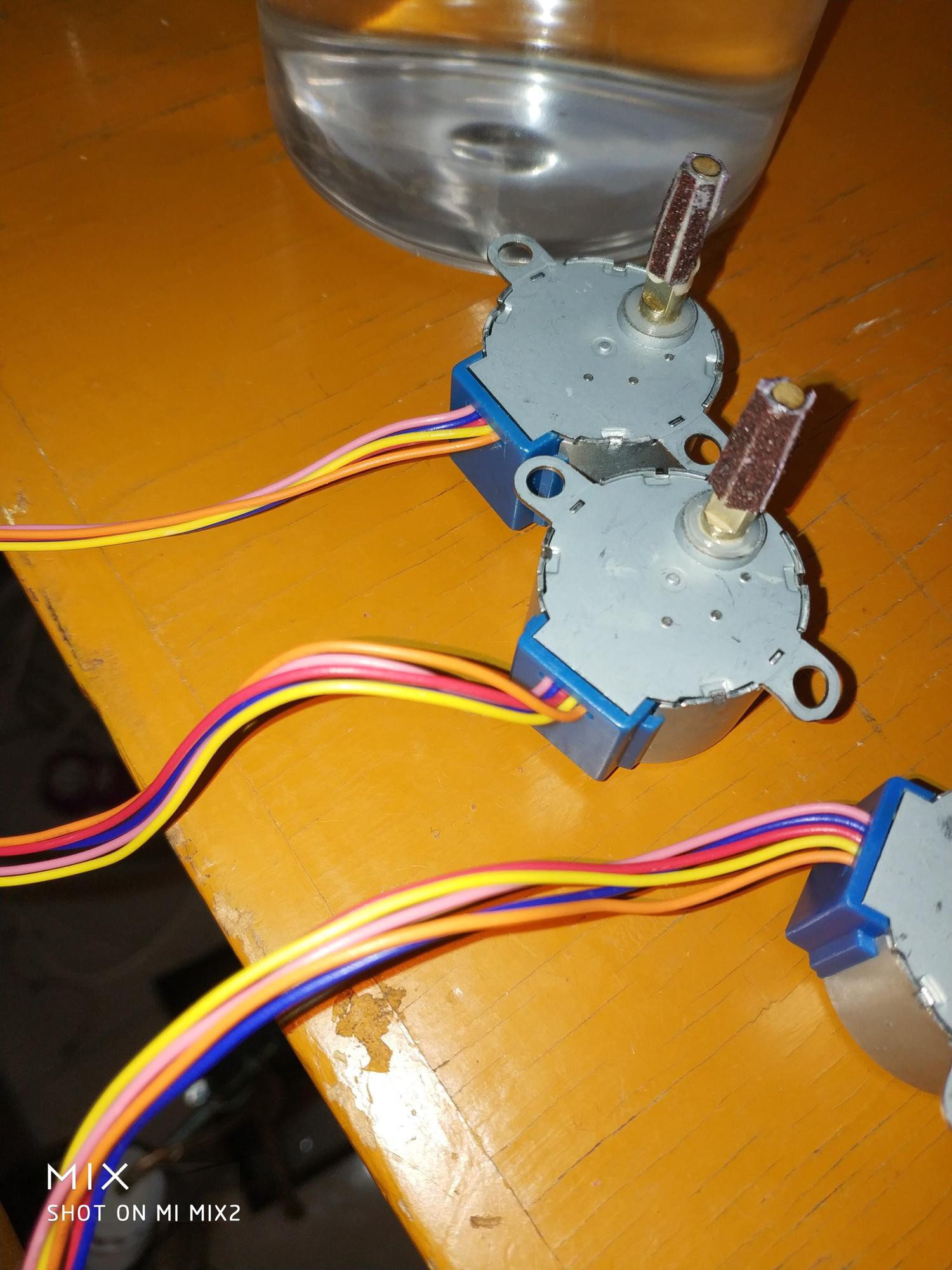
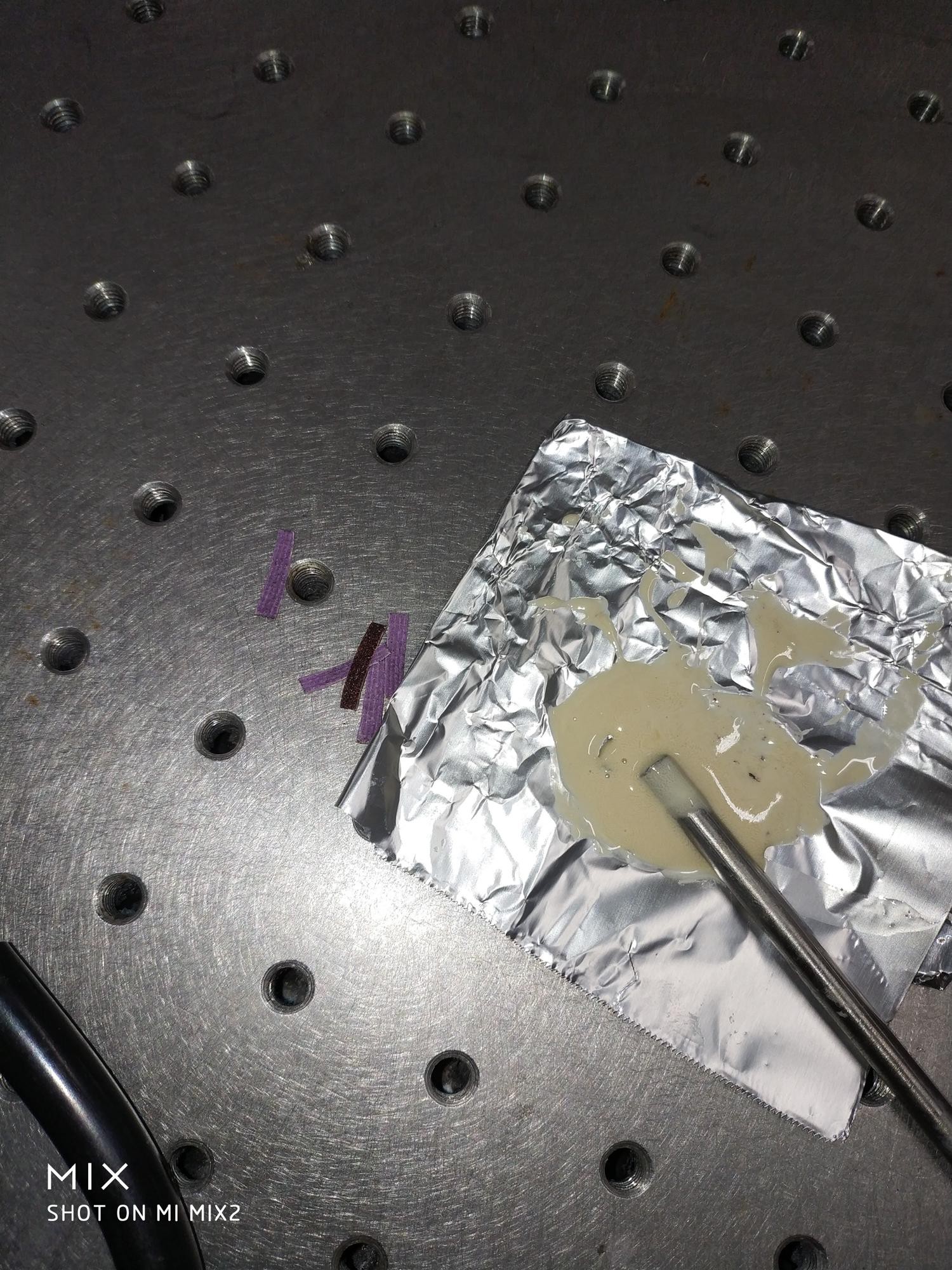
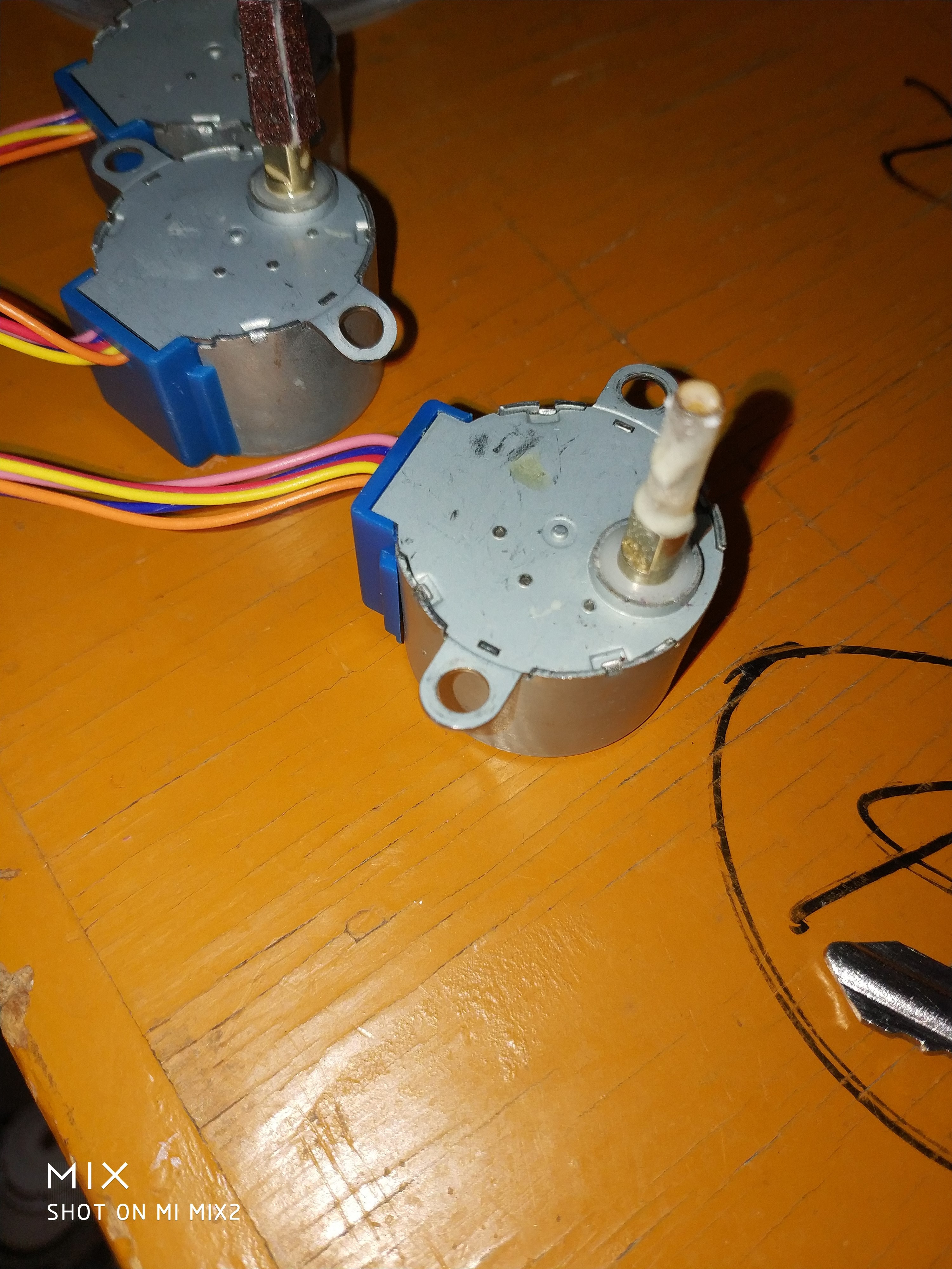
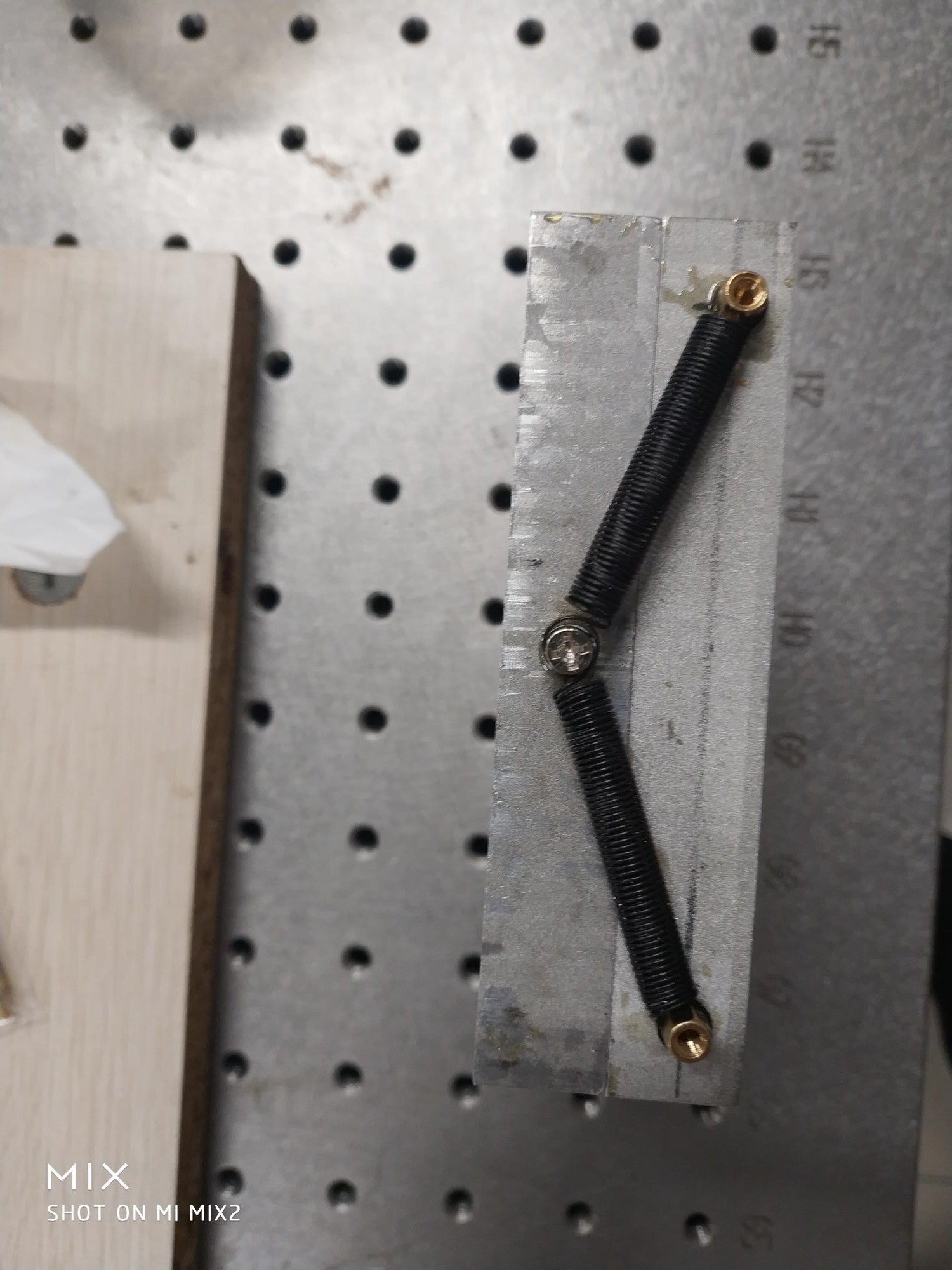
To increase the friction of the stepper and the connector, I added a 4mm diameter acrylic cylinder extension to the stepper, then wrapped that acrylic cylinder with coarse sandpaper. Coarse sand paper are not easy to bend, therefore, I cut them into small slices and glue them to the cylinder.
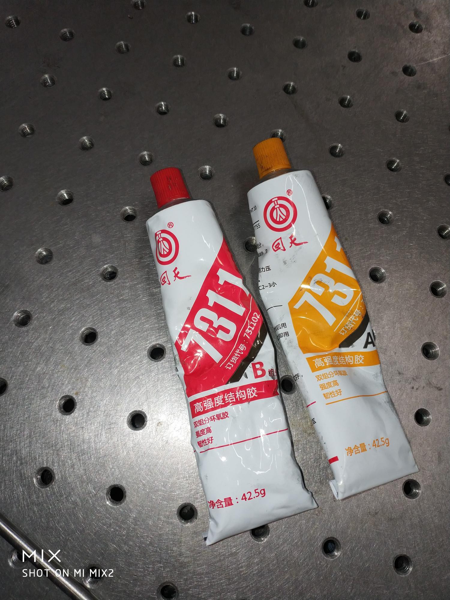
Also a good structural glue is quite handy in projects like this. Try to find ones that would cure at room temperature within 72h.
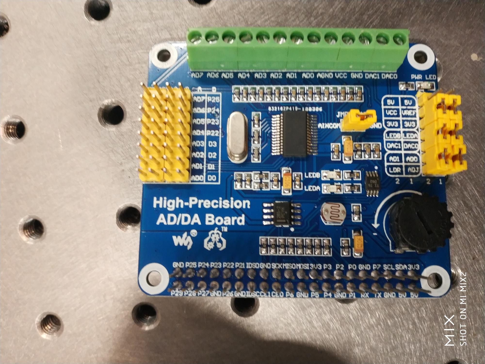
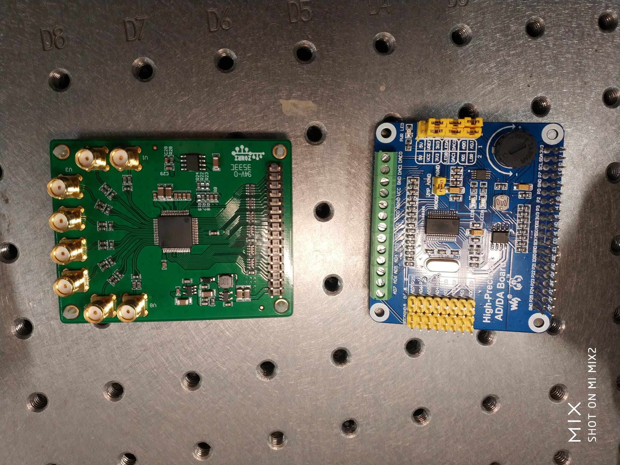
The higher resolution the better for ADC right? Actually, it is not quite so simple. There are information I hope to have possessed before the purchase of ADS1256, which is a 24-bit ADC.
1. While 24-bit ADC can give you a good signal to noise ration,other part of your circuit, such as the op-amp rarely keep up with that level of performance. Eventually, the signal to noise ratio is determined by the noisiest part of your circuit.
2. Using 24-bit ADC require some serious know-how, since at that resolution, your PCB board itself is part of your circuit. There are tons of tricks you need to do in order to fully take advantage of that 24-bit revolution. Even for the ultimate power user, the last 4 digits of a 24-bit ADC is mostly just noise.
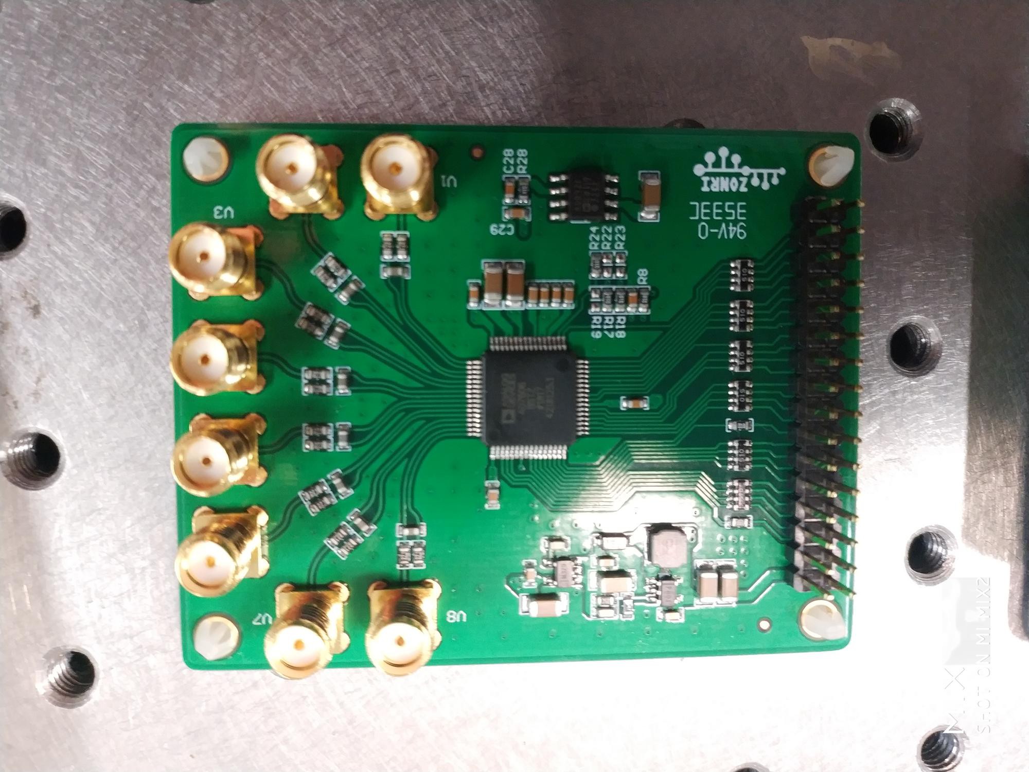
I might still give that ADS1256 a try. But one of my supplier offered AD7607 on sale, and it has a coaxial breakout, so I just went ahead and bought it. AD7607 is a 16-bit ADC, should be more than enough for our purpose.
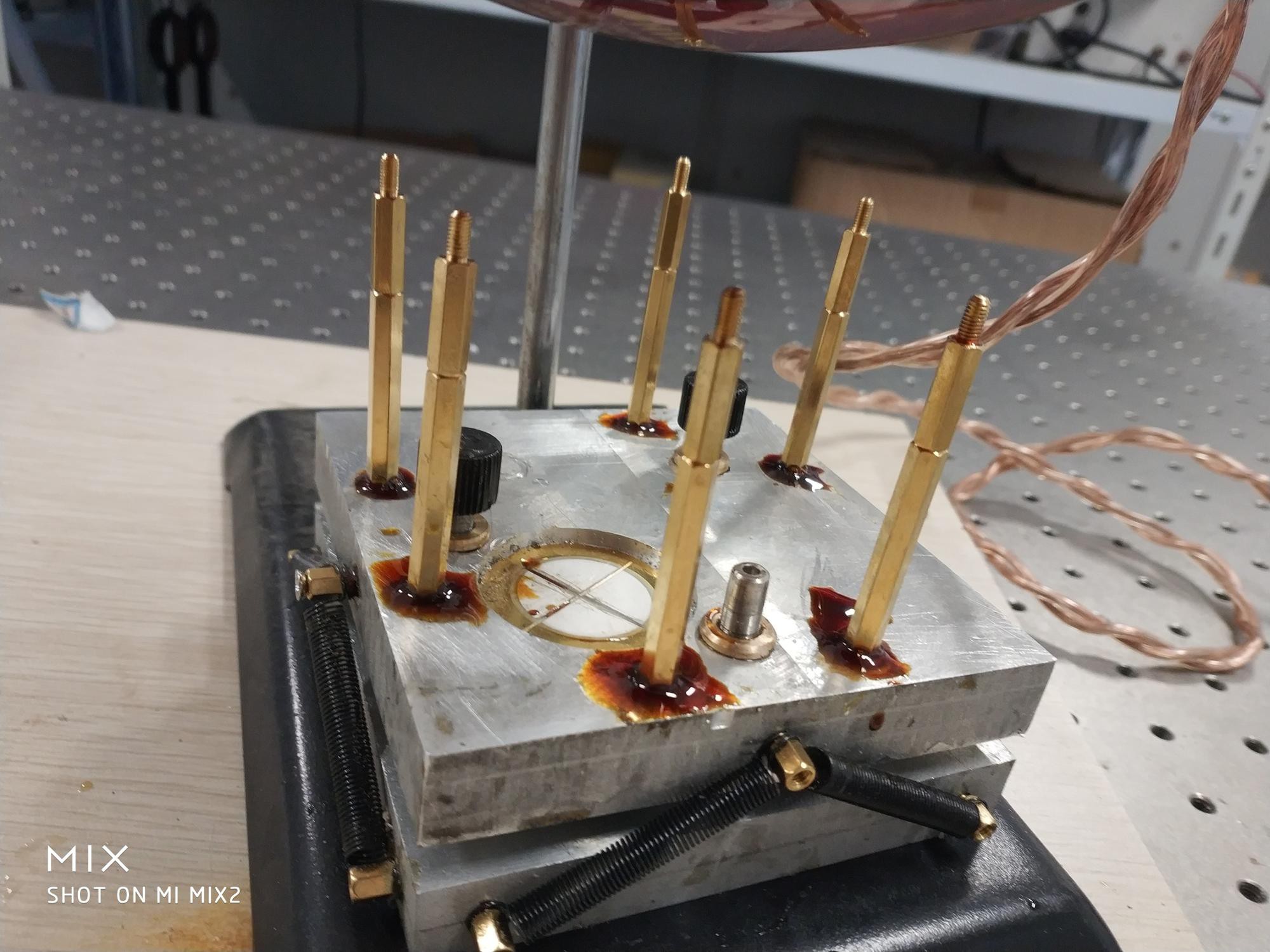
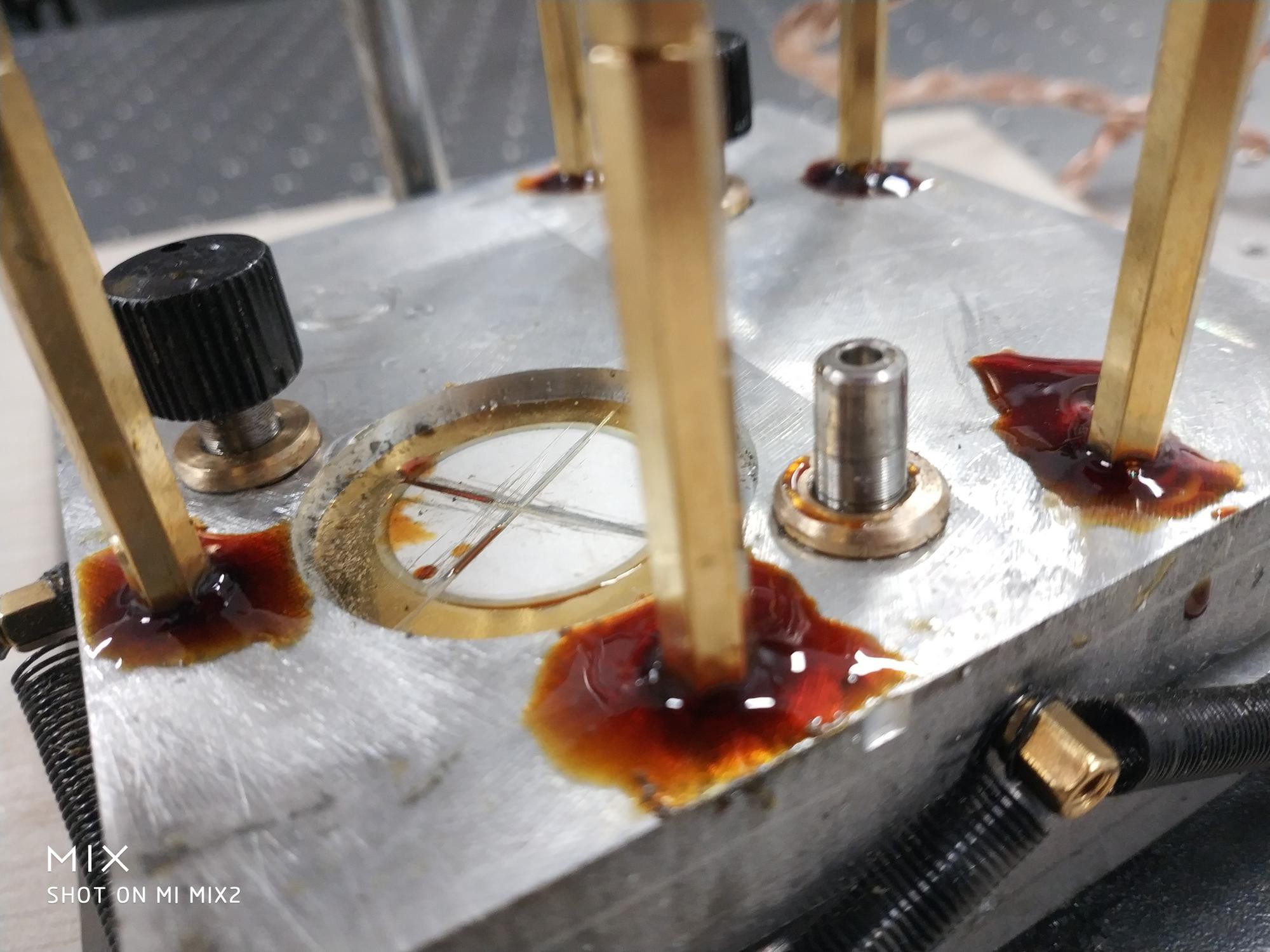
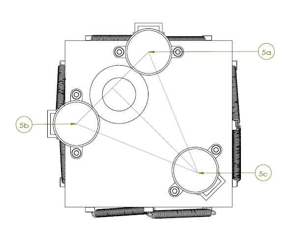
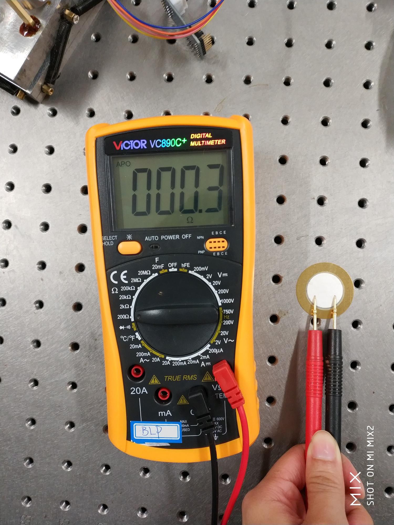
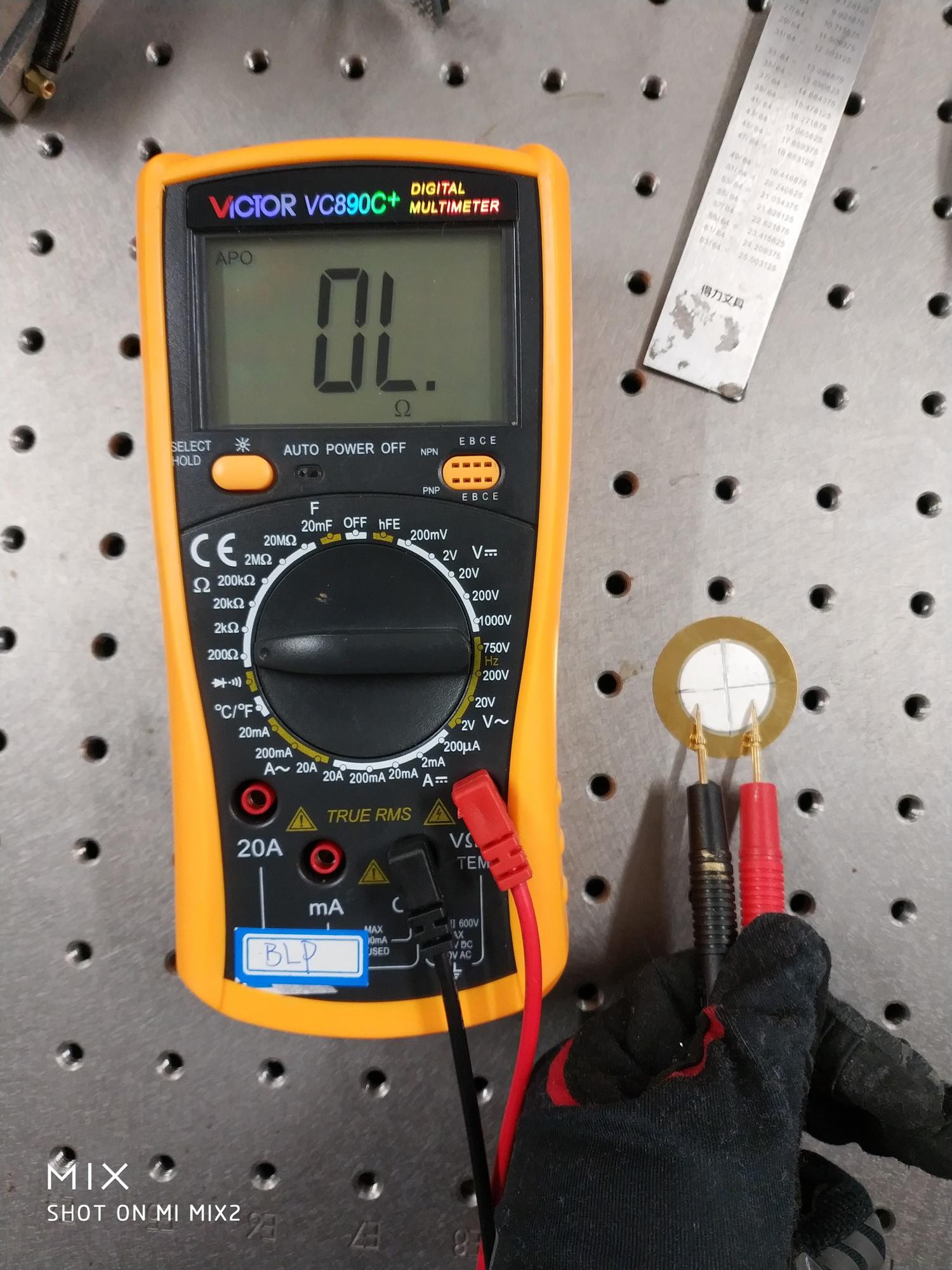
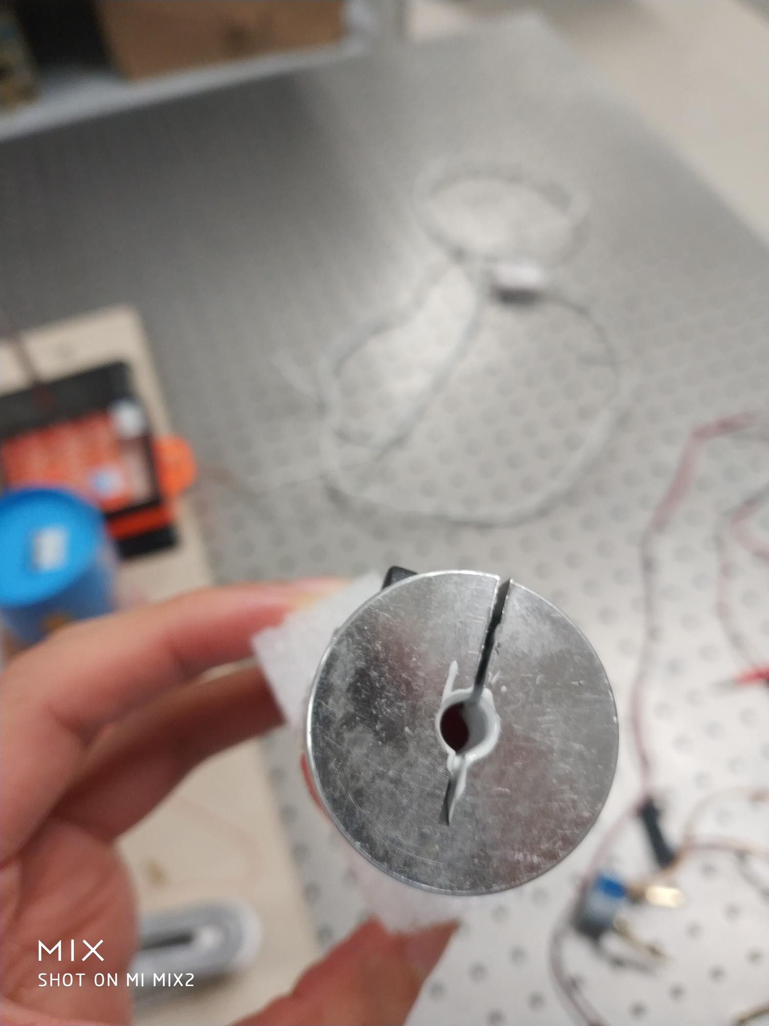
Originally I cut my peizo throughout. But andrei101 recommended only cut the top conducting layer such that the integraty of peizo crystal is preserved to the largest extend. So I look into that option.
Without cut, the conducting layer has a resistance of 0.3, but with just a thin cut, it is open circuit.
This serves our purpose perfectly. When a voltage is applied, only that particular region of peizo is engaged for the scanning movement. And with such a thin cut, the peizo remain in almost perfect conditions, without the minor cracks that inevitably develop during the deep cut process.
Thank you andrew101!! I owe you one.
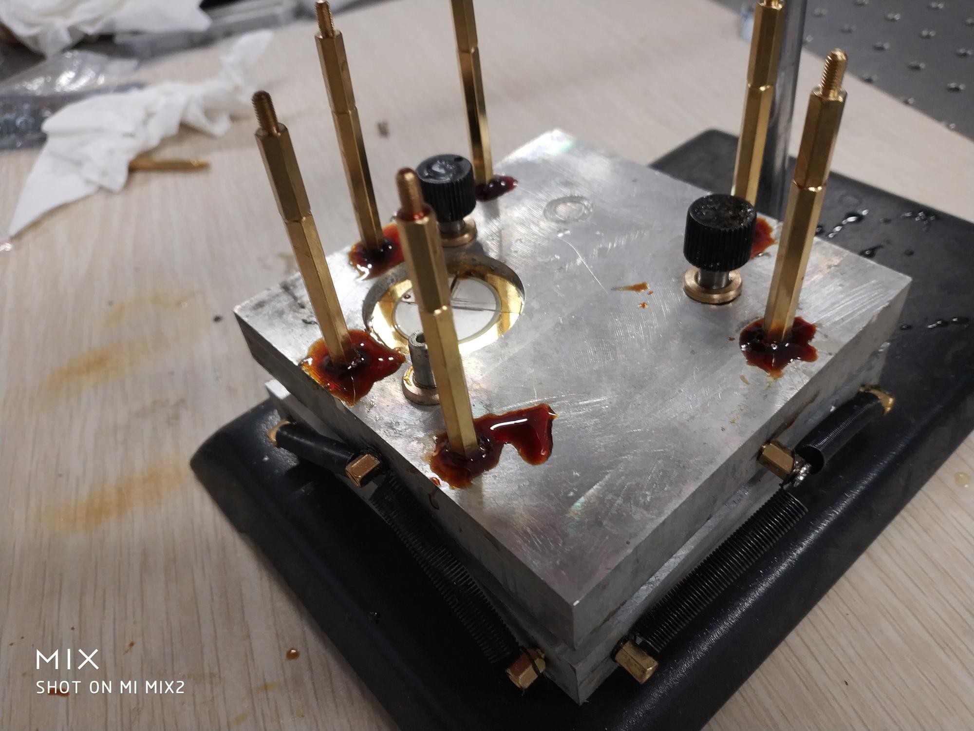
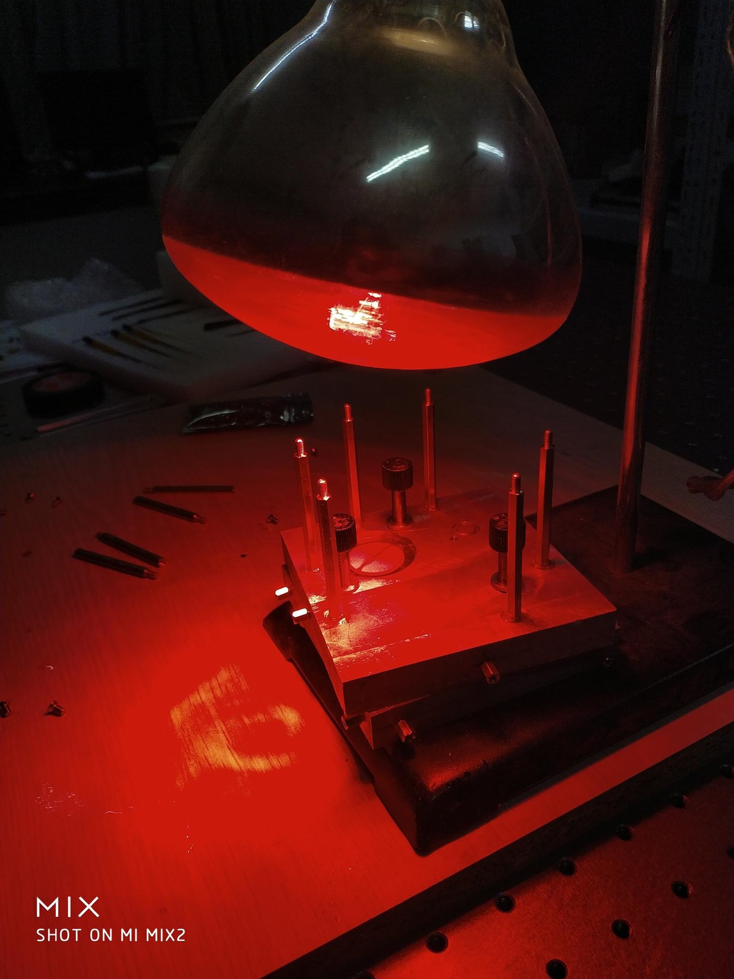
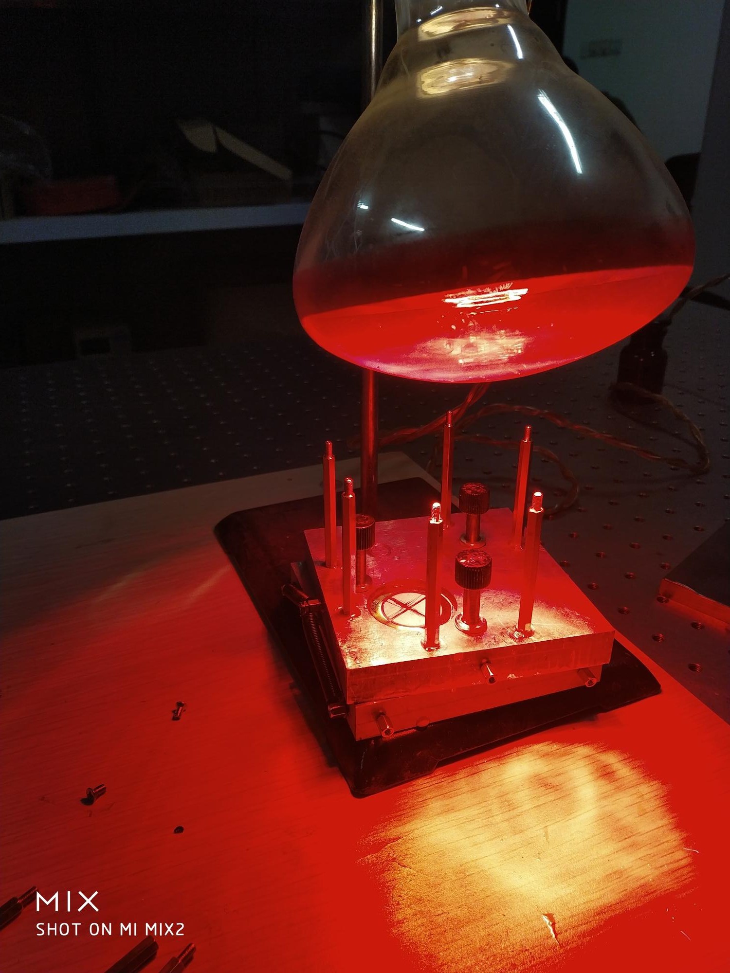
Supposedly, I should be able to screw everything together, but since the CNC shop can't make that M3 threaded hole, i'll just glue everything together. No biggie. However:
DO NOT STARE AT THE HEAT LAMP!!! this is from my own bloody experience. Just do not stare at that thing.
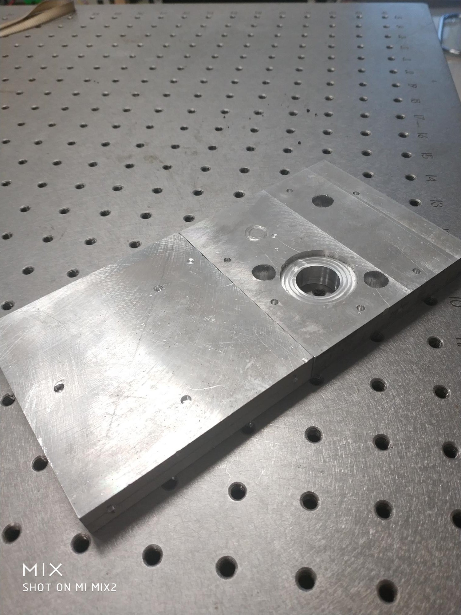
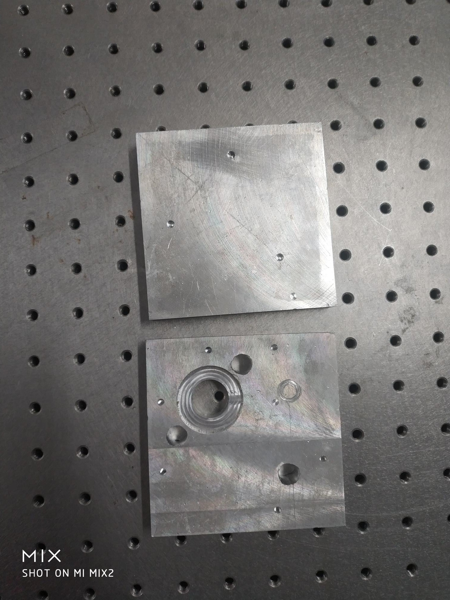
Today I went to the University CNC shop to get the aluminum block processed. Unfortunately, this being a university shop, people who are in charge of the place has a master in Mechanical Engineering, yet, new comer when it comes to CNC stuff. We ended up spend quite a lot of time for just the most basic drilling action.
University shop is mostly concerned with teaching 18 year old that such a thing exist, therefore, they don't have the whole set of tools. For instance, that M3 threaded hole should be the most common thing there is, yet we can't find the drill for that one. So I just decided to drill any kind of hole and then glue stuff to the aluminum using that high temp cured epoxy.
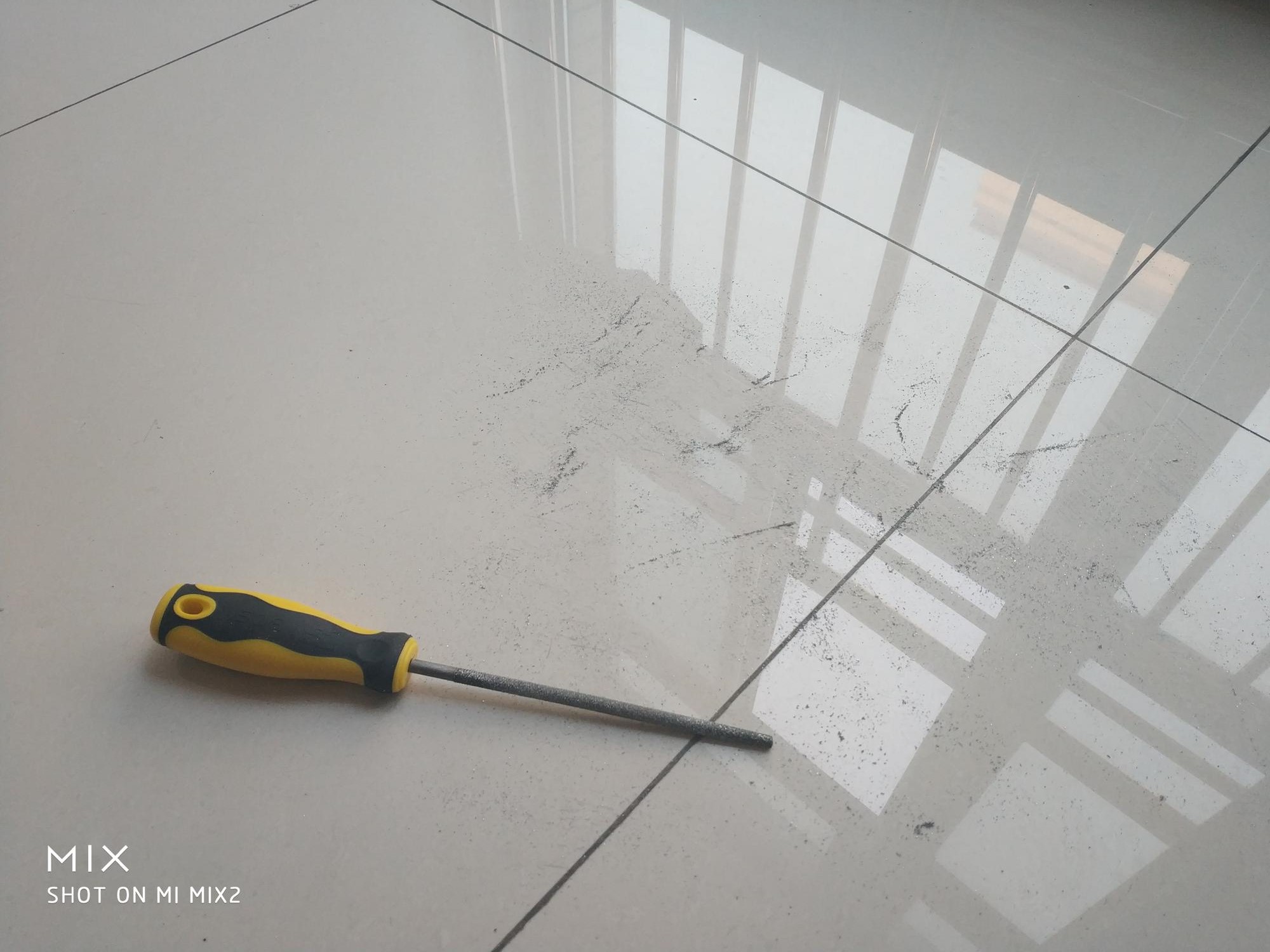
Also, the screw set has a diameter of 9.6mm which has to be exact for this design to work. YET I GOT A HOLE THAT IS 9.4mm!!! Initially, he tried to hammer it in, but that damaged the screw set such that it no longer turns around. So we force it out, and decided to manually increase the hole. USING A FILE!!! MANUALLY!!!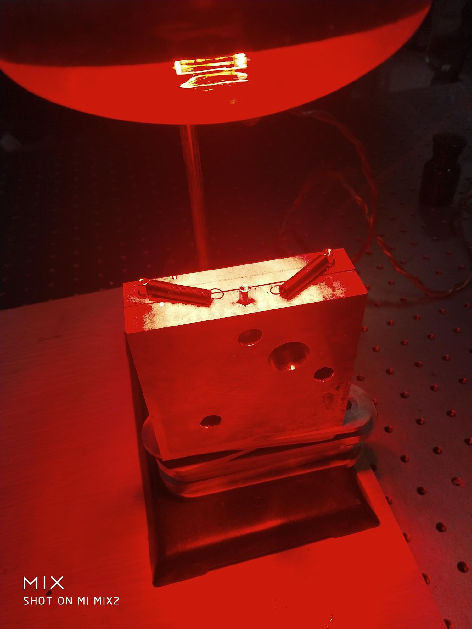
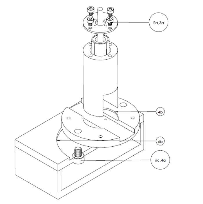
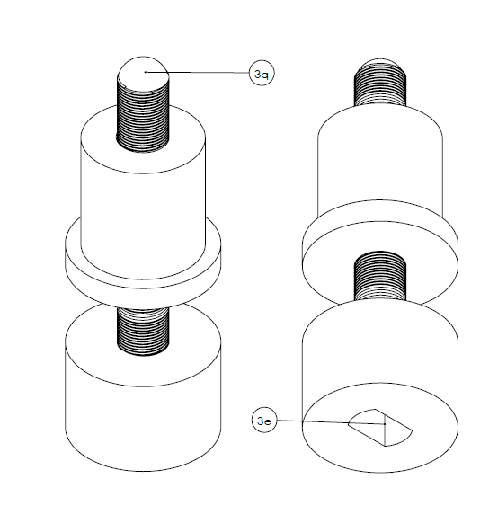
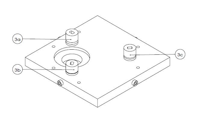
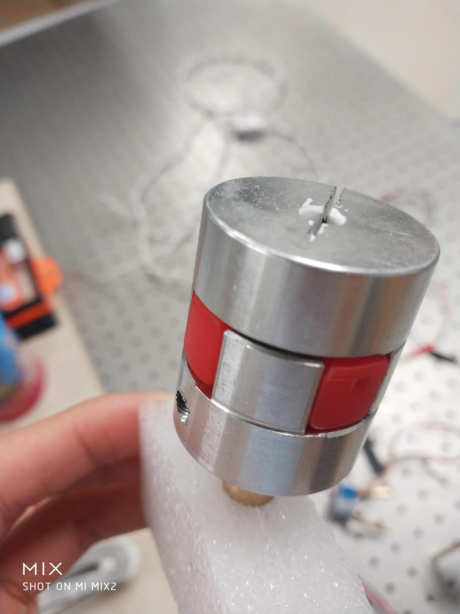
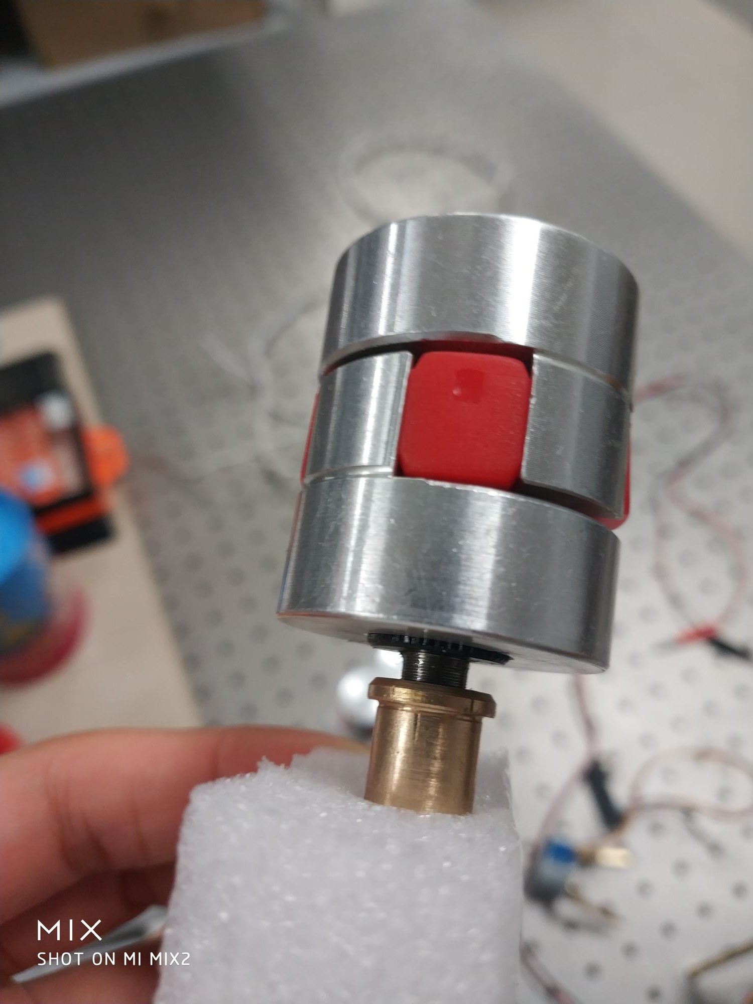
Turns out, Epoxy is a lousy structural glue. It can't hold up the force. Another issue is the original gliding design for the stepper z-axis movement did not work out. Therefore, change of plan. I find a supplier which manufacturing customized connectors. So I ordered one with 15mm hole on the one end and 5mm hole on the other. It is made of Aluminum, but I am still a bit worried if the steppers are strong enough to move all of those. So I added a thin layer of silica on the 5mm hole to increase the friction.
Peizo can be delicate. I find that the soldering point of the peizo stick would be the most finicky part. That is why I opted for the sticky copper wire instead of soldering iron. It is still prudent to check the integrity of your peizo after the cutting and wiring. I find 440Hz is effective frequency for this purpose. After the cutting and putting a copper part underneath the peizo disk, any movement generated by the peizo would be reduced greatly. If we apply 20V to the peizo, too low of a frequency, you can't hear a thing, too high of a frequency, it would generate nasty sound and damage your ear. 440Hz, the central C is best.


I would say the best benefit of being a Chinese these days is the access to all kinds of raw materials. It is a good time to be a hobbyist. I would love to try out the acid etching method you recommended. I did not know that you can itch out PZT. Will look into that option. Thank you for the recommendation.
Yeah Im definitely jealous! You don't actually need to etch out the PZT, its actually best if you don't damage the crystal. so you just need to remove a cross in the silver coating on the top side.
looks good! also for the electronics: I spent a long time choosing which adc / dac I needed and it was almost all for nothing. Any low noise 16-bit DAC should be good, and I ended up using 10-15 steps per pixel to get sub-atomic resolution.
for the ADC I initially used the 12-bit one built into my micro controller and averaged 50 samples, then switched to the ads1256 in the fastest sample rate possible and it made no difference.
hope this helps

Never seen those ratcheting piezo motors before. Now I'm going to be thinking of all sorts of uses for them!
 brashtim
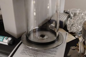
 rbalsan1
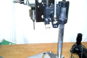
 Eric Hertz
 Wudagem
I can't believe you found those screws so cheap. I made one of these for £100 and the screws came to half of the total cost!! can recommend that you use acid to etch out your top layer pattern instead of scratching it