 Tim Wilkinson
Time to work out the actual inverse kinematics for the arm. The skeleton design for the arm looks like this:
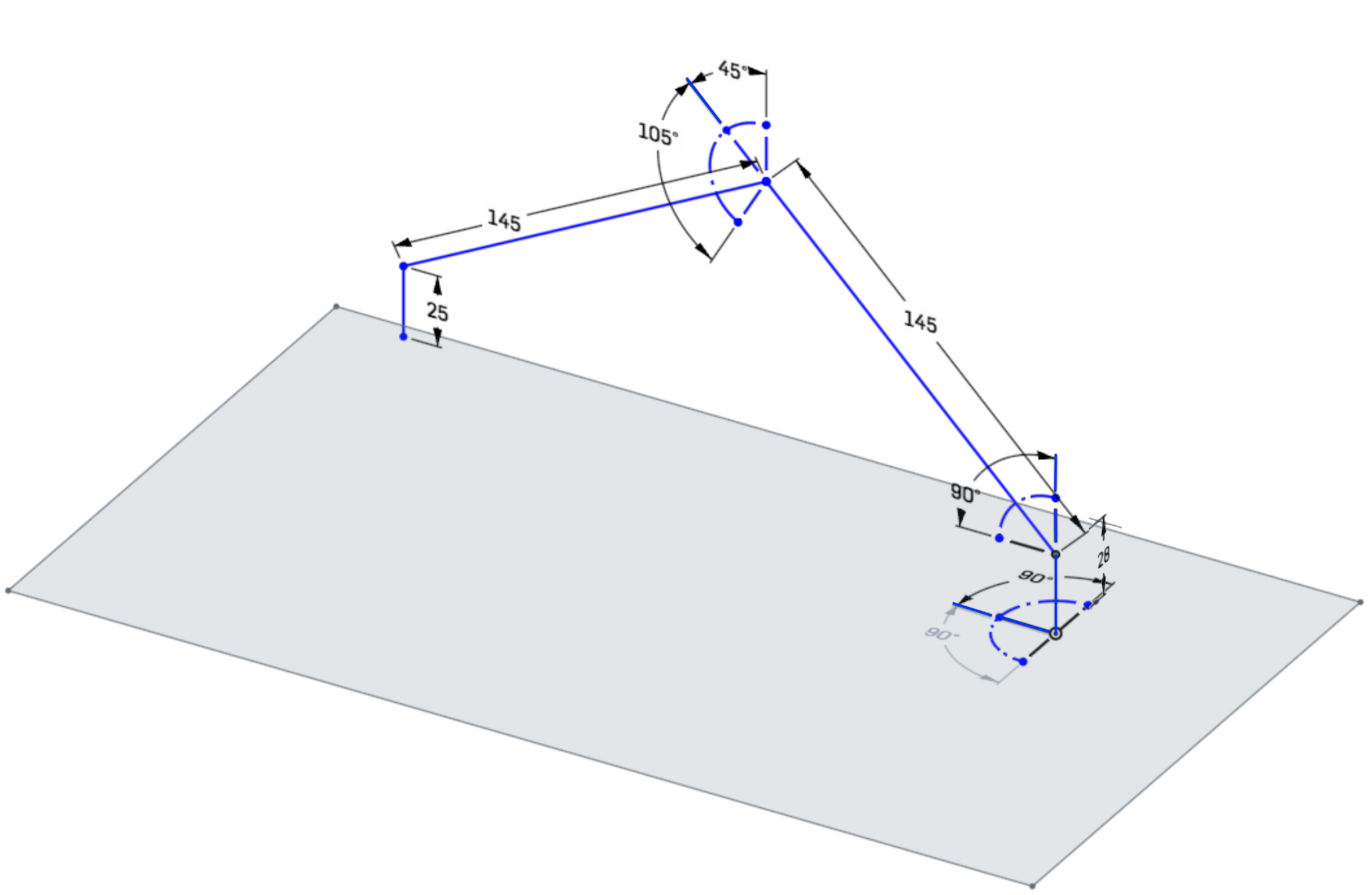
The arm is made of four bones and four hinges. The bone and hinge on the farthest left cannot be rotated independently; the arm was designed so this will rotate as the arm moves to keep the bone pointing directly down. This leaves three bones and hinges we need to model.
Using the 8BitModule visual editor, the arm IK looks as follows:
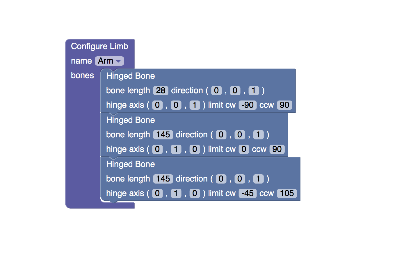
Here we have three bones with their given lengths (in mm, although units don't matter as long as they're all the same). The first hinge rotates around the z-axis, the remaining two around their relative y-axes. The relative direction of each bone is along the +ve z-axis (the arm is a straight line).
With this IK configuration we can now set the end of the arm (the effector) to the desired location and read back the generated angles for the hinges.
Discussions
Become a Hackaday.io Member
Create an account to leave a comment. Already have an account? Log In.
The parameters I'm using are basically those required by the underlying IK library. That said, I will now go off and attempt to learn what Denavit–Hartenberg is.
Are you sure? yes | no
Have thought about encoding this as Denavit–Hartenberg parameters?
Are you sure? yes | no