AVR
AVR-
Energy Harvesting Challenge 2018:
07/16/2018 at 13:38 • 0 commentsIn todays modern world there are many energy sources and storage methods available. The most design and powerful storage technologies are very expensive and controlled by patents. While there are many options for battery packs available there are not many open source solutions that have the same level of performance as the leading commercial solutions. SolPak is an attempt to build a open source battery pack that competes with the technology inside Tesla battery packs both home and car. There are many DIY powerwall and home battery storage projects online but SolPak will be using a custom BMS systemed based on the Tesla Model 3 battery pack.
SolPak addresses the energy harvesting problem from the storage side of things. There are many ways to generate electrical power, such as wind, solar, combustion, nuclear, and tidal. SolPak is none of those things though SolPak could hold the power generate by any one of them but I am choosing to focus on solar and mains voltage. Solar panels have come down in cost and have become more accessible, there are even ways to make DIY low cost panels, they also work off the grid in remote locations. Mains voltage is something available to most individuals on powergrids with homes, its always on and always available.
My focus with SolPak is to harvest energy from these sources for emergency use or remote use, a lot like the Tesla powerwall only free as in freedom. SolPaks can be deployed in the home to harvest AC power to keep the pack fully charged at all times until it is needed, either to power the home or something where mains voltage cant be found. The SolPak in solar applications will connect to a solar array to charge the pack. The pack will have a basic MPPT charge controller integrated into it but external panels will need to be bused together. This will allow users to use the pack with various solar arrays in different locations with easy and minimal external hardware.
Stay tuned and Lets Go!!!!
-
Progress with Case design and Electrical Systems
07/16/2018 at 03:24 • 0 commentsHey folks got some more updates for you this evening! So today I did a little bit more with the mechanical design realizing that I might want to change how things are arranged. This post is going to cover a lot, I want to talk about my proposed changes to the case and the BMS board progress.
So with the mechanical case, yesterday I talked about carbon fiber sheet and 2020 aluminum extrusion construction with sheet metal plates for wiring cells together. I still want to go that route but I want to make the battery stack its own mechanical structure out of carbon fiber sheets and integrate cooling piping/ribbon within it all as a module. This battery stack module would fit into the 2020/Cabron fiber sheet case along with all the other components of the system bolted in neatly together. I want to use 2020 aluminum for the main case and keep the internal submodules as carbon fiber sheet with tabs style boxes, this is to keep weight down. I played around in the CAD model I was working on to come to this realization. I started adding in extrusion to see how my original design concept would look and I just didn't like the idea of it hence the change of heart.
Here is where I am with the design before changing my mind:
![]()
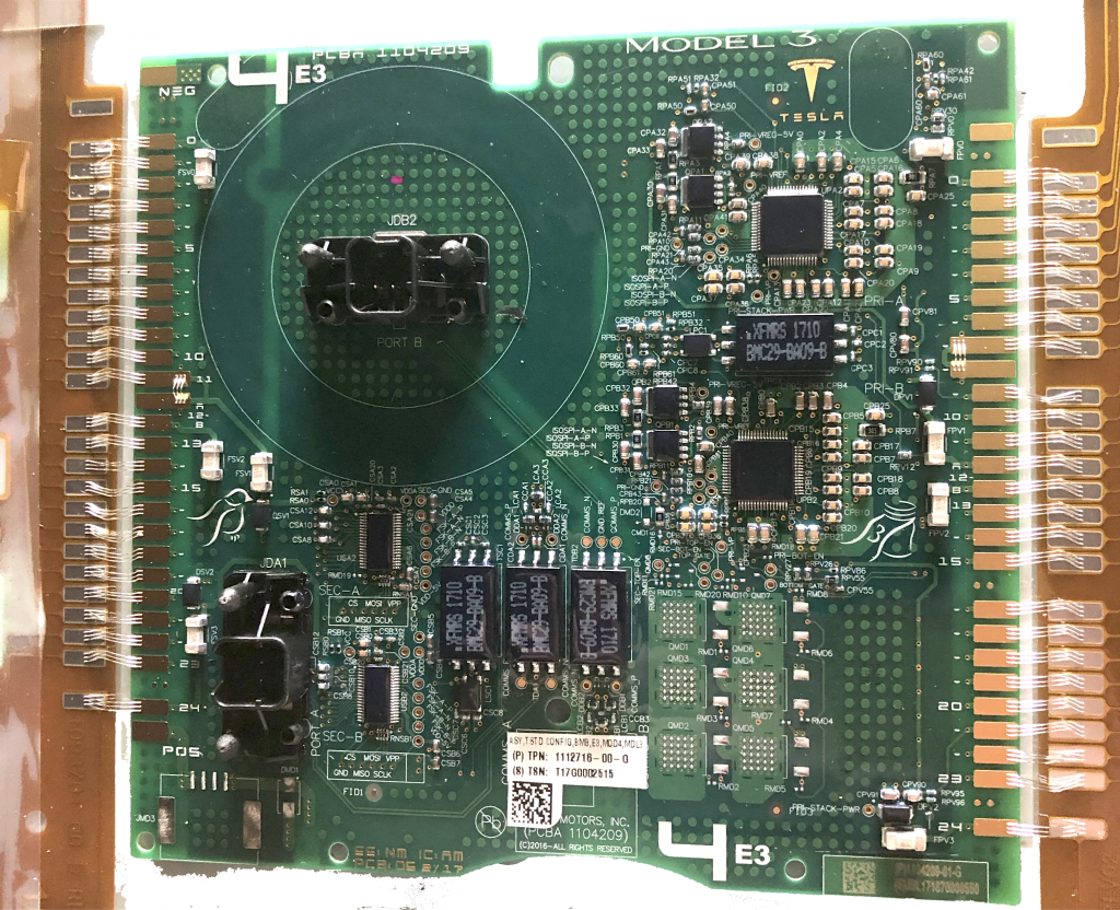
Now onto the electrical system. Even at this point I am still learning and wrapping my head around the technology and way its organized within the Model 3 battery. Jack Rickard really is right when he says its the best and most advanced battery out there, there is a lot going on. I watched his teardown video again, scoured the article, as well as looking through all the official ADI documentation. Through my searches I found all the documents relating to the evaluation kit for the LTC6813-1 from ADI, the chip that Jack suspects is the chip on board the Tesla Model 3 BMS board. My board aims to be a direct clone. From my visual inspection of Tesla's Model 3 board and looking at the layout/schematic from ADI's evaluation kit I also have strong suspicions that they are usign that chip and that the Tesla board is just a slightly modified and customized version of the evaluation kit.
The Tesla Model 3 BMS board:
![]()
Courtesy of EVTV, original image found here http://evtv.me/2018/05/tesla-model-3-gone-battshit/
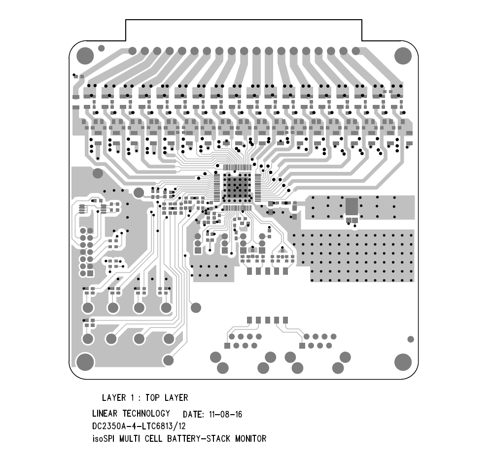
ADI Evaluation Board
![]()
If you know me really well you'll know that I eat, sleep, breath, think, worship, and life printed circuit boards. I tend to learn more about the circuit looking at the physical tracks and components on the board. While the images dont convey a 1:1 copy, alot of the supporting circuitry seems suspiciously in the same configuration, though I could be wrong since a lot of BMS systems will be similar but these main ICs habe 64 pins and they interface over that special ISO SPI interface. ISO SPI is just SPI serialized as a single differential pair, just some highspeed IC magic. It also looks like theirs 18 circuits for each "cell" that the chip can monitor, I come to this assumption by counting the caps around the chip, you'll notice they are all part of the same mini subcircuits. A circuit per battery cell. This is all speculation at the moment until I can get my hands on some ADI evaluation hardware and battery cells, moving on..........................
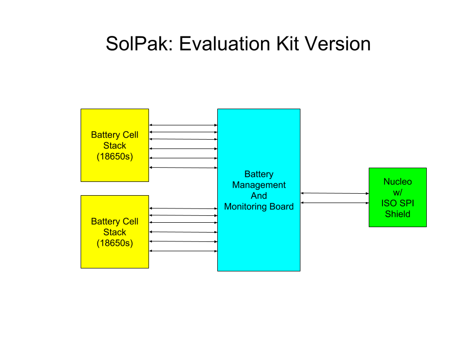
While designing my custom BMS board for this pack I'd like to evaluate the actual hardware from ADI. So my plan will be to do a pilot build of the pack using no custom electronics or if any they will be simple PCBs. This pilot build would also be small scale, it would be just enough cells for 1 chip and thats it. I'd build a small battery pack from 18650 cells, wire it to the BMS evaluation kit with a custom flexPCB for wiring the cells. For control I plan to make small shielf for the STM32 Nucleo baord that has the ISO SPI chip from ADI for talking to the balancers. The idea is to build a simple version of the pack using evaluation hardware with the only custom boards being breakouts of signal interfaces.
Block diagram of Eval based pack:
![]()
From building the pack with the evaluation hardware the hope is to learn how it operates in the real world and what to expect when hooking up the custom board to the battery stacks. As Jack Rickard mentioned in his article the BMS systems are complex and there is a lot going on with them that can be overlooked with dangerous consequences, hence why I want to deal with premade boards from ADI to test the concept.
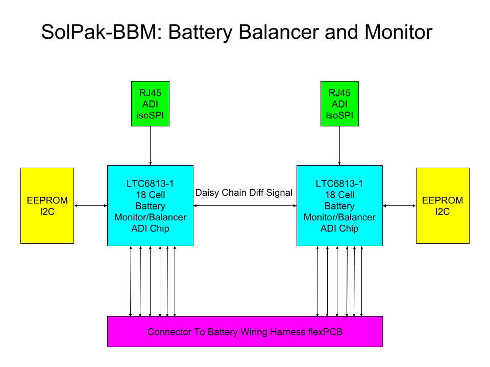
Moving on the custom board will be rather simple and very similar to the ADI evaluation board. My custom BMS board aims to duplicate the contenst of the eval kit but two times, just like the BMS boards found in the Model 3 battery. Its not a complex design, just the two chips their reference schematics, two RJ45 connectors for ISO SPI diff signals, battery connector interface, and onboard EEPROMs for each chip. I devised the overall system of my BMS from looking at the evaluation board schematics and the LTC6813-1 datasheet. These fancy BMS chips can be daisy chained together to monitor and balance 100s of cells simultaneously. The two chips my custom BMS board will be daisy chained together, and connected to the RJ45 connectors for daisy chainging multiple BMS boards for multiple battery pack modules. Here is the proposed block diagram:
![]()
There is still a ton of work to do learning how all this stuff works, I am very much out of my element in this subject compared to past projects but its very exciting. This is also one of the first projects I've started working on where I dont have the entire system 100% figured out from the beginning, I'm dong a lot more learning on the fly with this one than the others so bare with me. On another note this project is a tremendous challenge but the pay off to me is enabling more people to have access to advanced battery technology. I'm sure in time battery pack modules from the model 3 will be available 2nd hand in junkyards but what about the rest of the world, I may not be able to clone it outright but I'm hoping to get close enough and share it all on here for everyone to have. Stay tuned folks, the fun is just beginning to start!
-
Updates and Progress
07/14/2018 at 22:11 • 0 commentsSo its been a while since my last update but rest assured I am still working on the SolPak!! In the meantime I've been doing a lot of thinking/brainstorming about the pack design. Most of my efforts have been focused on narrowing down how many batteries and in what configuration as well as designing a case to hold it all together. When I'm done designing the physical pack I'll turn my attention back to the balancer/monitoring electronics.
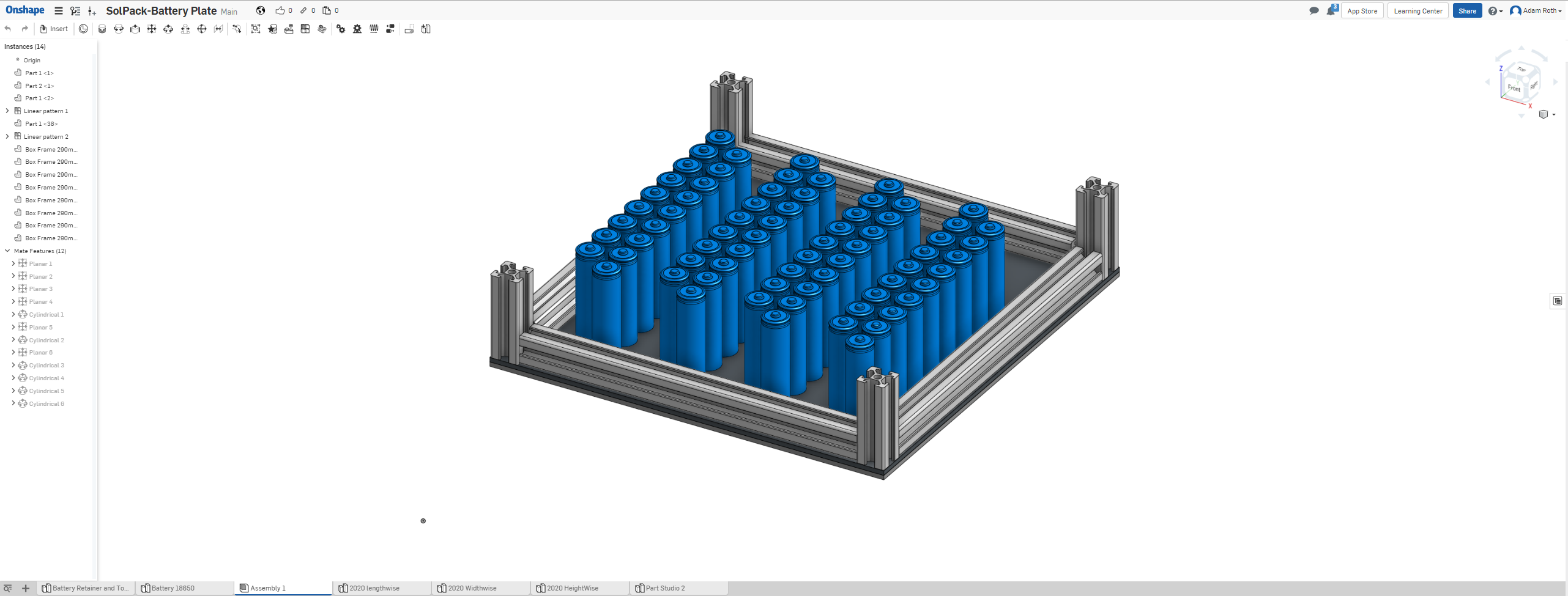
For the most part the mechanical design of the pack hasn't changed much from my proposed diagram. Since the original post I have done bit more research notable reading Jack Rickards EVTV blog posts on the subject of the model 3 battery. I'm going to do my best to emulate the Tesla design as much as possible with DIY parts and fabrication methods. Right now I have a working CAD model in OnShape of the pack.
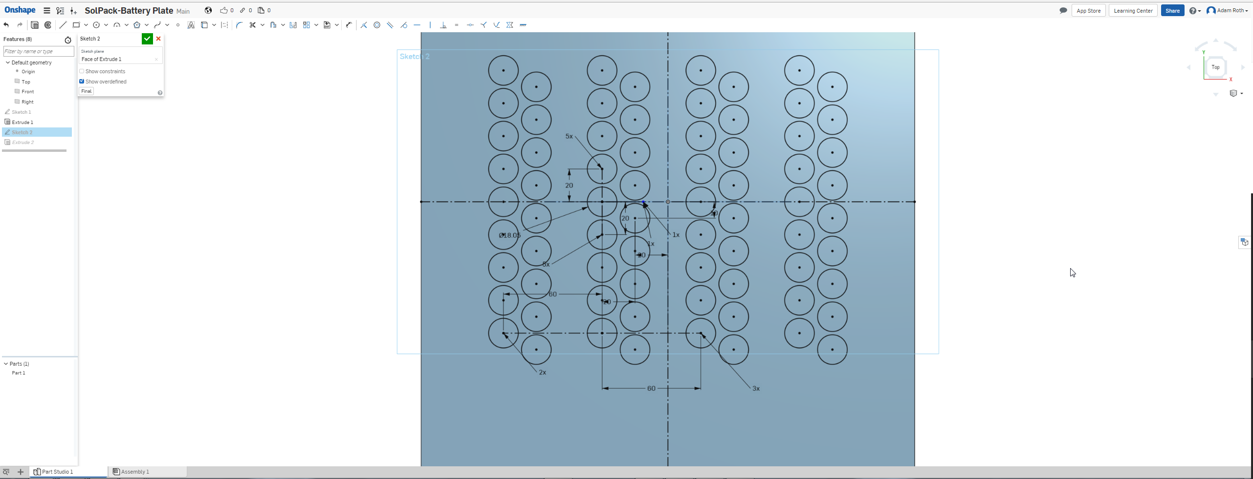
The design's bas is two 1/8in carbon fiber sheets. One has holes to mount the batteries the other has octagonal cutouts to keep the batters from falling through. The two sheets are sandwiched together to make one top and bottom plate for mounting the batteries. On the outside of these carbon fiber battery mounting plates will be stamped sheetmetal conduits for wiring the batteries together. I'm still working out my wiring configuration and what not so bear with me. These two mounting plats will hold together 72 18650 lithium ion batteries in 4 banks of 18. This pack configuration will require two balancer/monitor boards. The boards will be mounted in a space behind the batteries.
Here is what the CAD is looking like so far:
![]()
Defining the Geometry to mount batteries in the plate.
![]()
In Progress Assembly of battery pack. 72 battery cells currently mounted in module.
As you can see there is substantial space between the groups of batteries. The space is so that the cooling ribbon/piping can run through, its intended to snake through and around each bank of 18 like the block diagram in the last project log. As for what material I plan to use for the cooling ribbon piping, my plan right now is to make a jig for an arbor press so I can flatten copper pipe and bend indentations in the shape of the battery into it. I'm hoping to use a single long piece of copper pipe and careful metal-work it into shape. I'm still researching the cooling system so the idea is subject to change but the working plan is to sculpt copper pipe with an arbor press like a mad man.
So right now the CAD model is basic but there's more to the design. The carbon fiber sheets will bold onto a 2020 aluminum extrustion frame, or should I say the panels and the frame will sort of support eachother in their construction. I'm going this route since I have lots of the material on hand, its easy to cut and assemble. The box frame will be plated in carbon fiber sheet and look like a big carbon fiber box. I'm hoping to finish a decent amount of the mechanical model and get block diagrams for the electricals together by the end of the weekend.
-
Battery Bank Design
06/12/2018 at 02:09 • 0 commentsToday I spent some time brainstorming the design of the battery bank in the pack. As mentioned before I am wiring up two banks of 18 18650 lithium ion cells. I have decided on the wiring configuration as of yet. The two banks will each be monitored by the battery monitoring and balancing board that will have LTC6813HLWE-1#3ZZPBF for each bank.
Not going to lie most of my inspiration today came from looking at lots of model S battery teardown pictures. I'm taking more inspiration from the model S since theres more info out there and it uses the 18650 cells. I guess in essence I'm combining the battery management of the model 3 with the cell tech of the model S but I'll get back to the main point. The main point being is when you pack a bunch of these lithium ion cells close together in a sealed containter they are going to get hot, they need to be cooled. The Tesla Model S packs are liquid cooled, I will be applying this method of cooling to the solPak as well. I'm not sure how I'm going to exchange the heat from the battery cells into the water yet but I'm working on it. I'm thinking some thermally conductive material that can conform to the batteries somehow, either running fluid through it or coupling it to piping.
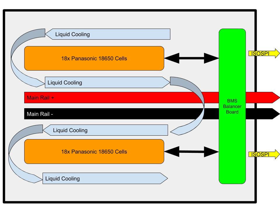
So I have these battery banks, a board, and a liquid cooling system, what I'd like to do is package it all as a sub module, like in the following diagram:
![]()
The batteries will wire into the main rails, which I plan to make from copper barstock from mcmaster-carr, and will also be wired to the BMS/balancer board. The liquid cooling heat exchanger blocks will wrap around and sandwich the battery banks. All this will be packaged as a sub module. The idea being that many of these modules can be used to make a very large battery pack. Thats all I got for today!! Next post will be discussing the BMS board, wiring of banks and more details on the electricals, this project is building slowly as I am learning almost everything as I go!
-
Introducing SolPak for the Energy Harvesting Challenge!!
06/09/2018 at 20:37 • 0 commentsSolPak is a rechargeable portable battery pack that can be charged via solar panels or AC mains voltage. The pack uses 18650 lithium ion cells and will be using the ADI LTC6813HLWE-1#3ZZPBF battery balancer/monitor chip suspected to be used by Tesla in the model 3 pack. SolPak will have modular output modules where different DCDC converters or DCAC converters can be swapped in based on end application use. The pack is intended for portable powering of devices, off the grid solar power, portable solar for camping longterm, and custom EVs.
The overall system in the pack consists of the following:
- Battery Banks (x2)
- Batter balancer/monitor/charge controller board
- Overall system control board
- Swappable output converter module interface
- Cooling system
The battery banks will consist of 18 18650 lithium ion battery cells, there will be two banks in the first prototype. The battery balancer, monitor, and charge control board will consist of two LTC6813HLWE-1#3ZZPBF for monitoring and balancing each bank, the chips can interface with each other to balance all cells together. The cooling system will be integrated in with each battery bank. Right now I am planing copper tubing attacked to copper plate pressed against and between the cells to cool them as loads of current is drawn. The liquid in the copper pipe will be pumped through a radiator or some passive heat exchanger. In the event of a radiator there will be fans. I'm still developing a solution for the charge controller portion, be I'll have it ironed out in the week. The overall system control board will be based on a STM32 MCU, it will talk to the battery board and the converter module interface, it will run the main firmware that marries together all the subsystems. The swappable output converter module interface is meant to allow the user to choose the outoput voltage for the end application. Swap in a DCAC inverter for 120VAC power to run your laptop or xbox while camping. Swap in a DCDC converter to power your robot etc.
All this good stuff is going to be mounted in either a custom case made from carbon fiber sheet cut on a CNC with brush aluminum panels here and there or I'll get some off the shelf flight case and use that. What I really want to do is build a frame out of 2020 aluminum extrusion with carbon fiber panels on the sides and to mount everything to the carbon fiber panels, then plat the outside with bushed aluminum sheet. Have holes cut for the radiator and fans to breath.
So far I have ordered a bunch of 18650 cells and I'll be diving into the length datasheet for the LTC6813HLWE-1#3ZZPBF. Once I understand the balancer chip I can choose components and putt together a PCB to be made. Once I get the battery cells I'll be able to get a good idea for how to design the case. I have aluminum extrusion laying around and carbon fiber sheet has gotten cheap so we'll see what happens. Stay tuned folks!
Happy Energy Harvesting Challenge Everyone!!
SolPak
Open Source Tesla style battery pack for EV, Robotics, and off the grid living. Modular design for multisize packs