 davedarko
I would have preferred to use one of the many spare arduino pro micros, but the arduboy gang used pins that aren't broken out on. So I've bought 2 TQFP atmega32u4 chips and started to design a board.
0%
0%
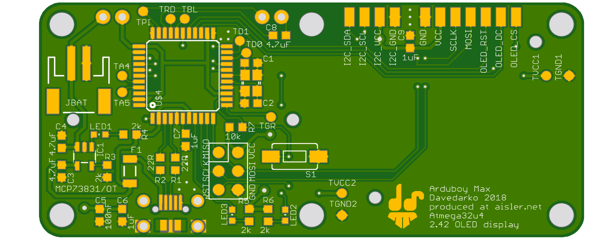
Arduboy MAX
using a 2.42" OLED display and Game Boy buttons with a diy board around the atmega32u4
Become a Hackaday.io member
Already have an account? Log in.
Just one more thing
To make the experience fit your profile, pick a username and tell us what interests you.
Pick an awesome username
hackaday.io/
Your profile's URL: hackaday.io/username. Max 25 alphanumeric characters.
Pick a few interests
Projects that share your interests
People that share your interests


You must have taken measurements of those plastic parts for the d-pad and buttons — I wonder if you still have them somewhere? I'm considering using them for my project, but I really don't want to order one of each kind, and the wait for them, just to take measurements. In particular, I wonder what the clearance between the PCB and the front plate is?