 davedarko
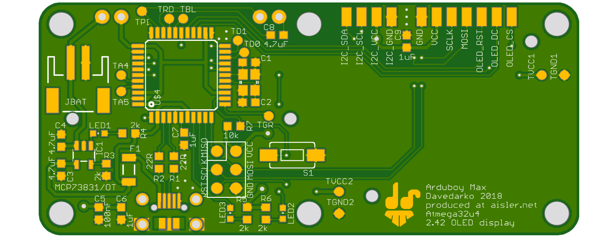
They've contacted me via instagram - like oh so many pcb fab houses do these days - and offered a free run - couldn't say no! I've added test points to attach the RGB LED, not so keen on using it, but wanted to have the option. The display will be soldered via wires. There's no battery protection on it, only a charger. Extra pads for I2C. Additional test points for vcc and gnd. Buttons will be classic Game Boy pads.

Discussions
Become a Hackaday.io Member
Create an account to leave a comment. Already have an account? Log In.
Wait, are you powering it directly from the battery without any voltage regulator?
Are you sure? yes | no
There's a regulator on it, but no level conversion - I think I can get away with it by adding 100R resistors in between the signals. It's all taken from the arduboy schematics, and now that you ask I feel a bit stupid not checking again o.O it's not to late to update at aisler.
Thanks for calling it out!
Are you sure? yes | no
Nice!
Are you sure? yes | no