deʃhipu
-
CircuitPython Fixes Timer Bugs, Requires Redesign
05/07/2019 at 10:17 • 0 commentsIt turns out there have been some bugs in CircuitPython's pulseio module, related to how it selected what timer/channel to use for PWM for each of the pins. Long story short, it would sometimes re-use the channels that were already in use, resulting in those pins sharing duty cycle — you change it on one of them, it changes on the other as well. Obviously that's not good for us. The good news is that the bugs have been all fixed now. The bad news is that it's not possible anymore to have a PWMOut created for all the pins I'm using for servos at once — it was possible only because of that bug...
That means I need to redesign the PCB to use a set of 12 pins for the servos that can have PWMOut created for them all at once. To do that, I will need to do more testing to determine which pins I can use, and there is always a possibility that I don't find such pins — in which case I will need to switch to a bigger package, and possibly also a SAMD51 chip.
I also need to rethink the battery charging circuit — I want to keep the robot off while it's charging. Would also be nice to add that flash memory chip, for extra filesystem space for all the files.
I think I will drop the accelerometer in the process, because it turns out to not be that useful. I will also give up on the idea of keeping the top of the PCB clean and fitting all the components inside the hole in the battery holder — that was an interesting, but ultimately pointless challenge. I still want to have all SMD parts on one side of the board, though, because that makes assembly easier and cheaper, so they will probably all go on the top, with only THT parts on the bottom.
-
Immediate Plans
12/21/2018 at 14:55 • 0 commentsI had a bit of a break with this project, while I worked on other projects and dealt with some life stuff, but I very much still want to work on it. Obviously the very next step that needs to be done is to program the robot to do actual walking, at least at the level of #Tote, and then possibly make use of the accelerometer and the leg switches. I assume that this will actually take me some time. In the mean time, CircuitPython is being developed further and ported to the NRF52 chip, growing bluetooth support along the way, so the long-term plan is to switch to NRF52 from the SAMD21 chip. That will probably involve a redesign of the extension connector as well, so I don't think I will be working on any extensions until that happens.
Once the connector design is finalized, it will be time to look at possible extensions and the sensors to include on them. I want to have an OpenMV adapter, and also a simple "face" with distance sensors on it.
-
Build Instructions
09/20/2018 at 07:02 • 0 commentsSince there is now at least one person trying to build this robot, I'd better post some build instructions. I don't have a full-blown material with photos yet, but I will try to make it workable.
So, first, what you will need:
- the assembled robot PCB, with the battery holder
- 12 SG90 microservos
- 24 tiny screws (I forgot to attach them to the PCB, sorry)
- 4 larger screws (you can use the ones that come with the servos)
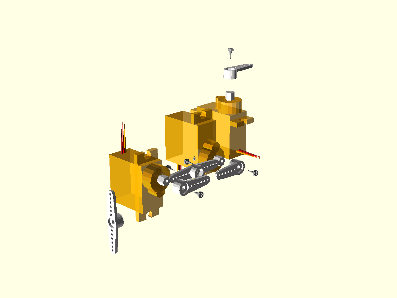
To assemble the legs, first hot-glue four pairs of servos together to form the hips. You will need two "left" and two "right" pairs. The whole leg goes something like this:
![]()
And two of them will be a mirror image of that. Don't put in the screws that hold the servo horns, you will need to adjust the servo positions first.
Connect the servos to the PCB. There are helpful markings on it, such as "FR1" (front right 1) and "HL3" (hind left 3). The number goes 1 for ankle, 2 for knee and 3 for hip. The ground pin is marked, the middle pin is power, and the last pin is signal. You can use male pin headers and plug the servos in, or cut the cables and solder them directly. I prefer the latter, because then you can adjust the wire length and have better cable management. Make sure to leave some extra cable length for the leg to be able to move freely.
Once you have that, you can connect the robot to USB and create a main.py file with the following contents:
import board
import pulseio
import time


_PINS = (
        board.SERVO_HL1, board.SERVO_HL2, board.SERVO_HL3,
        board.SERVO_FR1, board.SERVO_FR2, board.SERVO_FR3,
        board.SERVO_FL1, board.SERVO_FL2, board.SERVO_FL3,
        board.SERVO_HR1, board.SERVO_HR2, board.SERVO_HR3,
)
servos = tuple(
    pulseio.PWMOut(pin, frequency=75)
    for pin in _PINS
)
for servo in servos:
    time.sleep(0.25)
    servo.duty_cycle = 6300

while True:
    time.sleep(1)
That will set all the servos to their middle positions. Disconnect the robot, insert the battery (mind the polarization) and switch the robot on. Now remove each servo from its horn and insert it back, making sure it's at a right angle to the horn. Secure the horns with the screws.
That gives you a finished physical robot.
I still didn't write the programs and libraries for it — I will be writing updates here when I do.
-
New Legs Assembled
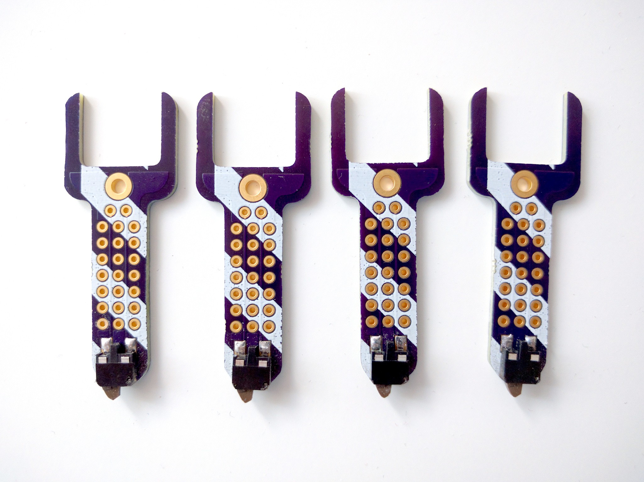
08/10/2018 at 18:15 • 0 commentsThe PCBs arrived, and I have soldered them up:
![]()
I also rounded the corners of the switches a little bit, so that they better touch the ground.
-
Improved Legs
08/03/2018 at 08:58 • 0 commentsOne of the advantages of having the legs made out of PCB is that you can easily put things on them. Like, for example, switches that detect when the leg is touching the ground. I didn't include that in the original design, because I was a bit in a hurry, but that's not a problem, since I can make a separate set of legs easily.
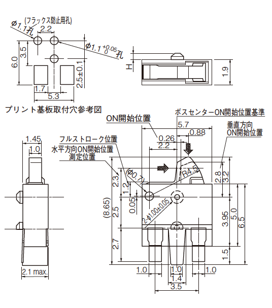
It's a bit problematic to find the right kind of switch for this. For one, it has to be edge-mounted, but more importantly, it has to require very little strength. Regular "tactswitch" buttons are useless for that, but if you look around carefully, you will find something that is labeled "card detection switch" — those switches are supposed to detect when something, such as an SD card, is inserted into a slot. As such, they are rather sensitive, requiring very little force to be pressed. And they are usually in the correct orientation.
One such switch is the Panasonic ESE22MH27 that I happen to have in my drawer. A quick search for images reveals this footprint image:
![]()
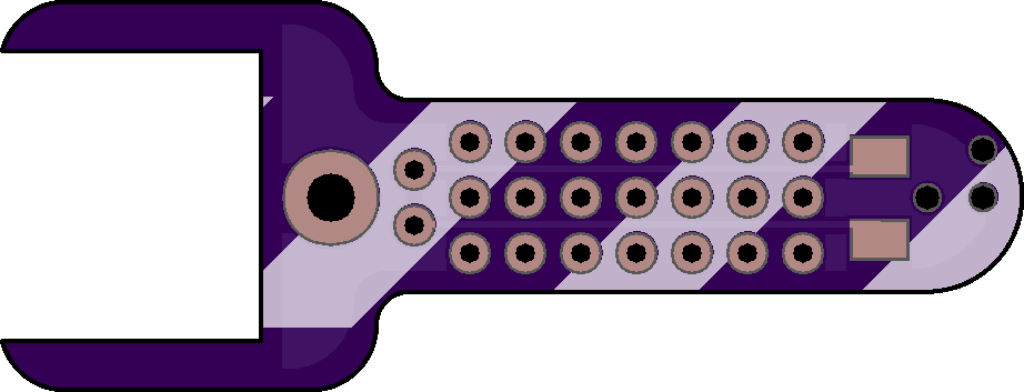
So I quickly made a PCB with the footprint, and added some prototyping area to the leg, for good measure:
![]()
One annoyance is that I need 4 of those, but OSHPark makes them in batches of 3, so I need to order 6. At least I will have some extras to break.
-
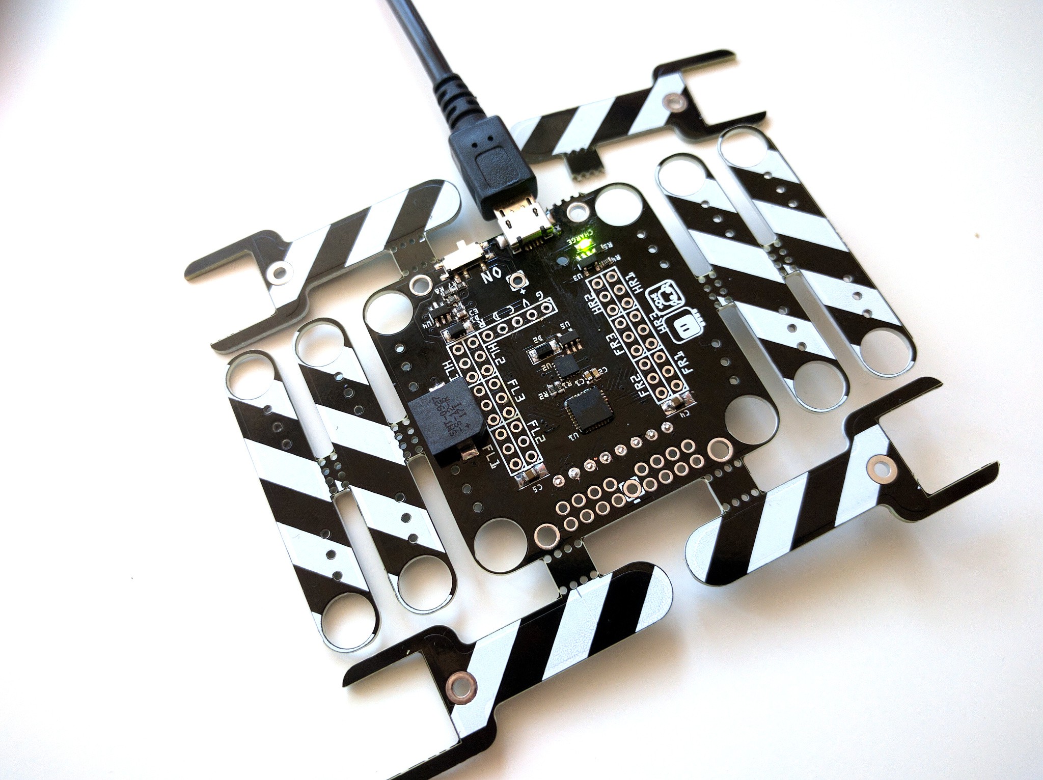
Assembled PCB
06/25/2018 at 22:20 • 1 commentI assembled a second PCB, this time without first breaking off all the bits of the legs, to see how it will look and feel. I actually had to break off one piece, to get to the USB port.
![]()
However, if I'm going to sell those, I think I will break all the bits off, and put it all in a bag. It will be smaller that way, and less fragile.
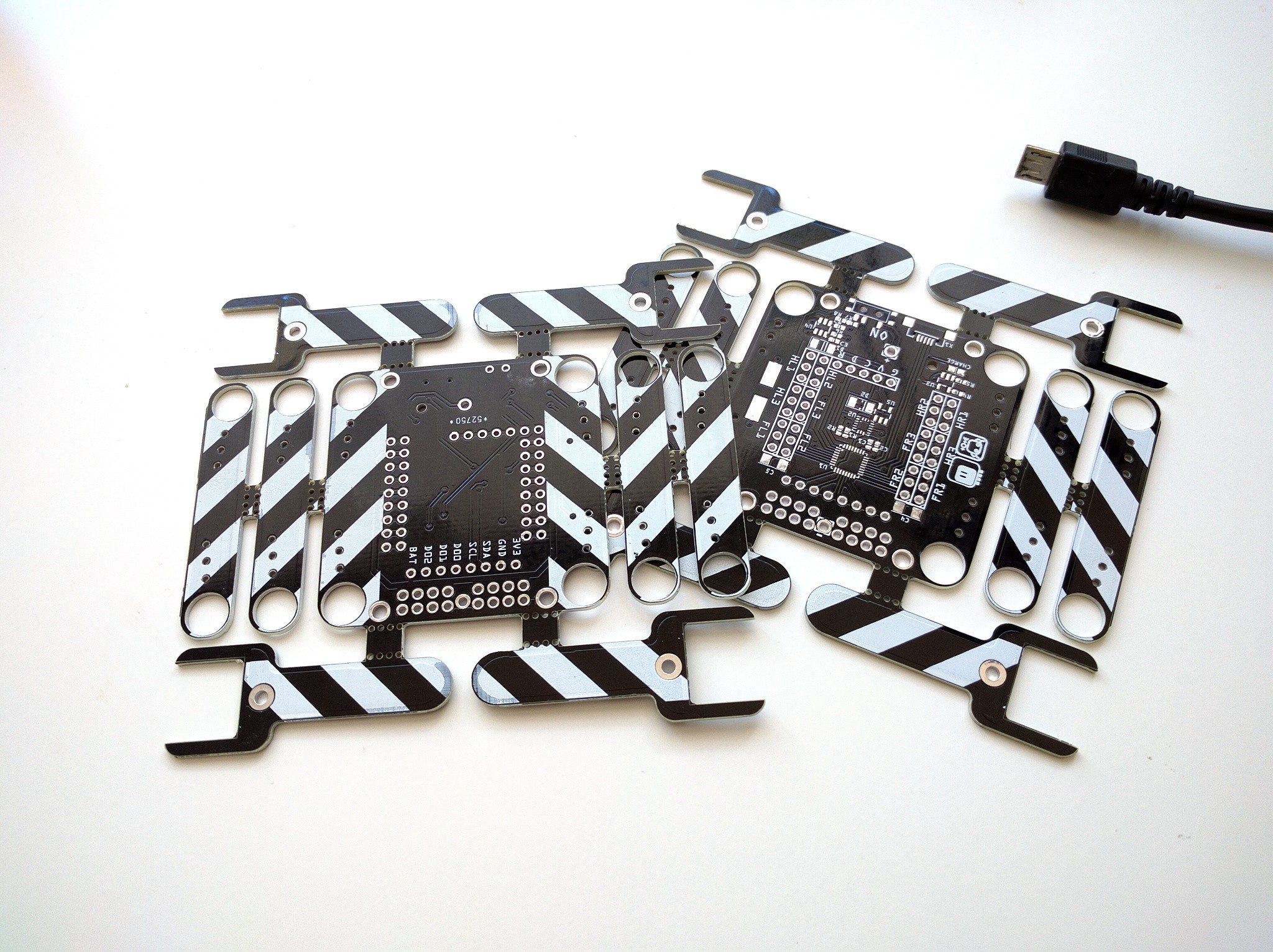
I still can't decide whether I want to ship with the battery holder and servo headers soldered or not. Having them soldered allows people to more easily assemble it, but makes the package thicker, and makes cable management tricky. If the headers are not soldered, they can cut the servo cables to the right length and solder them directly into the board, like I did with the first prototype:
![]()
On the other hand, since the battery holder has its cross-section roughly square anyways, the package has to be pretty thick to fit it no matter if it's soldered or not.
-
First Prototype
06/22/2018 at 22:46 • 0 commentsThe PCBs from DirtyPCBs arrived today — pretty fast, I have to admit!
![]()
I got one of them assembled. The microcontroller worked first time, but I had to do several resolderings before I got the accelerometer to work. Seems like one of the pins in my gerbers is weird — probably another Fritzing bug. But no that I know it's there, I can scrap it a bit before soldering and it should be fine.
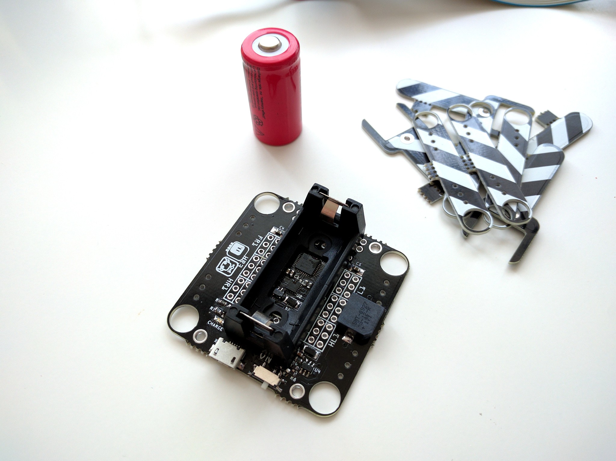
![]()
As you can see, everything fits neatly inside the hole of the battery holder, and around it. I decided to use a large, good quality speaker this time — maybe I can have it say the turret lines from Portal. Next up are the legs. Unfortunately that part still requires the use of hot glue.
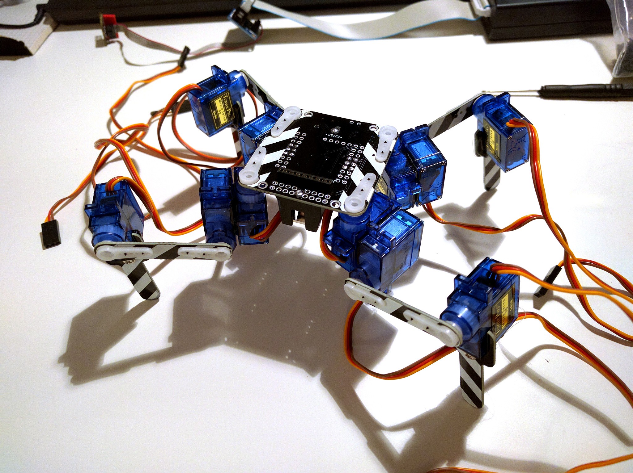
![]()
I got the first four servos connected — since I don't want too long cables, I decided to cut them and solder them directly into the PCB, but you can as well solder male headers in there and plug the servos in. There is room for that.
I compiled a version of CircuitPython for Trinket M0 with adjusted pins, and the servos work nicely! Now I need to connect the remaining servos, and port the IK code I have to this.
-
Penalized Panelizing
06/12/2018 at 19:30 • 0 commentsTurns out that my simple yet brilliant idea for using the remaining board space for the mechanical parts of the legs is not so great after all. Most of the board houses noticed that people cram multiple designs into their boards, and started to demand extra payment for them. For example, at jlcpcb, you pay $2 for the first order, and $8 for every additional design on the same board, while ordering a separate PCB with that other design would cost you $5... Crazy stuff.
I decided that I won't be participating in that, and simply went to DirtyPCBs, who don't do such a thing. But they use white silkscreen with the yellow boards, which would look bad with the diagonal stripes that I added, so I ended up ordering black PCBs. Oh well.
Ultimately, I probably want to laser-cut the mechanical parts anyways, but I really wanted to test how this would work.
-
Take Over the Wold Already
06/10/2018 at 20:23 • 0 commentsI decided to take all that I have learned in the recent years with all the versions of #Tote and other projects, and turn it into a robot kit to sell on Tindie. While the previous work focused on making it as simple as possible to build it yourself and possibly modify the design, this time I'm going to focus on optimizing for a kit. The design will be much more integrated, with all that can be done in advance already done. I'm going to optimize for the cost, ease of production, shipping, ease of assembly, robustness, and fun. Of course I still want to make it easy to hack and extend, but that is going to be a secondary concern.
Optimizing for cost and ease of production means that the development boards, as used in #SpiderWing and #D1 Mini Tote have to go — not only they add to cost, but also they increase the risks, because I don't have any guarantee they will still be available in two years in reasonable prices. So it has to be a single integrated circuit board, with a minimal amount of through-hole parts, with all the parts on one side, and fitting in either the 5x5cm or 10x10cm limit.
Optimizing for shipping means that it can't be sold assembled — the box would simply be too big. So the kit has to be flat, preferably less than 2cm. There is no chance I'm going to ship a battery, so it has to use a standard battery that is easy to get. And the servos are simply too heavy to ship, so that will need to be sourced separately too.
Ease of assembly means that everything has to be pre-soldered. Soldering is not hard, but requires specialized tools and people are afraid of it. It also means that it has to come pre-programmed, and that there needs to be a simple procedure for calibrating the legs. I would love to avoid glue if possible, but we will see how that works.
Robustness to mistakes is important, because I have limited time I can devote to support — ideally it should just work, and if it doesn't, there should be a simple procedure to follow to figure out what is wrong. The fear of having to support hundreds of people whose robots don't work is what stopped me from selling a Tote kit on Tindie so far, but now I decided to try my luck. It doesn't mean I can't try to make it as easy as possible for me.
Finally, it has to be fun out of the box, otherwise people will just assemble it, see that it works, and put it back into the drawer. If it's fun, there is a good chance of someone deciding to hack it. Because of that, it will ship programmed as a remote-controlled toy, possibly with several modes — walking, dancing, balancing, etc. But of course it's not just a toy, and it will be easy to program it and add custom behavior.