-
SOL V2 Hello World
10/02/2018 at 02:14 • 0 commentsWorking off some of the successes and failures of version 1, I recently designed and built a second version of SOL. There were a variety of goals here:
- Lower BoM cost
- Some lower cost replacement parts
- Smaller PCB size
- Smaller battery (from 16500 to 14500 Lithium battery)
- External ADC for power measurement (ESP32 ADC has known accuracy issues, discussed here)
- Use ADC with PGA for higher accuracy measurement in low-light situations
- RTC for time-stamping datapoints
- Temperature sensor (ESP32 temperature sensor is very inaccurate)
- Better mounting in case
- SOL V1 overall size was slightly wrong, so didn't fit cleanly into its waterproof case
- Easier to program -- expose IO0, IO2, and EN pins
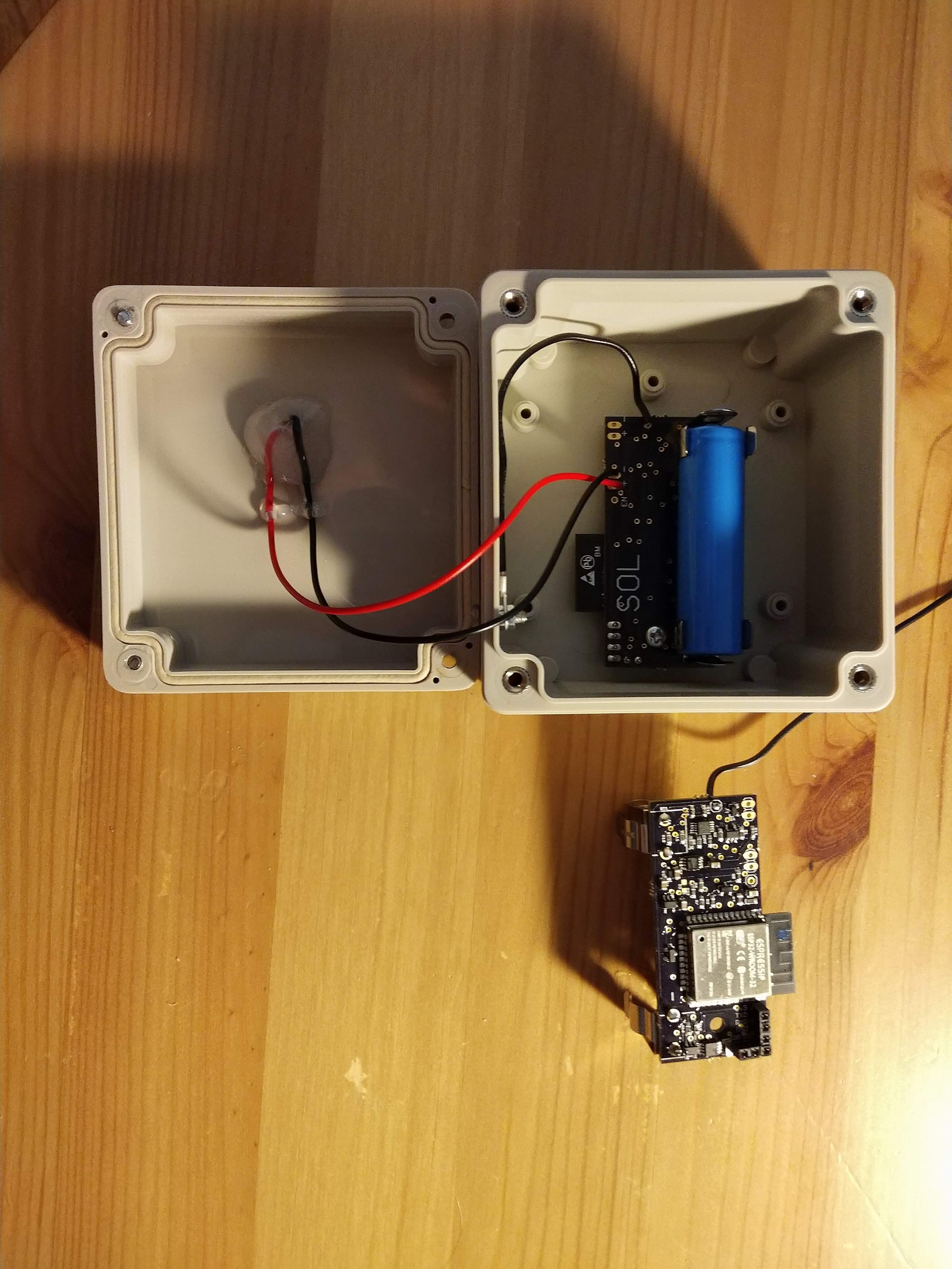
I will be adding the BoM, design files, and firmware for SOL V2 soon. For now, some pictures of the two assembled devices made so far:
![]()
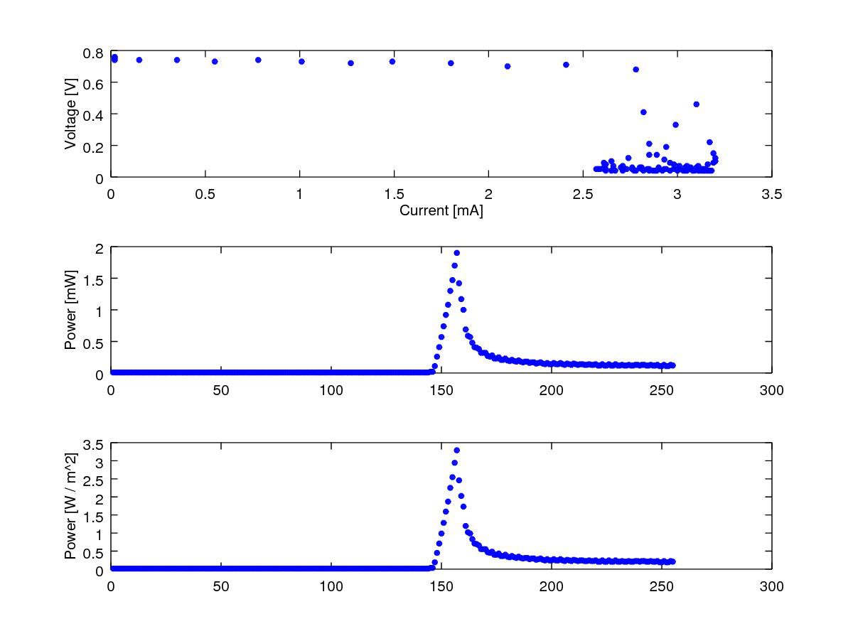
I tested the power measurement sub-circuit, using 5 difference settings of the ADC PGAs (4.096V, 2.048V, 1.024V, 0.512V, and 0.256V full scale ranges.) With the amount of light available (indoor lamp in a mostly dark room), the ADC did not saturate at any PGA level, and the scaled measurements all matched nicely. One example is shown below. A fairly typical solar panel IV curve can be seen in the top subplot. Overall, the levels of measurement seems lower than expected, but I will need to see its performance in direct sunlight to check if it is ballpark correct. For reference, at maximum power this panel should be about 5.5V and 100mA. Note the power density subplot at the bottom is assuming a panel efficiency of 15%, and it just for reference.
![]()
- Lower BoM cost
-
Finally Working
08/11/2018 at 19:47 • 0 commentsIt has been a long time coming, but the custom SOL device is finally working.
After assembling the SOL_R1 design, and charging the battery, I measured the output of the 3.3V MIC5205 voltage regulator with a multimeter as about 1.4V. After looking further at the datasheet for the MIC5205, I noticed that it is not compatible with a ceramic output capacitor. I did not have an oscilloscope on hand to examine the output waveform, but it was likely oscillating such that the averaged measurement seen on the multimeter was about 1.4V.
A few solutions seemed reasonable. One option was to switch over to the MIC5245 voltage regulator, which is pin compatible with the MIC5205 and is stable with a ceramic output capacitor. Or I could change the output capacitor for the MIC5205 to the recommended 2.2uF tantalum capacitor. I ordered both options.
Once the MIC5245 device arrived, I built SOL with it. Unfortunately, the output voltage was still bad, hovering around 0.4V. At this point I realized what should have been obvious earlier -- these voltage regulators can only supply up to 150mA, but the ESP32 datasheet recommends a power supply of at least 500mA. While the first version still would have been unstable with a ceramic capacitor as set up, the second attempt likely would have been stable, but was unable to supply enough power.
Thankfully, there is a pin-compatible 500mA voltage regulator (RT9080) which I was able to switch to without making new PCBs. After installing this part, the output voltage was a stable 3.3V!
The next step was to program the device with the SOL firmware. I used the 3.3V FTDI Basic USB-to-serial converter from SparkFun. I connected GND, TXO on the FTDI basic to RXD on SOL, and RXI on the FTDI basic to TXD on SOL. When I attempted to program the device, it did not respond. I then realized that the ESP32 needs to be put into the ROM serial bootloader mode. This website explains the process. GPIO 0 and GPIO 2 must be held low. SOL was designed to use GPIO 0 as a touchpad input, so this pin was easily accessible. For GPIO 2, I had to carefully touch a jumper wire connected to ground to the correct pad on the ESP32 module. Once I did this, the device was programmed!
I confirmed the device was able to measure power from the solar panel, was able to connect to WiFi, and was able to upload data to Google Sheets.
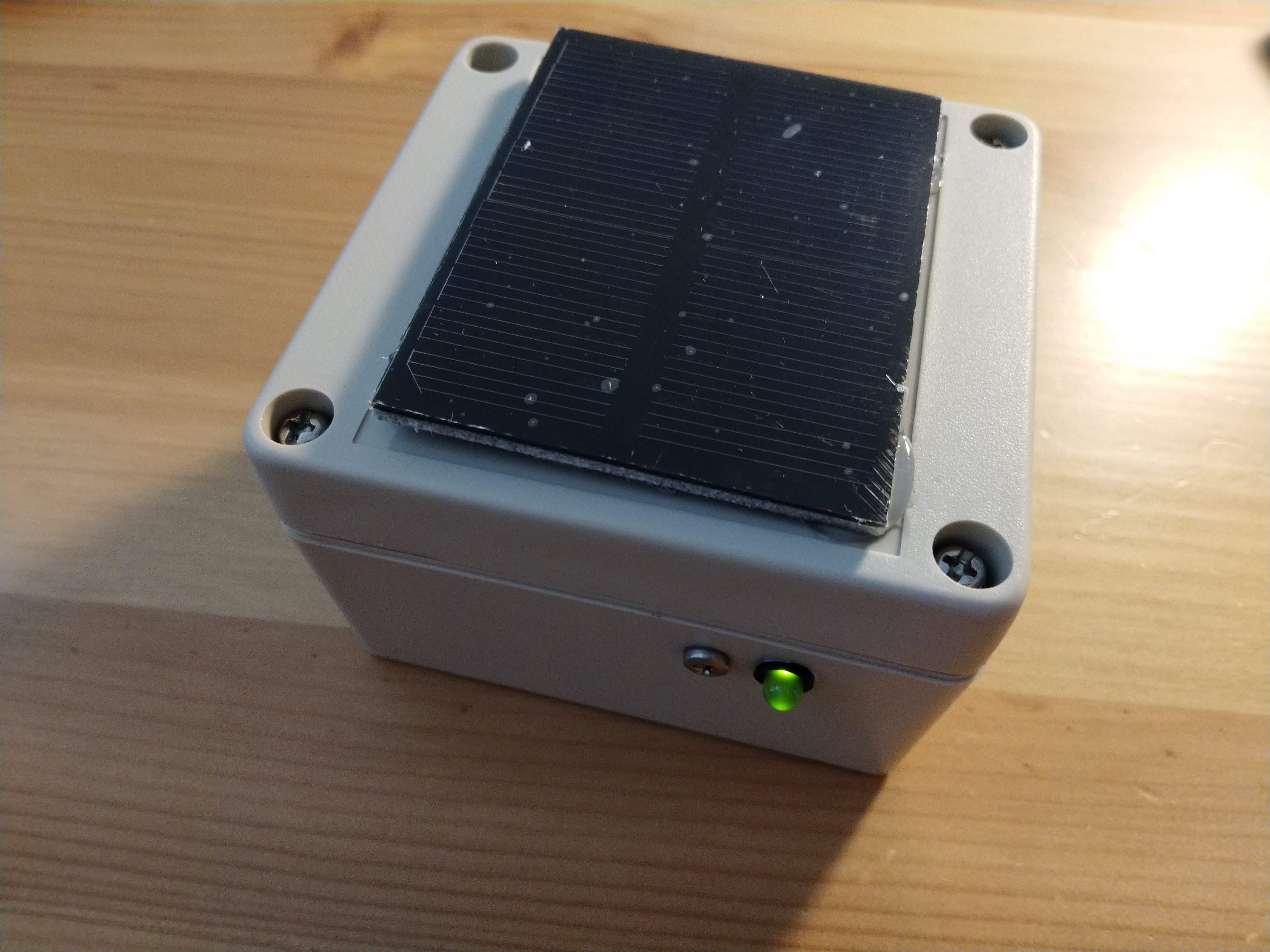
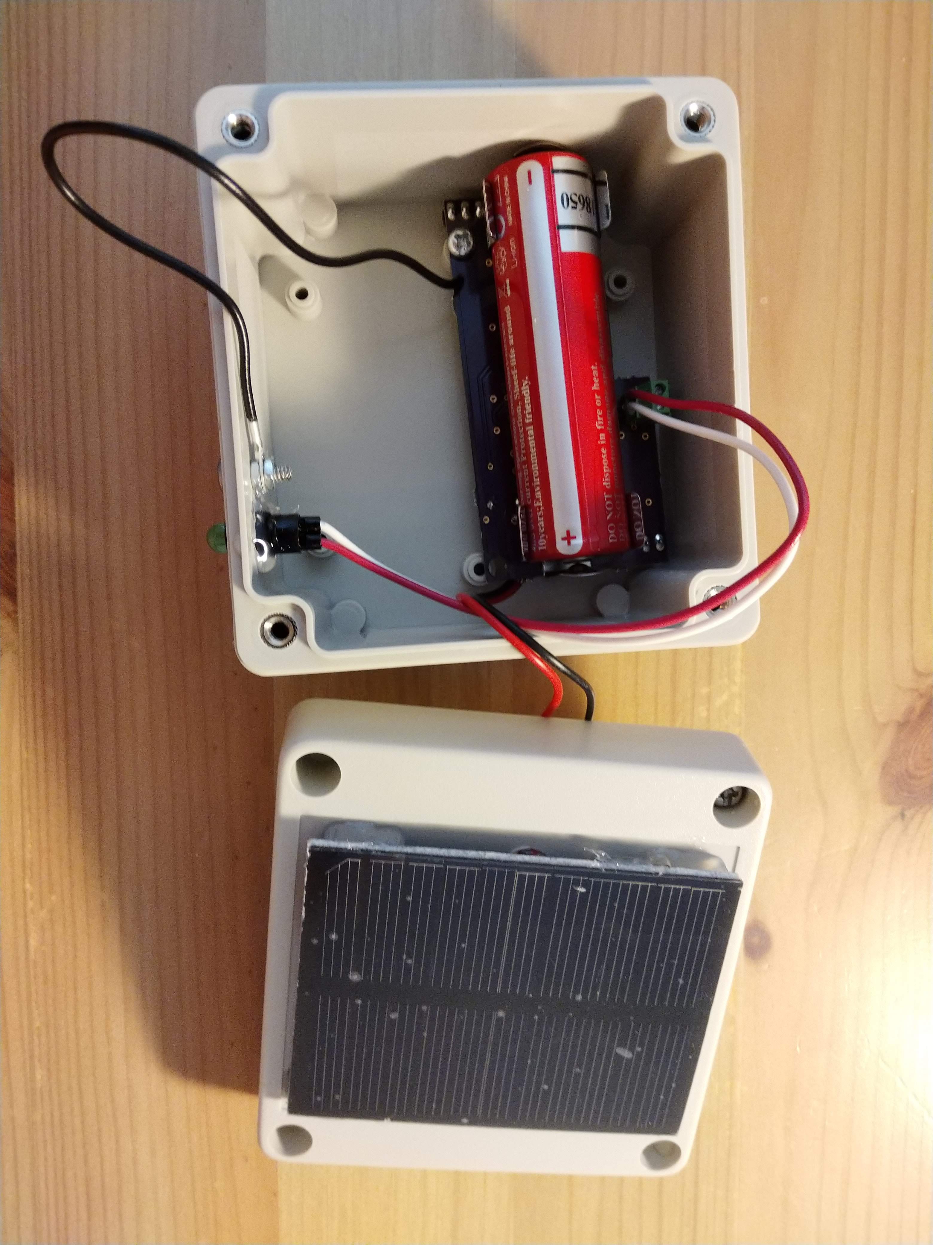
Next, I worked to assemble SOL into its case. I used an off-the-shelf IP65 waterproof case (RP1065.) I added a hole on top for the solar panel connection, and two holes on the side. One hole was for the a panel mount LED, and the other is for a bolt with gasket used as a capacitive touch input. Ideally, this setup will be waterproof, but quick testing showed some leaks. Likely this is from the panel mount LED, which does not have a gasket and is not very accessible for adding waterproofing. Making this setup waterproof will be a next step, so that SOL can be left outside.
![]()
![]()
-
Fixing the Web Side
06/24/2018 at 01:17 • 0 commentsAs discussed in the last project log, while the hardware is functional at this point, the process for entering WiFi credentials to allow SOL to connect and the process for uploading data were merely hacked together.
I updated the WiFi provisioning process to use the WiFiManager ESP32/ESP8266 library. This library provides the user a list of available wireless networks, and provides a much nicer looking interface to the user while connecting. This update is on the GitHub.
I also want to welcome Ryan to the project. He comes from a computer science background and his help in developing the web interface for SOL is greatly appreciated!
-
Source Available
06/23/2018 at 01:15 • 0 commentsAfter some cleanup and documentation, I have added the hardware files and initial Arduino compatible library for SOL to a GitHub repo (linked on main page). The sections relating to WiFi provisioning and uploading data will not remain in the future, and are simply some examples I hacked together to get the basics working. Those sections have major usability and security issues so be aware. The code also has a large amount of debugging serial port printing left in (although removed during compilation if desired).
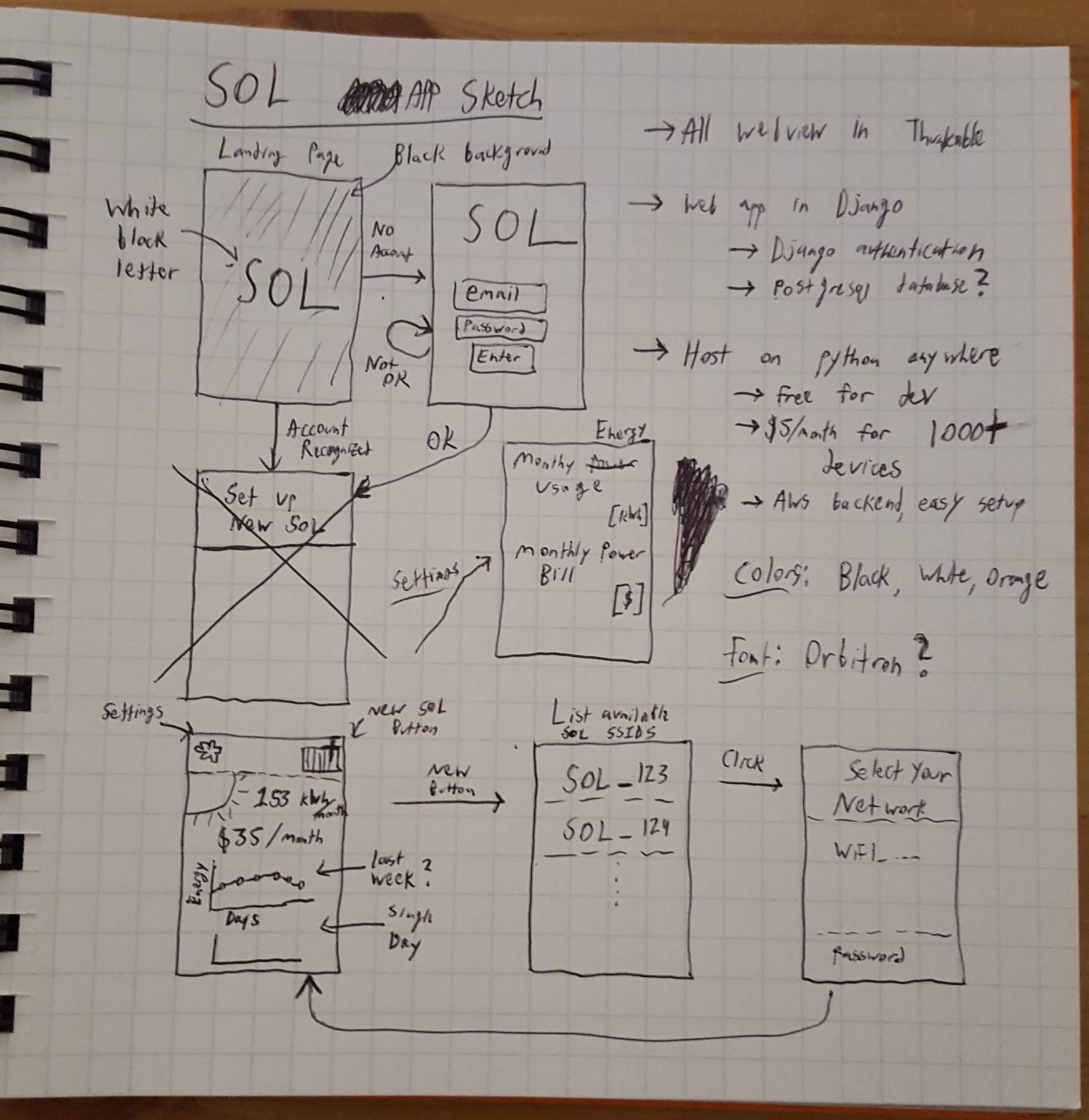
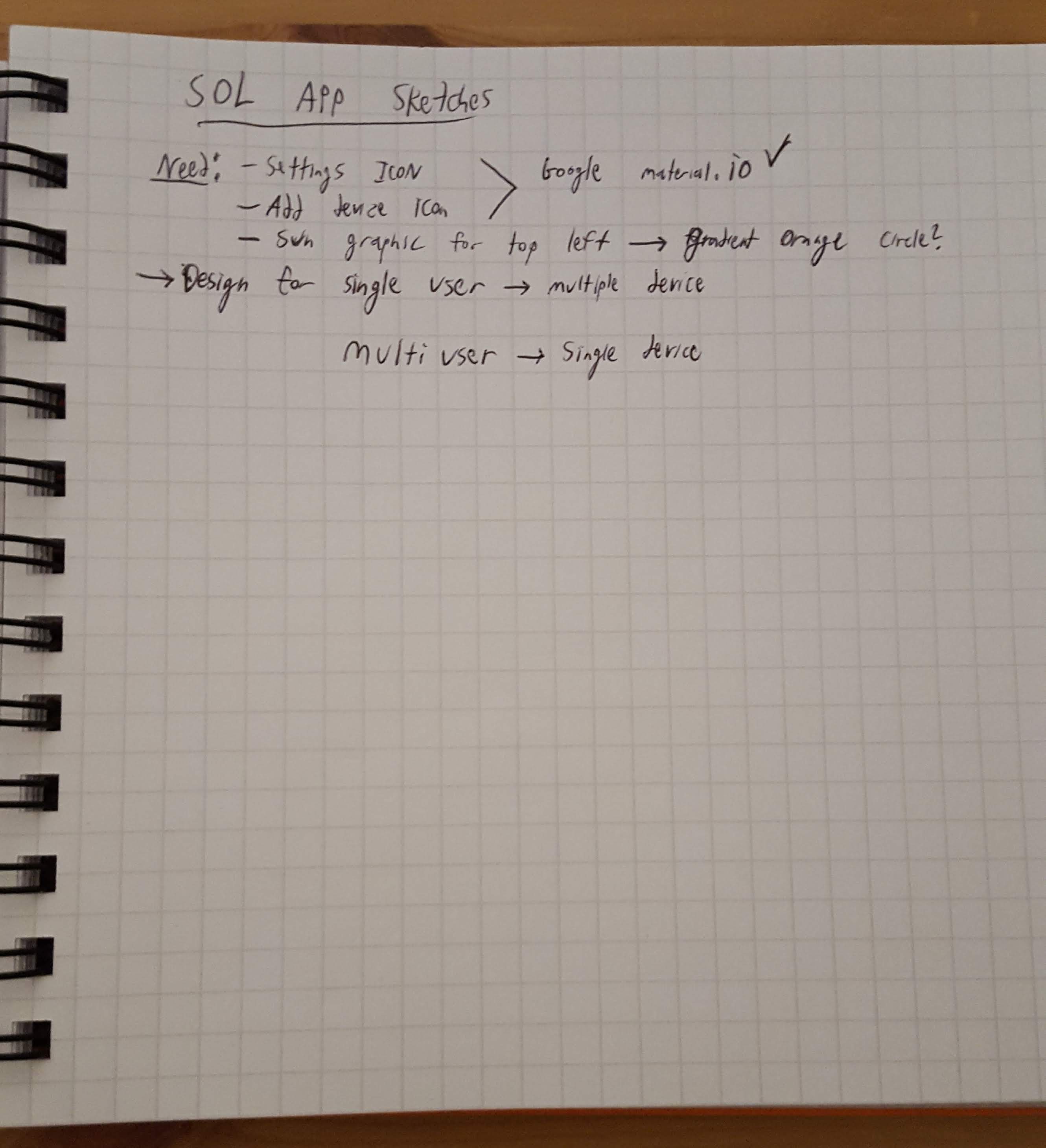
At the same time, I have been learning about web development and trying to spec out the minimum functions of a web app/phone app that SOL would require. Below are some images with results from my brainstorming.
![]()
![]()
Apologies for my near-illegible writing and drawings, but the idea is to build a basic phone app in Thunkable, which uses React native to generate native iPhone and Android apps using a simple drag-and-drop interface. Thunkable has an interface component called a webviewer, which (obviously) simply displays a certain webpage. This can be used during WiFi provisioning to point the app to the correct IP address on the SOL network where the user can enter their SSID and password. It can also be used to view data served by a web app. How that web app is built is still very unknown, but I have been doing tutorials with the python Flask and Django interfaces and Bokeh for plotting data. Python anywhere could be used to host the web app for free (for small amounts of data throughput, which should be fine for testing SOL).
-
Breadboard Prototype Development
06/16/2018 at 01:06 • 0 commentsIn preparation for the custom PCB version (parts on order), I have been working on some further improvements to the original breadboard prototype.
On the hardware side of things, it is simple. First, I attached a jumper wire to Pin #0 to act as a touch input. Second, I added a 24LC512 EEPROM chip connected through I2C. Since the ESP32 cannot keep data in RAM during deep sleep, this EEPROM acts as non-volatile storage for system status information, measured data, and the WiFi SSID and password.
![]()
I have also been working on firmware. The good news is many of the desired abilities laid out in the last development log now work. It now enters softAP mode upon touch input, hosting a webpage which allows the user to enter their WiFi SSID and password. SOL then saves that information into EEPROM. The system wakes up every N seconds to record data and save to EEPROM, and every M cycles it uploads that data through WiFi. The bad news is that many of the WiFi-side elements are merely hacked together at this point. The softAP mode receives passwords from the user in plaintext, clearly not a good idea. When it uploads the data, it does through IFTTT to a Google Sheet, requiring a hard-coded API key. Therefore it is still not yet ready, but is coming along nicely.
Next tasks to attack:
- Moving firmware to github to share here
- Improve WiFi provisioning process for security
- Determine how to handle server-side data storage (very open ended task, since I don't know what I don't know yet...)
- Determine how to handle client-side data plotting
-
Firmware Design
06/13/2018 at 01:36 • 0 commentsThanks to the hard work be many people getting ESP32 working for Arduino, most of the bits and pieces of firmware I will need for this project seem to have been developed. To name a few:
- Analog and digital input and output
- Touch sensor interrupts
- I2C library
- Deep sleep modes
- WiFi libraries
The firmware for the breadboard prototype is very simple. My WiFi SSID and password are hardcoded, and the ESP32 sends data through IFTTT to a Google Sheets spreadsheet. To calculate power, it uses the ADC and DAC interfaces. Between samples, it enters deep sleep for 10 minutes.
While I have experience developing firmware, I have very little to no experience in web development, so I will need lots more research on how to handle the networking side of things. My initial vision for program flow is something like this:
Assume system is brand new...
Deep sleep until button touched, then set up SoftAP mode on ESP32. Connect to ESP32 network on phone/laptop, and allow user to provide their network SSID and password.
ESP32 saves correct SSID and password information, and goes to sleep.
Every N minutes (maybe 10?), the system wakes up, with radio off, and samples the solar power. It saves the measurements on EEPROM. Every M samples (maybe once per day?), the system connects to WiFi and uploads its data somewhere.
The user can then, either on a web app or phone app, view data on their system.
Large questions remain. Where to send data? Set up my own server/API on e.g. AWS? Use one of the numerous IOT data storage services? I've never done any of this before, but why do a project with only things you know?
-
First PCB Design
06/13/2018 at 01:21 • 0 commentsWhile the breadboard prototype helped prove out the electronic load design concept, there are numerous features that does not include. It cannot use the solar panel to recharge its battery. It is not in any way enclosed, so it cannot be placed outside in direct sunlight. It does not have any buttons or LEDs for user input. Finally, it does not have nonvolatile storage for data, which could be used to allow the system to wake up and sample much more often than it uploads data over WiFi, which would save power immensely while increasing sampling rate.
These issues were worked out for in a custom PCB design. It still uses the same electronic load circuit, ESP32, and solar panel, but adds charging ability, LED indication, touch sensor input, and 512 kbit of EEPROM storage. The board includes clips for a 18650 lithium battery, and is designed to be mounted in a COTS waterproof box, so it could be placed outside.
The design files have been uploaded. After review with fresh eyes I will get the parts on order!
-
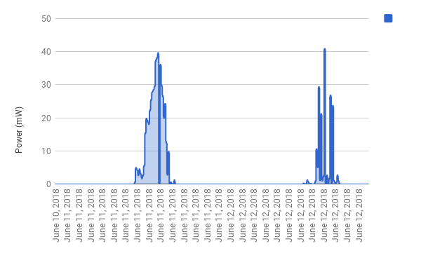
First (Indirect) Sunlight Data
06/13/2018 at 00:54 • 0 commentsI set up the breadboard prototype shown in the first project log with the solar cell pointed out of my apartment window. It is receiving sunlight at a very poor angle, through a window, and likely cannot ever receive direct sunlight due to trees on the street and nearby high buildings. Nonetheless, during parts of the day, non-zero power was recorded, seen below. Curiously, occasionally the power drops to zero, especially on the second day. Some storms came through June 12th, so probably the sun was occluded enough that no measurable power was seen.
![]()
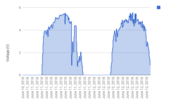
The solar cell produces nonzero voltage even in very low light, so the voltage plot below provides a better idea of sunrise and sunset. It also is more constant, even if clouds come through.
![]()
-
Early Prototyping
06/11/2018 at 01:47 • 0 commentsThere are a few global requirements for SOL, some obvious, some not:
- Ability to sense solar power intensity. This requirement is of course the whole point of the project, but there are numerous methods for doing this.
- Long-term use. The system must have low power consumption and/or solar recharging to allow the system to run for at least a year on its internal battery alone.
- Connectivity. The system must have wireless connectivity to easily allow the user to view data on solar intensity over time.
After some brainstorming, I determined a basic design for SOL. The system will have a small solar panel, to be used both as a battery charging source and a sensor. SOL will be a photovoltaic pyranometer. At each sampling interval, it will perform an impedance sweep on the solar panel to determine its maximum power point at that instance in time. Between sampling intervals, the solar panel will be connected to the charging circuit and the microcontroller in SOL will be in low power mode.
To perform the impedance sweep, a simple electronic load using a MOSFET in its linear region is used. A DAC provides the gate voltage sweep on the MOSFET, while two ADCs monitor voltage and current from the solar panel.
The ESP32 microcontroller was chosen for use due to its wifi/BLE connectivity, ULP modes, ADCs, DACs, and low cost. The ability to program it through the Arduino ecosystem also enables quick development.
The Seeed Technology 0.5w solar panel was chosen due to its adequate power in sunlight for charging the system, and low cost.
This solar panel has a maximum voltage of 8.2V. The rated maximum power point is at 5.5V and 100mA. Operating near this point is most critical for SOL. Solar intensity in low light can be many orders of magnitude lower than in direct sunlight, but accurate measurement in low light is not critical, since very little power is available.
For this solar panel, the voltage can be measured by the ESP32 ADC through a simple voltage divider. The current is measured as a voltage across a shunt resistor, amplified through a non-inverting amplifier.
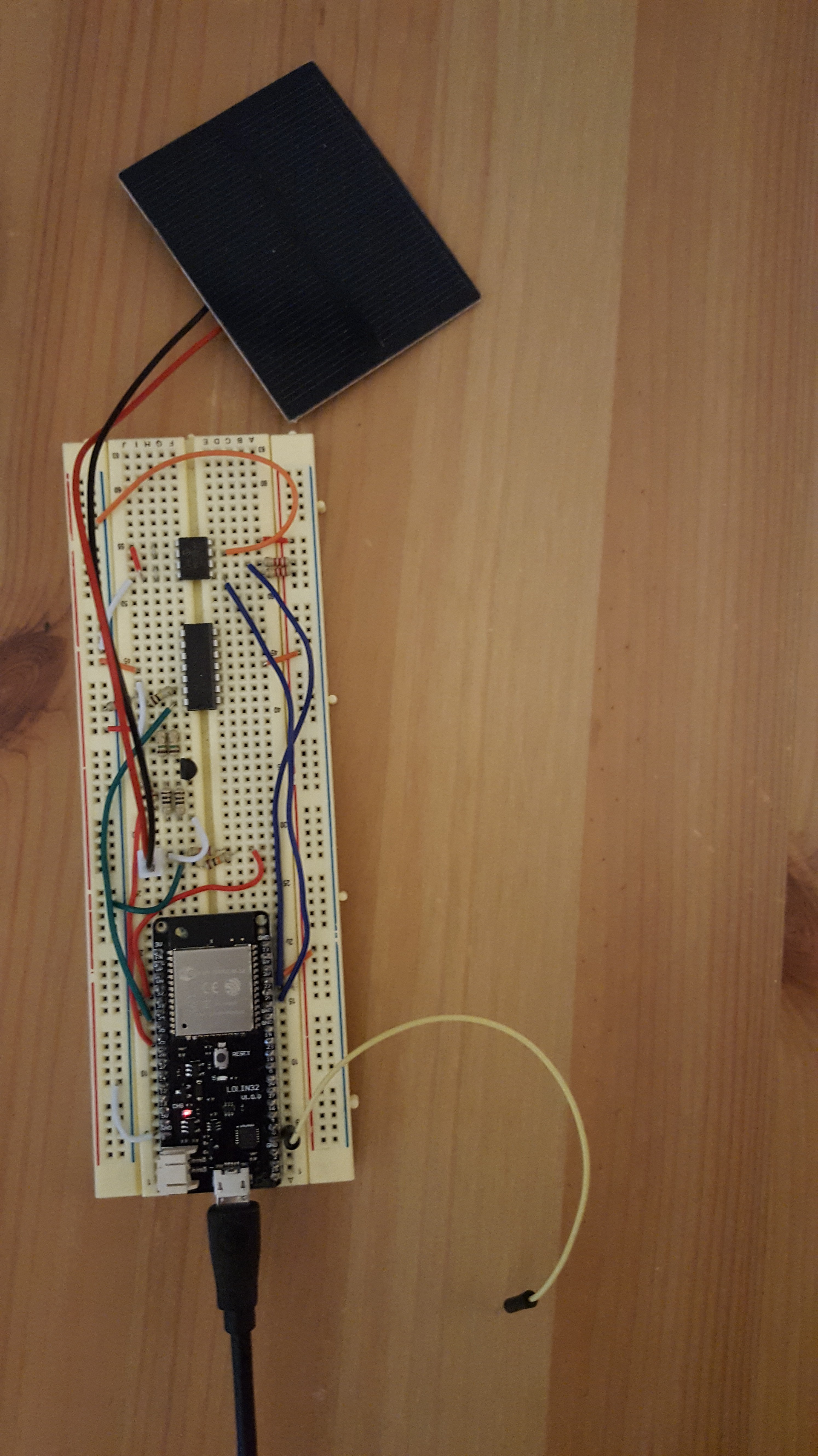
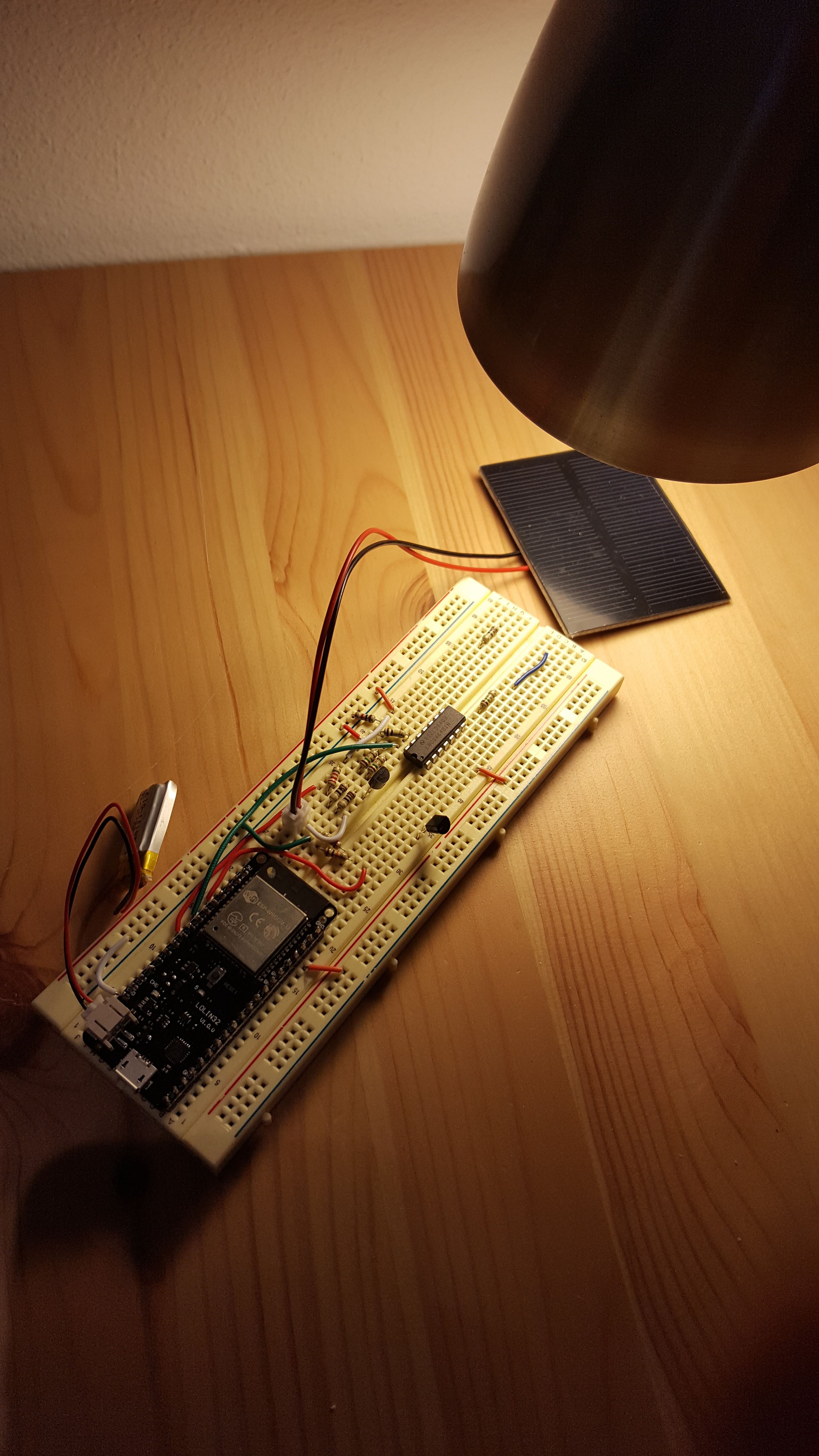
I made a quick prototype with this setup, designed to send data every 10 minutes via WiFi through IFTTT to Google Sheets. The measured maximum power, maximum current, and maximum voltage were recorded. Testing was done with a desk lamp, at a variety of distances from the bulb to the solar panel.
![]()
The above image shows the prototype on a breadboard. The ESP32 module is running off of a 110mAh lithium polymer battery.
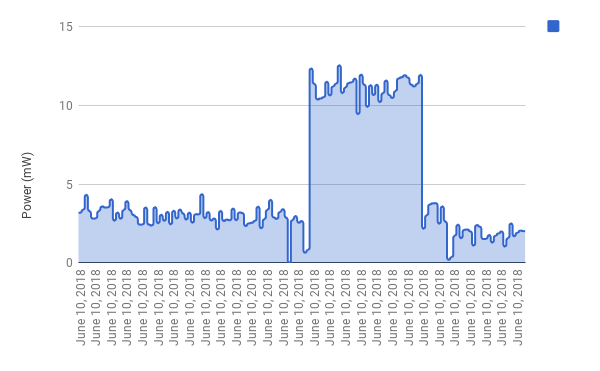
![]()
The above plot shows recorded power data for a few hours. This plot has three clear sections, corresponding to three physical setups in the relation between the lamp and the solar panel.
More to come...
SOL: Long-term solar intensity sensing
SOL is a project to develop a solar powered, connected solar intensity sensor (also known as a pyranometer)